Schlagwort: raspberrypi

  • Novaspirit Tech, aka Don Hui interview

    Novaspirit Tech, aka Don Hui interview

    Reading Time: 3 minutes

    Novaspirit Tech started back in 2003 as a placeholder for my Macromedia Flash web designs on GeoCities,” he recalls. “Then I relaunched the website at its own domain in 2010 to host my tutorials and projects, such as installing GPU on laptops to installing kernels on Android phones.

    In 2013 my website crashed and lost the data, so I looked towards YouTube to host my tutorials, and at the same time I discovered Raspberry Pi. That’s when it started to really define the tech in Novaspirit, putting together hundreds of projects for myself, friends and families.”

    What is your history with making?

     Water-cooling a Raspberry Pi is unnecessary, but very fun to see

    I’ve been a tinkerer since I was a kid. I would love to take things apart and try to rebuild or improve on them. That’s where my quote ‘Hack till it hertz’ originated from, which means hack it till it works. Making devices do what they were not first intended to do was my specialty and also my flaw, because I tend to break more things than I fix.

    How has Raspberry Pi helped some of your builds?

    Donald used to do a lot of hacks like this, installing GPUs into laptops

    Raspberry Pi has been a very critical part of my creations because I use it for what it’s intended for, a dev board. Most of my projects will start with a Raspberry Pi, whether building a small web server or running a garage door opener with GPIO. Every step of the way you will always need an environment that is reliable and doesn’t change too dramatically. From building the base code to GUI and interacting with GPIO, it’s always nice to start with a board like Raspberry Pi.

    What has the response been to your videos?

    Hacky makes with Raspberry Pi is Donald’s specialty

    Most of the projects I’ve done with Raspberry Pi have gotten a lot of good feedback, mostly impressed at how I managed to get things to work on Raspberry Pi. I believe I was the first to install Amazon Echo on Raspberry Pi, as well as Windows 10 on ARM on Raspberry Pi. I’ve even water-cooled a Raspberry Pi. I do have many firsts and the responses I get are great, although the water cooling one was just for jokes.

    What are some of your favourite Raspberry Pi builds?

    My favourite Raspberry Pi builds are the ones I use every day. The quad SATA Raspberry Pi NAS, USB over network with Raspberry Pi, and my most recent Raspberry Pi kvm-over-ip.

  • Raspberry Pi 400 Projects & Guides in The MagPi Magazine #101

    Raspberry Pi 400 Projects & Guides in The MagPi Magazine #101

    Reading Time: 3 minutes

    Raspberry Pi 400 Projects & Guides

    But where to start? That’s where our lead feature comes in. It’s packed with information and advice for getting the most out of your new Raspberry Pi 400 computer.

    Arts & Crafts with Raspberry Pi

    Get creative with Raspberry Pi arts & crafts projects

    Get out your sticky tape, cardboard and crafting tools with our guide to making things with an electronic angle. Discover a wide range of crafting projects that use lights, sensors, and buttons. We’ve got fashionable wearables, interactive art displays, plus badges and baubles. Everything you need to get inspired by making with Raspberry Pi. 

    Use a retro DB9 joystick with Raspberry Pi 400

    Wire up a retro joystick to Raspberry Pi 400

    We love the classic DB9 joysticks, made popular in the 1980s (like the Kempston one we use in this tutorial). Nothing beats playing retro games with an original joystick. In this tutorial you’ll learn how to use a DB9 adaptor and wire it up to the GPIO pins on a Raspberry Pi 400 computer. Then plug in your original joystick and play games in the original way.

    BOSEBerry Pi

    Upcycling an old speaker system with ultra-modern innards

    We love this BOSEBerry Pi project by David Hunt. He has taken an old BOSE SoundDock from the iPod days and upcycled it with Raspberry Pi. Now it can stream music, internet radio, and keep him updated with the latest news and events. 

    Santa's Run: Drop & Dash

    Upgrade Santa’s Run with Drop and Dash games

    Santa’s Run is a great game that uses recycled plastic bottles and arcade buttons as controllers. This month, Mike Cook explains how to use those controllers to make two more games: Santa’s Drop and Santa’s Dash.

    FHD Touch Display and Bluetooth Keyboard

    pi-top FHD Touch Screen and Bluetooth Keyboard

    Fancy turning Raspberry Pi into a Microsoft Surface-style tablet computer? With pi-top’s latest hardware you can add a touch-screen and keyboard cover to Raspberry Pi. The result is the nicest way to work on the move around.

    Pick up your copy of The MagPi magazine #101

    The MagPi magazine is available as a free digital download, or you can purchase a print edition from our Raspberry Pi Press store.

  • Win a Raspberry Pi 400!

    Win a Raspberry Pi 400!

    Reading Time: < 1 minute

    Subscribe

  • Santa’s Run

    Santa’s Run

    Reading Time: 6 minutes

    Step 01: The game

    It’s Christmas Eve, ten to midnight in 2020. The moon is waxing gibbous, at a phase of
    73%, the constellation of Orion stands as high in the sky as it gets from these latitudes,
    and Santa is about to make his overhead pass. He is propelled through the sky by a
    mixture of magic and the energetic shaking of his eager recipients – that’s you. His mission is to deliver every single copy of The MagPi magazine to the people waiting
    below. He has two passes to the end of the screen and back. Will he make it, or will
    some fall into the soggy snow?

    Step 02: The controller

    Figure 1: Photograph of Raspberry Pi computer connection

    The hardware controller we are about to build is about as simple as it gets. It consists of
    a tilt switch mounted in a plastic drinks bottle. This then connects to a GPIO pin on
    Raspberry Pi, and the rest is software. We first used tilt switches in The MagPi issue 52 with the sliders game – coincidentally also a Christmas game, and one of
    our favourites. But this time we only need one switch. We used a small (140mm) flip-top
    drinks bottle from a discount supermarket, and mounted the switch in the top.

    Step 03: Make your shaker

    We used thin screened microphone wire for the connection; it is only 1.6mm in
    diameter. This makes for a nice neat job, but any sort of wire will work. First we drilled a
    2mm hole in the flip top cover, and then threaded the wire through. Then we trimmed
    the wire on the tilt switch down to about 5mm and soldered a wire on each connector
    (Figure 1). Then we pushed the tilt switch through into the bottle until the wires were
    below the level of the rim, and flooded the top recess with hot-melt glue, ensuring the tilt
    switch was vertical, as shown in Figure 2.

    Step 04: Connecting to the GPIO pins

    Figure 2: Hot-melt glue fixing the tilt switch

    To connect the other end of the tilt switch to the GPIO pins, we used a ten-pin dual-row
    header socket. We connected the wires to pins 2 and 9 of the header socket; this
    corresponds to ground and GPIO 3, as shown in the photograph in Figure 3. We used an I2S pin because of the, already fitted, 1K8 (1.8kΩ) pull-up resistor to give it good immunity from interference. Figure 4 shows the physical layout diagram for the whole
    interface. We then ran a short test program, available on our GitHub page, to check it worked.

    Step 05: Graphics

    One of the major components of this sort of project is the graphics, so we got them
    together before starting on writing any code. We looked around the net for royalty-free
    Christmas animated GIFs of Santa’s sleigh, and found a good one with seven reindeer.
    This was too many for our needs, so we used a photo editing package to remove all but
    the first pair. We split the GIF into its separate frames and started editing: first removing
    excess reindeers, then making the background transparent, and finally adding the
    Raspberry Pi logo onto the sides of the sleigh.

    Step 06: Your first dashboard

    Figure 3: Photograph of Raspberry Pi computer connection

    Then we found a chimney and made it a double chimney with a copy and flip of the
    original clip art. We also did some retouching on the snow line between the chimneys,
    to make the transition smooth. Most importantly, we made the snow line at either side of
    the chimneys end at the same height. Finally, we made two lengths of just plane snow:
    one the same length as the chimneys, and the other half the length. In this way, we
    could mix and match the graphic elements in the scrolling ground display.

    Step 07: The MagPi covers

    This could have been hard work, going through all the back issues online and taking
    screen grabs, but fortunately the magazine was planning to put all the covers on the
    front page of the 100th issue, so they had gathered them together already. We only had
    to scale them, in our case to 50 pixels wide. The final element was the star-studded
    background for Santa to ride across, but been very keen on astronomy, we wanted this
    to be accurate, along with the position and phase of the moon. So we turned to a great
    open-source planetarium package Stellarium.

    Step 08: Stellarium

    Figure 4: Physical diagram of the who project

    Stellarium has been around for at least 15 years and is, by now, a very sophisticated
    product available free for all three major platforms. We used it to look at the sky as it
    would be on Christmas Eve 2020. While leap years keep the stars in the same place at
    a specific date from year to year, the moon’s position and phase will change. This year
    the moon is waxing gibbous, at a phase of 73%. ‘Waxing’ means it is getting fuller day
    by day, ‘gibbous’ means it’s between half and full, and &quot;phase&quot; is how much of the moon you can see.

    Step 09: Poetic licence

    We took a bit of poetic licence when it came to the size of the moon. When looking at it
    in the sky, we actually perceive it to be bigger than it really is, so we enlarged the moon
    to match our perceptions. Figure 5 shows the negative of the background image we
    used. It also includes constellation lines and star names – note the position of Rigel in
    the constellation of Orion, as it is a key point in the game. Stellarium is much more than
    a simple planetarium and can animate all sorts of events like the analemma of the sun.

    Step 10: Software

    Figure 5: The night sky used showing constellations and names

    All the software and graphics files can be found on our GitHub page. You use the
    shaker to propel Santa across the sky, and need to keep shaking to keep him going.
    When you have positioned him correctly, you press the SPACE bar to release a copy of
    The MagPi magazine, which then drops to the ground. The longer it descends, the
    faster it drops, as the speed increases because of the acceleration due to gravity. The
    forward speed of the drop, however, is constant. This adds a bit of realism to what is a
    big suspension of disbelief.

    Step 11: The drop

    While the magazine is dropping, Santa’s forward speed is transferred to vertical speed,
    allowing you to control his altitude. This is important, because aiming from low height is
    easer, but you can only drop magazines if the runners on the sleigh are above Rigel. If
    you attempt a drop and you are at the level of Rigel, you will be whooshed to the top of
    the screen. If the magazine’s bottom-left or bottom-right corner intersects the hidden
    capture rectangle on each chimney, it sticks there and is considered delivered; if not,
    then it sinks into the snow and is lost.

    Step 12: Winning the game

    Figure 6: Santa in action, delivering one more magazine

    Santa makes two runs across the screen: right to left, then left to right. The objective is
    to deliver all 100 issues of The MagPi magazine. The game stops when either you
    complete the two runs or you run out of magazines. You get to see the total delivered at
    the end, along with a round of applause. Figure 6 shows Santa on his return run
    adding another magazine to those already delivered.

    Next month, in part two, we will look at using two shakers. So get another tilt switch
    while you are at it, to make more shaking fun.

  • LED Cube

    LED Cube

    Reading Time: 3 minutes

    Sebastian spent some time working on the design and aesthetic of the cube, although ‘technically’ it’s not a cube, as he explains. “Since the cube is designed to be stationary and usually only viewed from one side, it is not actually a complete LED cube, but only has three sides with LED matrix panels. Those panels consist of 64×64 RGB LEDs across a side length of 128mm. They are held by a 3D-printed frame, which also holds a Raspberry Pi 2 and an LED Matrix Bonnet from Adafruit.”

    Glorious graphics

    Sebastian arranged the three panels so that they are daisy-chained to the Matrix Bonnet, which also distributes the 50W from the power supply (5V, 10A). This was the more straightforward element of the whole design, as he tells us. “One could say that I mostly put together a few parts that were meant to be assembled just like this. The trickier part was software, because I did not just want simple pixel graphics or a pre-rendered animation. Even at only 3×64×64 pixels, it soon became clear that the CPU cannot deal with all the pixels in sequence, but that I had to use OpenGL.”

    The workings within the three-sided cube

    The glowing visual element of the Cube is stunning, with the background colour determined by his PC’s Ryzen 5 CPU temperature, and the thickness of the ring changing in relation to usage of threads on the CPU. Sebastian achieved these graphics by using OpenGL Shader: “Instead of iterating over each pixel, one writes a fragment shader – a small (and rather limited) piece of code that is executed independently for every single pixel. With this independent execution, every pixel can be done in parallel as much as the hardware supports this. I did not end up with a particle system, but this allows for an animation that covers all pixels and with something going on in every part of the image.”

    Power management

    Sebastian had very little fine-tuning to do, once he’d figured out how to use OpenGL. “I had to be careful about the maximum brightness because the power supply is a bit too weak to handle full white for all LEDs. So, I had to avoid getting too close to a white cube as the Raspberry Pi would become unstable at this point,” he reveals.

    The Cube in action on Sebastian's desk - an impressive setup

    He also made the Raspberry Pi file system read-only in order to avoid the possibility of data corruption when unplugging the cube. “This way, I could just cut the power at any time without worrying about file corruption. The cube is now simply plugged into a socket strip which turns off whenever the PC does not draw any power on a controlling socket.”

    Sebastian’s colourful creation has garnered much interest from others, which surprised him initially as he was aware that such a cube was not a new concept. “I got extremely positive reactions and a much wider coverage than I expected,” he says. “I think that my presentation in the video was good and that there is a slightly different appeal to it as it has some kind of function, while having very fascinating visuals.”

  • World’s Smallest iMac

    World’s Smallest iMac

    Reading Time: 3 minutes

    The brains behind it is Michael Pick, whose attention to detail is mightily impressive. “I got
    the idea after making my first mini computer, the World’s Smallest Gaming PC, and I thought the Apple iMac would make for a fun and interesting build video,” he tells us. Before cracking on with the task, though, he spent much time preparing.

    “Like all of my builds, I started by modelling all of the components in a 3D CAD program and this allowed me to see and deal with any potential problems before I even started,” he
    explains. “The wiring for this build was rather simple, but if I’m working on something more
    complex, a wiring diagram would also come in handy.”

    Making the cut

    In order to create the smallest possible homage to the iMac, Michael decided to use a
    Raspberry Pi 4 computer from the beginning. But he was mindful that the resulting machine still needed to be useable, so he opted for a 7-inch screen.

    Michael cut the double-stacked USB ports in half and sliced the RJ Ethernet connector using a rotary tool

    “I knew there were lots of 7-inch displays readily available for Raspberry Pi and I didn’t want to go smaller because that would have made it pretty hard to use,” he says. The desire for a slim build, however, meant making some amends to his Raspberry Pi 4 to reduce some of its height.

    “For this, I needed to break out the rotary tool and the first major modification to Raspberry
    Pi involved cutting away the top two USB ports, quickly followed by the removal of the
    Ethernet port,” Michael explains, carefully marking where the cuts would go before getting
    stuck in. “I didn’t need these ports, and eliminating them made the final build significantly
    slimmer. But I had to be careful that I didn’t accidentally cut something I wasn’t supposed to.”

    Another bite

    Once Raspberry Pi 4 had been modified, Michael was able to begin the final assembly, painting the 3D-printed parts and using a low-profile ribbon cable to connect the screen to
    Raspberry Pi while installing iRaspbian as the operating system.

    Connections for a USB power cable and a USB data cable have been created on the underside of the display

    “For entertainment purposes, I think iRaspbian suits this project perfectly,” he says. “I got
    very lucky with the release of iRaspbian because it made this project incredibly easy once I
    got the hardware sorted out.”

    As part of the build, Michael even made a small Apple logo to fit on the front of the case and he stuck to the original colours of black and metal grey. The only part that doesn’t quite fit the aesthetic is the keyboard.

    “Apple’s keyboard is clean and slim and there’s nothing that comes close to matching this
    with current off-the-shelf mini keyboards,” he notes. “I could potentially make a keyboard
    from scratch, but I didn’t have the time. Maybe in the future, this is something I can work on.”

    For now, Michael is planning some more mini-computer builds but he also has plans to take
    on much larger and complex builds. He’s also been able to get some downtime. “I christened my small iMac with a quick game of Minecraft,” he says.

  • Argon ONE M.2 review

    Argon ONE M.2 review

    Reading Time: 3 minutes

    The marquee addition here is support for an M.2 SATA SSD drive (the blade drives
    commonly found in laptops). This sits snugly in a bottom compartment and is
    connected to Raspberry Pi using the USB 3.0 connection (via a U-shaped adapter). It features UASP (USB Attached SCSI Protocol) support to increase performance.
    In the spirit on things, we tested it with a Raspberry Pi 4 8GB RAM and Raspberry Pi
    OS (64-bit) still in beta testing. An internal board repositions the ports to the rear, and converts the micro HDMI
    ports of Raspberry Pi 4 to two full-sized HDMI sockets. GPIO remains accessible via
    a removable flap with a pin guide printed to the side. The aluminium alloy lid acts as a heatsink and a 30mm fan provides active cooling.
    The fan is controlled via a script provided by Argon 40. Default settings start at 10%
    power when the CPU temperature is at 55ºC, increasing to 55% at 60ºC and 100%
    at 65ºC.

    Putting it together

    Your M.2 SATA SSD clips into the lower part of the case and is held in place with a
    single screw. The two halves are then screwed together and a U-shaped USB
    adapter is used to bridge the lower part of the case the port on the upper part.
    It’s an ingenious solution, but you lose a USB 3.0 socket in the final build. More
    importantly, the microSD card socket is sealed inside the case, requiring
    disassembly to access it.

    The two halves of the case connect together with a U-shaped USB 3.0 connector bridging the M.2 SSD SATA drive to Raspberry Pi 4

    Raspberry Pi EEPROM recently provided USB boot support in the default ‘critical’
    firmware, and a recent update (still currently in beta but due soon) improves USB
    boot performance. Once booted into Raspberry Pi OS, we installed Imager and used that to flash a
    clean install of Raspberry Pi OS (64-bit) onto the SSD drive. Remove the USB thumb
    drive and Raspberry Pi boots straight from the SSD.

    Benchmarking the Argon M.2

    We used a Samsung 850 EVO supplied by our friends at Custom PC magazine and installed Gnome Disks for its benchmarking test. The M.2 did not disappoint, with an average read rate of 367.1MB/s compared to
    45MB/s for our SD card. That’s an 800% speed increase. Overjoyed with our SSD throughput rate, we set about testing CPU speed and
    thermal performance (the two are related as Raspberry Pi OS throttles performance
    if the CPU temperature exceeds 80°C). We performed a similar test to the one Gareth Halfacree uses when thermal testing
    Raspberry Pi boards
    . We ran stress-ng and glxgears for ten minutes while monitoring CPU speed and temperature recordings, followed by a
    five-minute cool-down period. The Raspberry Pi under stress remained cool, maxing out at 53ºC – not even high
    enough for the fan to kick in, with the passive case doing all the cooling. We took our
    Raspberry Pi clock speed up to 1800MHz and, after leaving
    Raspberry Pi to recover, ran the test again. This time the board got a little more
    stressed, maxing out at 73ºC – enough for the Argon fan to kick in at 100% speed,
    but below the critical 80ºC point where Raspberry Pi OS begins to throttle back the
    CPU speed. So at all times you get unrestrained performance with an overclocked Raspberry Pi 4
    coupled with an ultra-fast SSD storage solution. If that’s not nifty, we don’t know what
    is.

    We did also install Ubuntu, but we could not install the scripts for the fan in this case
    (as it depends on GPIO Zero), so the fan was on permanently. Raspberry Pi OS remains our preferred operating system at any rate. We spent a delightful couple of days knocking together the scripts for testing in
    Visual Studio Code and creating graphs of the results in LibreOffice, all while doing browser research and writing up the results. Our Argon ONE M.2 build remained a
    joy to use throughout.

    Verdict

    10/10

    If you want to take Raspberry Pi 4 performance as far as it can go, this is the way to
    do it.

  • Build a Home Assistant: the light fantastic

    Build a Home Assistant: the light fantastic

    Reading Time: 6 minutes

    We’re going to use the Ikea Trådfri range in this tutorial, but you can also use other compatible ranges such as Philips Hue. So, let’s brighten up our day (and night) without the need for boring light switches.

    Step 01: Install your smart light system

    Like many ‘smart’ light systems, Trådfri uses direct radio communication using a protocol
    called ZigBee. To control the lights from a computer, the easiest approach is to add a
    suitable gateway. These are normally inexpensive and are often cross-compatible (as with
    Trådfri and Hue). Once installed, the Ikea Trådfri Gateway will allow not only your
    smartphone to control lights but also Home Assistant. Typically they need a wired
    connection, so it’s a good idea to have your Home Assistant Raspberry Pi computer wired
    on the same network switch for reliability. Follow the supplied instructions and get set up
    before moving on.

    Step 02: Pair up your lights

    It’s far easier to get your new smart light setup running as a closed system first: it makes
    discovery easier later on. We’re going to cover a number of different scenarios such as an
    automated porch light and a group of lights that can act as one. These will all need setting
    up in the Trådfri smartphone app so they are recognised by the gateway. You can also
    group them if you want to, as that will be helpful later and save some work. Don’t feel you
    have to follow our setup here – you can use a single light or as many as your home can
    take.

    Step 03: Integrate!

    There are a wide range of cards for setting up controls, and you can design your own

    Once you’re happy your smart light gateway is running, log in to Home Assistant and go to
    Configuration, Server Controls, and then click ‘Restart’ under Server Management. This
    will cause Home Assistant to rescan the network for new devices. Luckily, Home Assistant
    is capable of spotting a Trådfri gateway automatically and you should get a notification that
    a new integration has been discovered. You can now enable the integration and Home
    Assistant will automatically add all your lovely new lights. Each light will be added as a
    device, something on your systems and an entity – a single thing that can be controlled.

    Step 04: Nice name

    Now Home Assistant is aware of your fancy new lights, it’s time to make things a bit more
    friendly. Each light now has an entity code in the system. These are normally in the form of
    type-dot-name, so as the device type is ‘light’, you’ll see entities such as
    ‘light.tradfri_bulb_1’ listed under Configuration – Entities. You can click on these to give
    them more meaningful names and place them in ‘areas’ such as the kitchen or lounge.
    Once you’re happy with all the names and places, you can add cards to the main control
    panel.

    Step 05: Card-making

    Last month, we configured the default dashboard ‘Overview’ and switched off automatic
    updates. If you did this, then (surprise!) controls for your new bulbs will already be
    available. Otherwise, click the three dots in the top-right-hand corner and then ‘Configure
    UI’. Now click the bottom right ‘+’ to add a new card. Choose the ‘Light’ card. Chances are,
    Home Assistant will have picked up your bulb and name. If not, click the arrow to select
    the entity you need. Click ‘Save’ to add your new card. You should now be able to tap the
    card to control your light and the slider to set brightness (if your light supports it).

    Step 06: Add in an add-in

    For one of our setups we want many lights to be controllable together, including dimming.
    This is a bit trickier and not something we can do in the interface – we’ll have to edit a
    configuration file. To do that, we need to get console access and that means installing an
    add-in. Add-ins extend Home Assistant’s core functionality. Click on ‘Supervisor’, then
    ‘Add-on Store’ to see what’s available. Search for ‘terminal’ and install the ‘Terminal &amp;
    SSH’ add-on. Once installed, ‘Terminal’ will appear on your sidebar. Click it to get a
    command line prompt. Also you now have SSH access to your installation if you want.

    Step 07: Configure it out

    The add-on store extends your server in all kinds of ways

    To control our multiple lights with one control, we need to create a single ‘virtual’ light. This gives us the chance to familiarise ourselves with Home Assistant’s configuration files. Click
    on the Terminal add-on and then enter

    cd config

    . In this directory are all the configuration files for the system. To make our virtual light we need to edit configuration.yaml. YAML files are text files that use indentation and special characters to convey meaning. The main file is configuration.yaml. Any changes made there require Home Assistant to be restarted. Others, such as groups, can be dynamically reloaded from Configuration – Server Controls.

    Step 08: A little light typing

    The virtual light group is a little special, so it has to be created in the main
    configuration.yaml. Edit the configuration file as follows:

    nano ~/config/configuration.yaml

    Now enter in the example shown at the end of the file. You’ll need to change the entities to
    match your installation and of course you can change the name to anything you wish. If
    you add any further groups, you should add them under the existing ‘light’ section. Save
    the file with CTRL+X and then restart Home Assistant to pick up the changes. You should
    now be able to add a new card to the dashboard which will use your new bulb and control
    everything in sync.

    light: - platform: group name: Kitchen Lights entities: - light.tradfri_bulb_1 - light.tradfri_bulb_2

    Step 09: All in good time

    Let’s create an automation to switch the kitchen lights off at 11pm. Click ‘Configuration’
    then ‘Automations’. This is the most powerful area of Home Assistant and we’ll go more in-
    depth next month. For now, click the ‘+’ icon and, when prompted, enter ‘turn off the
    kitchen lights’, then ‘create automation’. This will set up a basic automation for you. Go to
    ‘Triggers’, select a type of ‘Time’, and enter ‘23:00’. Make sure all your lights are selected
    under ‘Actions’ and then click the save icon (yes, it’s a floppy disk). Now your kitchen lights
    will switch themselves off every night at 11pm. Can you get them to switch on?

    Step 10: Triggered

    A key part of automations is the ‘trigger’: the event or change that causes an automation to
    run. Triggers are fed by sensors, devices connected to the system that feed it information,
    rather than being something it controls. Examples are temperature, humidity, movement
    (PIR sensors), and buttons. Home Assistant automatically adds the sun (!) as an input and
    knows when the sun rises and sets, so automations can be triggered. If you have a porch
    light, this is a simple step and the language parser will accept ‘switch the porch light on
    when the sun sets’ and configure everything for you. Remember to ask it to switch it off
    again!

    Step 11: Setting the scene

    Another way of controlling groups is to use ‘Scenes’. You’ll find the scenes editor under
    Configuration. A ‘scene’ is a group of devices that you would want to group together in a
    particular way. For example, you might want a single button that turned off the main light,
    turned on the mood lights and started playing music on your smart speaker. This works by
    adding entities together in a scene and then creating a button in the dashboard to trigger
    that scene. You can also have the scene triggered using automations; imagine having the
    lights and music come on when you entered the house by using your smartphone app as a
    trigger.

    Step 12: Notifications

    Now it may not be very useful to know that a light has come on, but it does make for an
    interesting example of how notifications work. Let’s say you wanted an alert when the
    porch light switches on. You firstly need to add a notification provider to configuration.yaml. There’s an example here for one of our favourite services, Pushover.net:

    notify: - name: pushover platform: pushover api_key: <YOUR API KEY GOES HERE> api_key: <YOUR USER KEY GOES HERE>

    Once added (and with the service restarted), you can add notifications as an
    action on any automation. There is support for virtually every popular notification system
    out there.

  • iPourIt

    iPourIt

    Reading Time: 2 minutes

    The substitute beer was lousy too. “It was time to take things into my own hands” said
    Brett, ‘I could have got my own beer in that time’. Brett set about creating a self-service beer dispenser in which customers chose and paid for their drinks at their table and then went and helped themselves to it. ID checks and a tab were organised at the counter, a touchscreen terminal is used to select the size and volume, and an RFID wristband used to link the drink dispensed to the customer’s account.

    Let the good times flow

    The tablet computers iPourit originally used, however, proved a weak link, since their
    screens needed to be constantly active, which was costly, and they eventually stopped
    working.

    Each Raspberry Pi 4 controls twelve beer lines, so customers get plenty of choice

    Over the past year iPourit has developed a new type of self-service beer wall with
    Raspberry Pi at its heart. The iPourit system uses Compute Module 3+ (the industrial
    version of Raspberry Pi 3B+) as part of a power-over-Ethernet beer dispenser. The
    customer gets a highly detailed view of which beers are selling. “Every single controller,
    every single tap stream on this system is powered and communicated by a managed
    switch. We put a valve and a meter in the beer line. The network has one Raspberry Pi 4 for every twelve beer lines which controls and measures them,” enthuses iPourIt CMO Darren Nicholson. The Raspberry Pi setup works with their existing .NET shop setup, which is ideal for any bug fixes and upgrades and meant they didn’t need to start from scratch.

    The customer's drinks tab is set up when they arrive and links to an RFID wristband that activates the dispensers at the beer wall

    The beer wall concept had previously offered a quirky point of difference for venues. With
    contactless service now the aim of most hospitality venues, the idea has struck a different
    kind of chord with bars and restaurants. A specially designed RFID tag – controlled by
    Raspberry Pi, of course – unlocks the pump handle to pour the beer features a hook that
    allows customers to pull the handle without touching it.

  • Amit Rana Interview

    Amit Rana Interview

    Reading Time: 3 minutes

    “This developed my interest in the teaching industry,” he tells us. “After quitting my job
    quite early in my career, the first thing I did was to start a training centre.”

    In the beginning, he was mostly teaching engineering students, training them with practical
    hands on with microcontrollers and Raspberry Pi.

    “Slowly we started conducting training for school students, teaching them how to build
    robots, how to make apps using App Inventor, Python programming, and Arduino,” Amit
    says. “For a couple years we also ran a Code Club, which was an activity where we used
    to visit schools and teach Python and HTML.”

    Amit's training courses cover IoT with Raspberry Pi and microcontrollers

    What kind of things do you teach?

    I mostly teach internet of things, Embedded Systems and PCB Design. I use Raspberry Pi,
    Azure IoT Hub, AWS IoT Core, AVR / ARM7 microcontrollers, PIC microcontrollers, [and]
    Eagle and KiCad for PCB design.

    How did you find out about Raspberry Pi?

    When Raspberry Pi was to be launched, I was getting newsletters from element14 and
    had read a few posts on social media, so I ordered it first thing when it was launched in
    India. I still have my first 256MB board with big SD card slot, and it’s working just fine.

    Originally, Amit trained older students, but he's since trained school children

    What is Kitflix?

    Kitflix is an e-learning website which hosts online courses on electronics, embedded
    systems, IoT, and programming, using recorded self-paced and live online sessions.

    How has Kitflix been received?

    As said, I also had a training institute (Vidya Robotics) which is closed now. Kitflix is a
    brand we chose for our online course platform which sounds a little catchy. So far we’re
    doing good: we have more than 17,200 students across 150 countries for our online
    courses through Kitflix and other partner sites like Skillshare and Udemy. And we have
    about 1000 visitors each day to our website.

    Amit also used to run a Code Club

    Any student success stories you can share?

    There are many. Some of them are listed on our homepage. Many of my
    students are now working in a variety of industries across the globe. Many went on for
    higher education in countries abroad; many are working for elite institutes like IIT in India.

    Anything else you’d like to add?

    I am a person passionate towards spreading the education in electronics, embedded
    systems, and IoT, which is a field often considered [to be] under the umbrella of IT skills,
    but still it’s excessively big and all-encompassing. My vision is to create a kind of ‘Khan
    Academy’ for electronics and programming education.

  • Build a handheld console

    Build a handheld console

    Reading Time: 6 minutes

    The PiBoy DMG is more expensive, chunkier, and much more powerful. It has a 3.5-inch
    640×480 display, both digital and analogue controls, and a total of ten buttons. You can
    access all Raspberry Pi 4’s USB ports and there’s an optional mini HDMI pass-through. It
    won’t run off AAs, so the full kit ships with a 4500mAh rechargeable battery.

    Step 01: Install RetroPie

    Use Raspberry Pi Imager for Windows, Linux and macOS to download and write
    RetroPie (RPI 1/ZERO) on a microSD card. 8GB capacity should be fine for our purposes,
    as none of the systems we’ll be emulating involve large files. Before you install Raspberry Pi Zero in the GPi Case, you connect it to a monitor, a
    keyboard, and the internet to install RetroFlag’s safe shutdown script. Insert your microSD
    card and connect your peripherals. Allow RetroPie to boot, then press F4 to quit to the
    command prompt.

    Step 02: Basic config & safe shutdown

    Type

    sudo raspi-config

    . Now go to Network Options. Go to Wi-Fi and set your country,
    network name (SSID), and password. In Localization options, Change Keyboard to make
    sure your keyboard is properly configured. TAB to Finish on the main menu, press ENTER
    and reboot. At the command prompt, type ifconfig to confirm that your wireless network is
    connected
    Finally, on a single line, type:

    wget -O - &quot;https://raw.githubusercontent.com/RetroFlag/retroflag-
    picase/master/install_gpi.sh&quot; | sudo bash

    This will download and run the safe shutdown installer before restarting Raspberry Pi Zero.
    Power down and unplug the system.

    Step 03: Add display support

    Return the microSD card to the system you’re using to prepare the OS for use. Download
    this patch zip file and unzip it. The readme file includes instructions for Windows and macOS – the latter also applies to
    Linux operating systems including Raspberry Pi OS. From the boot partition of your RetroPie disk, copy config.txt to the original_files
    directory in the patch’s folder and replace it with the one that you’ll find in the patch_files
    subdirectory. Similarly, back up dpi24.dtbo from RetroPie’s /boot/overlays folder to the supplied
    overlays directory, then copy over dpi24.dtbo and pwm-audio-pi-zero.dtbo from the
    patch_files subdirectory to RetroPie’s overlays folder.

    Step 04: Prepare the case

    The RetroFlag GPi Case comes with a helpful illustrated installation guide, a USB power
    cable, plus the screwdriver and four screws you’ll need to assemble your handheld.
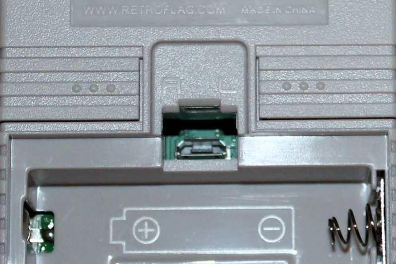
    Open the battery compartment at the back and flip the Safe Shutdown switch to the ‘on’
    position. Make sure the main console power switch is in the off position. Remove the ‘cartridge’ – actually a Raspberry Pi Zero case – from the slot at the top of the
    console; turn it so that the sticker’s facing you and gently but firmly pull it apart.
    Remove the microSD card from Raspberry Pi and the microSD cover from the case.

    Step 05: Install Raspberry Pi

    Place Raspberry Pi loosely into position on the four mounting posts in the shell, with the
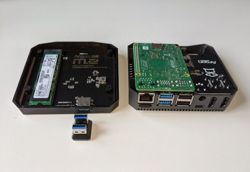
    SD slot facing the gap you removed the cover from. Connect the micro USB extension ribbon cable from the I/O conversion board that comes
    installed in shell 2 to Raspberry Pi’s USB port (the rightmost – the other one is only for
    power). Now seat Raspberry Pi into shell 1 and position the I/O board on top of it. Make
    sure both the posts and GPIO pogo pins are lined up. Reinsert the microSD cover, clip the cartridge halves back together, and install the
    supplied screws into the holes on the back to secure it. Open the SD card cover, insert
    your card, close it, and slide the cartridge back into the main body of the case. Insert three
    AA batteries.

    A micro USB port under the GPi's battery cover can provide USB peripheral connectivity via a powered hub

    Step 06: Power up and configure

    Flip the power switch at the top right and RetroPie will boot. The GPi Case registers as an
    Xbox 360 pad, less a few buttons, though left and right buttons are hidden on the back of
    the case. Hold any button to start configuration. When you get to a button that doesn’t exist, press
    and hold any button. Skip hotkey configuration and allow RetroPie to auto-configure it as
    Select when prompted. You’ll be able to exit to the menu from games by pressing Start
    and Select at the same time. In the front end, tap A to enter the RetroPie menu, scroll to RetroPie Setup, and tap A. Go
    to Configuration / tools, select Samba, and Install RetroPie Samba share to create a
    network share so you can easily copy game files over to the console’s ~/RetroPie/roms
    directory. RetroPie Setup also allows you to install new emulators.

    Step 01: Image your microSD card

    Experimental Pi has its own fork of RetroPie, tweaked to fully support the handheld’s
    features. Download and extract the PiBoy DMG Official Image operating system image and flash it to your microSD card using the Raspberry Pi Imager tool. Alternatively, you can install RetroPie – or any other Raspberry Pi OS/Raspbian-based
    operating system – but will have to add Experimental Pi’s safe shutdown and on-screen
    display scripts, available here.

    The cartridge that slots into the GPi Case is really a swappable Raspberry Pi Zero case, so you could keep different game collections on separate systems

    Step 02: Chassis preparation

    Experimental Pi’s illustrated online assembly instructions for the PiBoy DMG are among
    the best we’ve seen, so keep them on hand during this build. The PiBoy DMG Full Kit comes with the battery, screws, screwdriver, buttons, and blanking
    plates that you’ll need to build it. It’s worth adding the HDMI adapter to your order, too. Unscrew the back of the case, and then unscrew and lift off the fan assembly that’ll keep
    Raspberry Pi cool in situ.

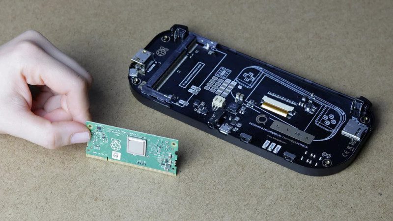
    Step 03: Install Raspberry Pi

    Slip the supplied faceplate over Raspberry Pi’s ports – and, if you’re using it, fit the PiBoy
    HDMI adapter to the rightmost micro-HDMI port and slide its faceplate on. Gently push the SD card adapter ribbon cable into Raspberry Pi’s microSD slot, then lower
    the computer and HDMI adapter onto the standoffs. Screw the HDMI adapter into position.
    If you’re not going to use this adapter, fit a blanking plate in its place.

    Step 04: Fit the fan

    Add the fan board: making sure that it’s lined up with the GPIO, gently seat it into place – a
    rocking motion works well for this. Make sure all cables are correctly lined up and screw
    the board down. Line up and gently press into the place the IPS screen cable. Place the supplied power switch onto the switch on the top right of the board and screw
    the rear of the case back on. Fit the rechargeable battery – it’ll only connect one way
    round, but there are also polarity markings to help.

    The PiBoy DMG case has a built-in fan, which makes it a little noisy but also means you can overclock it to run demanding games

    Step 05: Go wireless

    Slide the microSD card you imaged earlier into position and power up. To add wireless
    networking to our handheld build, mount its microSD hard disk on any other computer. In
    the top-level /boot directory, create a file called wifikeyfile.txt. It should contain the
    following lines:

    ssid=&quot;wifi_name&quot;
    psk=&quot;password&quot;

    Save the file, unmount the card, return it to your handheld, and boot. From the RetroPie
    menu, select ‘Wifi’, then import WiFi credentials from /boot/wifikeyfile.txt.
    As with the RetroFlag build, it’s worth enabling Samba for ease of transferring software to
    the console (see Build 1, Step 6). Transfer your games and you’re ready to play on the
    move.

  • Interactive Storytelling Radio

    Interactive Storytelling Radio

    Reading Time: 3 minutes

    The Interactive Storytelling Radio uses the same idea and asks the listener to decide
    what happens next. The response prompts the built-in Raspberry Pi to jump to the
    appropriate bit of the script and narration to continue. “The aim of the Interactive Storytelling Radio was to recreate the experience of
    choose your own adventure books, but with voice controls,” explain makers Dane
    and Nicole, aka 8 Bits and a Byte. “The radio reads the story to you and when you
    need to make a decision, you simply say it out loud and the story continues.
    Raspberry Pi is the control centre of the project, passing the data back and forth to
    all the separate components, making everything work together.” An extra thrill is that the radio housing the clever storytelling setup is a Telefunken
    Bajazzo TS, a West German model dating back to the 1960s and the Cold War era –
    “hence the story’s spy theme!” say the makers. They found the vintage radio for sale
    in a thrift shop where they live in Brussels, adding to the intrigue.

    Careless talk creates lines

    8 Bits and a Byte is the maker name for husband and wife Dan and Nicole. Having
    learnt to code while they were studying, they soon encountered Raspberry Pi and
    quickly incorporated it into many of their creations. Even though making as a spare
    time endeavour, they’ve posted 47 projects in the space of two years! “A Raspberry
    Pi is a great starting point for any project,” they say, modestly downplaying their
    quirky ideas as “questionable creations”.

    The makers carefully dismantled a vintage radio and reused some of the parts

    The aim of this project was to make “a voice-controllable, interactive, storytelling
    device”. As well as the radio’s case they were able to salvage the original speaker
    and on/off button and to keep the part holding up all the buttons. They still needed a
    microphone, but most of the rest of the setup was accounted for with a Raspberry Pi
    3B+ and Google AIY Voice Kit. Helpfully, both these were items the duo had already
    from previous projects.

    Assembly-wise, they followed Google’s setup instructions, substituting the kit’s speaker and button for those from their vintage radio. Testing involved trying out some of the examples listed on the AIY GitHub page.

    Adventure time

    They now needed to write the storyline – a spy story seemed to be obvious given the
    host radio’s Cold War origins – and a decision tree to plot the flow. Seeing it
    recommended in the AIY Voice Kit guide, they used Google Dialog Flow chatbot
    software. Raspberry Pi runs a Python script which communicates with the AIY HAT,
    speaker, microphone, Dialog Flow, and Google Cloud.

    The project uses the original speaker and a Raspberry Pi 3B+ with AIY Voice HAT

    Unfortunately, Dialog Flow “is not actually made to follow a decision tree!” As a
    result, one of the ‘features’ of the Interactive Storytelling Radio is the ability to jump
    between storylines. “For example, if you’ve chosen the lock pick as the answer to the
    first question, but later in the storyline yell “drink”, it will bring you back to the first
    decision point”, explain 8 Bits and a Byte cheerfully. Perhaps because of its quirks, the Interactive Storytelling Radio has caught the
    imagination of makers online, some of who are building their own to use in teaching
    and to help with special needs. Magnificent stuff!

  • Becca Cam Raspberry Pi SLR camera

    Becca Cam Raspberry Pi SLR camera

    Reading Time: 3 minutes

    Becca describes herself as “mostly just a tech nerd that lives in Brooklyn, NY.” She
    approached her first ever Raspberry Pi project with “absolutely zero background in
    computer science”, but she heard about Raspberry Pi’s High Quality Camera because she
    reports on camera launches for work. When New York City went into lockdown, she was
    tasked with creating camera content without being able to go anywhere and capture the
    world. “That’s when my inner Victor Frankenstein was born,” she says. “What if I built a
    camera instead of reporting on everyone else‘?” She had several film cameras but “no desire to pay to run film through them”. Instead,
    Becca pondered whether she could retrofit one with a digital camera and use it without the
    film developing cost. Handily, Raspberry Pi Foundation had sent her a High Quality
    Camera to review. “Thank y’all so much!” she says, explaining how Becca Cam came to
    contain a Raspberry Pi 4.

    Learning by doing

    Becca began with an old toy camera, C-mount lenses, a Raspberry Pi 4, and a Raspberry
    Pi High Quality Camera module. “The goal was to use the camera hardware as a case and
    as optics, but hide Raspberry Pi and the camera module inside of it”, she says.

    Becca used items she had to hand to keep producing camera-related articles. Happily, she had a Raspberry Pi HQ Camera

    With no programming experience, Becca relied on code she found at the Raspberry Pi Camera Guild and several forums for guidance. “Lack of knowledge was the largest limitation to me. I am a tactile learner with mild dyslexia, so thinking in numbers and letters was not always an enjoyable experience,” she explains. Nonetheless, she persevered, taking her time whenever she had to enter code, and paying close attention to a similar project by Nick Poole from SparkFun. “Originally I thought I could create a digital button to trigger my capture, on a 4-inch
    touchscreen. When that wasn’t working, I remembered that Nick had used a microswitch
    as a trigger and decided to go that route as well,” she says.

    Build better, Bec

    Becca details the process of building her eponymous camera on YouTube. She started with the software, to make sure she could get the camera to take photos. She then put Raspberry Pi 4 into the camera body, before going out and about using it so she could troubleshoot any issues that arose. “Wow, it sounds so straightforward when you type it like that, but there were hiccups at almost every step,” she observes.

    This upcycling project offers the ideal excuse for anyone who's ever wanted to take apart a camera

    If you’re thinking of your own Raspberry Pi project, Becca advises: “The best lesson I
    learned was find someone who knows a bit more than you so when you are falling on your
    face, they can swoop in and save you!” She already plans to take her own advice. New York’s transit authority released an API for
    its trains a while back. “When I am feeling up to another Raspberry Pi project, I would
    really like to make a train time display for my local train that I could put by my door. That
    way I would know the perfect time to leave the house!”

  • ExoMy 3D Printed Mars Rover

    ExoMy 3D Printed Mars Rover

    Reading Time: 3 minutes

    The terrain on Mars is notoriously difficult, so any vehicle intent on exploring the Red
    Planet needs to be pretty hardy. Something small and agile, powered by a dependable yet
    powerful on-board computer, is likely to fare best against such unforgiving terrain.
    Something, perhaps, like a Raspberry Pi. “The rover is inspired by the ExoMars rover Rosalind Franklin and features its most
    characteristic design features (drill, solar panels, wheels),” explain ExoMy’s makers
    Maximilian Ehrhardt and Miro Voellmy from the ESA’s Planetary Robotics Laboratory. “Its
    triple bogie locomotion suspension and six steerable wheels allow for locomotion in very
    rough terrain and [also mean it’s able to traverse] obstacles larger than the size of the
    wheel.” Better yet, ExoMy can be controlled using a gamepad or a web interface where the
    video stream from its on-board Raspberry Pi camera is also displayed. Raspberry Pi 4 Model B is the ExoMy’s main board computer, receiving driving commands
    via the web interface. Raspberry Pi “converts them into motor positions and velocity, which
    are sent via I2C to the PWM motor board to make the rover move,” reveals Miro.

    Small and perfectly formed

    The rover is made from 3D-printed parts and readily available servo motors and screws, plus a Raspberry Pi 4 and Camera Module v2

    Max and Miro chose Raspberry Pi for ExoMy because it “allows the use of a full-fledged
    operating system and provides a wide variety of GPIO pins and a great camera interface.”
    They were also attracted by its low cost, worldwide availability – important given their
    ambition to make space robotics more accessible – and the large community surrounding
    it. “ROS (Robot Operating System) support meant we could use a lot of available open-
    source software and ensure that ExoMy stays very modular,” says Miro. Both engineers had used Raspberry Pi in projects before. Miro used Raspberry Pi to
    control a spherical robot at the Automation and Robotics Laboratory at ESA that floats on
    air and which simulates satellites and spacecraft control algorithms.
    Max, meanwhile, worked on a sounding rocket project at university for which he created a
    Raspberry Pi telemetry logging HAT.

    Building blocks

    Robotic engineers Maximilian Ehrhardt and Miro Voellmy

    Although other open-source rovers exist (notably Sawppy and JPL), these had customised
    metal housings and are far more expensive than the $250 to $500 required to build your
    own ExoMy. A well-received prototype had been produced by trainees in 2018, but it was
    rather costly and had reliability issues. At the start of 2020, Miro and Max set out to design
    a reliable and reproducible version that was also far more affordable. They designed all
    the mechanical parts at the Planetary Robotics Laboratory and 3D-printed them, which
    took approximately two weeks. Assembly required another two days. The electronics and
    screws all came from commercial suppliers. “The idea was that everyone interested in building ExoMy can easily order, install, and use
    it. They can even use the same software tools as in the Planetary Robotics Laboratory,”
    says Max. “We try to use as much open-source software as possible,” adds Miro. “ExoMy
    is, however, designed in SolidWorks, which is unfortunately not free.”
    Details of both the hardware and the freely available software used can be found here.

    ExoMy is intended to be replicable. This US version even impressed its notoriously inscrutable housemate, Mitchell

    Max and Miro encourage others to give it a try and advocate using Docker, since it
    reduces the need to repeat installations and “allows for a repeatable and reliable software
    environment”. Discussing your design challenges with someone, getting a second opinion,
    and inviting different views of a problem generally leads to the best solutions, they advise.
    You can find out more about ExoMy by joining on Discord.

  • The MagPi magazine issue #100 special

    The MagPi magazine issue #100 special

    Reading Time: 3 minutes

    The MagPi magazine issue 100 cover

    The special red-foil cover is in Raspberry Pi colours (red and white) and unfolds to reveal all 100 covers of The MagPi magazine. Inside the special edition is a 20-page feature celebrating 100 moments from Raspberry Pi history.

    100 moments: The MagPi's amazing achievements

    Discover 100 Raspberry Pi moments

    We’ve scoured the previous editions, talked to all the community, and all reminisced over eight years of Raspberry Pi. The results is 100 greatest Raspberry Pi moments, achievements, and events from 100 editions of The MagPi magazine.

    Santa's Run

    Make Santa’s Run with recycled bottles

    Mike Cook serves up a double-whammy for Christmas with a game that has you delivering all 100 editions of The MagPi. Santa’s Run uses recycled plastic bottles as controllers. 

    The ExoMy Mars Rover is just one of many amazing projects in The MagPi #100

    ExoMy Mars Rover and other amazing projects

    We’ve gone all out this month with some of the best community projects ever to feature in The MagPi magazine. Like ExoMy, the low-cost Mars Rover designed to be 3D printed at home. 

    Build your own Handheld Console with Raspberry Pi

    Build a handheld console

    KG uses two of the latest handheld gaming kits to explore portable console gaming with Raspberry Pi. Combine the small size of Raspberry Pi Zero with battery power and a small screen to game-on-the-go.

    The MagPi magazine #100 is packed with information on Raspberry Pi 400

    Say hello to Raspberry Pi 400

    Raspberry Pi’s all-in-one desktop computer combines the power of Raspberry Pi 4 with the official keyboard. Repositioning all the ports to the back, we feel it’s Raspberry Pi perfection. Our feature benchmarks, tests, and gets inside the latest Raspberry Pi.

    We review Argon ONE M.2

    Argon One M.2 review

    Super-charge Raspberry Pi with a super-fast M.2 SATA SSD drive for vastly improved storage performance. We are impressed with the latest Argon ONE M.2 case, which delivers on multiple fronts.

    The Top 10 Festival Projects in The MagPi #100

    10 amazing festive projects

    Light up the holiday period with our guide to festive illuminations, decorations, and ornamentations. It’s the perfect way to weave digital making into your festive break.

    Learn Raspberry Pi OS with these amazing resources

    Learn Raspberry Pi OS

    Newcomers will find our guide to Raspberry Pi OS (the operating system at the heart of Raspberry Pi) invaluable. But even experienced makers will find something to learn from this collection of incredible Debian and Raspberry Pi OS guides.

    Pick up your copy of The MagPi magazine#100

    The MagPi magazine is available as a free digital download, or you can purchase a print edition from our Raspberry Pi Press store.

  • The MagPi 100 mega competition!

    The MagPi 100 mega competition!

    Reading Time: < 1 minute

    Subscribe

  • Holiday Projects for a Festive Home

    Holiday Projects for a Festive Home

    Reading Time: 5 minutes

    We’ve put together a selection of fantastic community projects to give you some inspiration
    for decorating your house inside and out. Let’s get festive.

    Outdoor decorations

    Light up your street with pure seasonal cheer (and some LEDs)

    Xmas lights for beginners

     Your house could look like this, with careful use of a ladder

    Sometimes you need to do something a little grand, especially for the holidays,
    and lighting up the outside of your house is certainly one excellent way to do it. If you’re
    not sure where to begin with this, then this guide by Makin’Things will not only get you set
    up with lights, but also how to get them to sync up with music. It uses the excellent lightshowpi Python library (lightshowpi.org) to make the music
    syncing fairly easy. It also uses relays and a lot of power, so be extra careful if you plan to
    follow it! magpi.cc/xmaslightsbeginners

    2018 Christmas Light Show

    You might want to warn your power provider before switching these on

    Are you really doing your outside lights correctly if you’re not worrying your
    neighbours? If you really want to see how much you can do with lightshowpi and the kind
    of setup Makin’Things does, this light show which includes lawn ornaments, a tree, and
    4000 lights should give you some inspiration. It’s all still controlled by music as well. Once again, you’ll need to be extremely careful with
    heights and electricity use if you plan to recreate this. magpi.cc/2018lightshow

    LED display matrix

    The matrix is fully programmable to show images and scrolling text

    If you don’t fancy doing the whole house, then maybe a window will do! Andrew
    Oakley shows you through how to create a set of animated LEDs for not too much money.
    It also takes PNG images, so you don’t need to program each individual LED and it can
    even scroll text as well! While relatively simple and cheap, you may have to do some woodwork, so get it started
    ahead of time and make sure to be careful when using any carpentry tools. magpi.cc/ledmatrix

    Power up your tree

    Even with just a fake Christmas tree, you can really bring it to life with a
    Raspberry Pi

    Smart Christmas tree lights

    You can use a bigger tree if you have enough NeoPixels

    Not only are these Christmas lights made with fully programmable NeoPixels,
    giving you unlimited flexibility in colours and patterns, but they also add voice control so
    you don’t even need to touch them! Sure, you could implement some remote SSH system,
    but this way is a bit more fun. We made this in The MagPi last year and we think it still holds up! You may want to invest
    in a little 5V power supply adapter as changing out batteries all the time does get a little
    boring. magpi.cc/smartxmaslights

    Tree Star

     If you can find a translucent printing material, that will work best

    Another The MagPi original, this one uses a 3D-printed star to act as a tree
    topper, with some LEDs installed inside to light it up! It’s been a few years since we
    selected this specific 3D star file from Thingiverse, so you might be able to find something
    better or whip one up yourself.

    Make sure to scale the star for your tree, though – behind the scenes, this star wouldn’t
    stay on the original tree we had and we needed a bigger one! If you’re doing the smart tree
    lights as well, you can easily combine the two. magpi.cc/64

    YouTube Christmas Ornament

    With the right 3D-printed parts, this can look very natural

    We all know someone who needs to see the Coca-Cola Christmas advert
    before Christmas starts for them. You may even be that person! Relive all your favourite
    Christmas adverts through this ingenious build that puts a tiny display on your tree to play
    them all. You have to supply the videos yourself, though, so if you really want to embarrass
    someone, you’ll need to digitise some old VHS tapes of Christmas past and upload them.
    Or just put your favourite Christmas films on there. magpi.cc/xmasornament

    Deck the halls

    Give the rest of your home a bit of seasonal magic

    Christmas house and snowman

    The light display is really very nice, with alternating colours on a slow cycle

    This little diorama was created by Stewart Watkiss (aka PenguinTutor) to be
    part of an outdoor railway. However, it also functions as an indoor decoration. A string of
    LEDs on the front of the building act as some nice Christmas lights, and a snowman has
    NeoPixels inside so it can glow with awesome Christmas power. The house and snowman were 3D-printed, although you could probably find some model
    kits that will allow you to do similar. We like the snow effect on the tray, and the little tree
    and people to give it the correct sense of scale. magpi.cc/xmashouse

    pireplace

    The façade is pretty fun, although you could probably add fake logs if you really wanted

    We must admit, we don’t /quite/ get the appeal of the fake fire on the TV during
    Christmas. This we can get behind, though – creating a fake fireplace and adding
    NeoPixels to create a warming fire effect that is sure to cozy up any room. It’s even got a web interface you can control from your phone, allowing you to change the
    colours and turn it on and off. Very handy, and maybe a little spooky if you time it right to
    catch folks in the act of present-feeling. magpi.cc/pireplace

    Smart gingerbread house

    The door opens and closes, which is pretty excellent

    Gingerbread houses are a classic Christmas ornament for some families – one
    that probably wouldn’t last to Christmas Day intact in our house. Estefannie decided to
    take it about two steps further, as she’s wont to do, and fully automated a smart
    gingerbread house. It’s also covered in enough sweets to attract Hansel and Gretel.
    The whole thing also has a remote control function so you can switch the lights on and off,
    open and close the door, and a lot, lot more. magpi.cc/gingerbread

    Sense HAT advent calendar

    The version you’ll make will let you know what day it is when you ‘open’ the door

    Too impatient to wait until Christmas Day for your presents? Then how about a
    slow drip-feed of daily gifts like you’d get in an advent calendar? This digital version
    doesn’t give you chocolates, unfortunately, but it is a neat and simple little project to help
    you get into the festive mood. It’s from the Raspberry Pi Projects website, so it’s nice and easy to set up and requires
    very few components as well, relying more on code than anything else. magpi.cc/senseadvent

  • Build a Home Assistant with Raspberry Pi

    Build a Home Assistant with Raspberry Pi

    Reading Time: 6 minutes

    Nevertheless, many have concerns about subscription costs and privacy of the data
    collected. The good news is that many open-source Raspberry Pi automation systems
    have matured significantly over the past few years. They now challenge the big players,
    are free of charge, and put your privacy first. Over the next three issues we’re going to set
    up a smart home from scratch.

    Step 01: Your new Home Assistant

    To make our home a more fun place to be, we’re going to set up a home automation
    system. This is software that can communicate with multiple devices and make changes to
    your environment based on a rule set. Sounds a bit complicated, but the ‘HA’ scene has
    got a lot friendly over the past few years. We’ve chosen the appropriately named ‘Home
    Assistant’ (home-assistant.io) because it is a complete operating system package and
    runs well on Raspberry Pi 3 or above. Best of all, it has incredible support for hundreds of
    smart devices.

    Step 02: Installation and first boot

    Home Assistant is available as a full microSD card image – no operating system installation is required in advance. To get the image, go to magpi.cc/homeassistantio. Make sure you pick the right one because different images are available for Raspberry Pi
    3 and 4. Once downloaded, burn the images to a microSD card using Raspberry Pi Imager
    (magpi.cc/imager). We strongly recommend using a wired Ethernet connection for
    reliability. Whichever you choose, use a wired connection when booting up for the first
    time. Be patient, Home Assistant will take up to 20 minutes to start up on first boot.

    Home Assistant runs in your browser or as a smartphone app

    Step 03: Terminology

    Before going any further, it’s useful to understand the terms used in Home Assistant.
    Take a look at the ‘Home Assistant terms’ box and understand Integrations, Devices,
    Entities, and Areas. Take some time to become familiar with the terms while Home Assistant is setting up.

    Step 04: First connection

    After 20 minutes (don’t worry, it’s a one-time thing), you should be able to see a welcome
    screen. Open a web browser and visit: http://homeassistant.local:8123/. If not, try using a network utility like Fing for iOS or Android to locate the IP address of the
    server and try that instead. If you still can’t get a connection, try waiting a little longer.
    Eventually, you should see a ‘Preparing Home Assistant’ screen. This will shortly change
    to an account creation screen. Home Assistant has full support for multiple accounts with different permission levels. The
    account you create here will have full control over the system.

    The default overview shows you weather and sunrise times. These can be used to trigger events

    Step 05: Initial settings

    Once you’ve completed the form and created your first account, you will be asked to select
    your location and give it a name. This information never leaves your network and is used
    to get information on sunrise and sunset times for where you are. You can also choose
    your preferred unit of measurement. These details can be changed at any time. You’ll now be taken to the Overview dashboard, the heart of the system. A dashboard is a collection of panels that display various bits of information and allow you to control your environment. Your system is already up and running.

    On installation, Home Assistant will attempt to discover smart devices on your network. You may be surprised how many devices are available

    Step 06: Your first dashboard

    The Overview dashboard has been populated with some initial panels. Largest is the
    weather panel, based on your location. You will also see ‘badges’ at the top. Try clicking

    on the Sun badge for data about today’s sunrise and sunset. There will also be a person
    badge which will probably say UNK for ‘unknown’. We’ll come to that later. For now,
    explore the left-hand menu. You can see a map (this will get more useful), a log of all
    events, and several configuration options. You’ll also see Notifications – the chances are,
    you’ll have one waiting. If you do, Home Assistant has discovered things on your network
    that it can talk to.

    Using custom panels, we can provide a clear view of our printer’s ink supply

    Step 07: Your first integration

    Did you click that notification in Step 5? If so, you’ve probably been informed that Home
    Assistant has already found some devices on your network. It can be surprising how chatty
    some things can be. Printers, routers, and media systems such as Sonos will all happily
    introduce themselves to Home Assistant. To actually start using the integrations, click on Configuration then Integrations. Now click Configure on your choice of integration. Some additional information may be required, but often auto-discovered integrations work out-of-the-box. If a particular integration is not of interest to you, click Ignore to hide it.

    Step 08: Automatic dashboards

    Once you’ve enabled and configured some integrations, go back and have a look at the
    Overview dashboard. Home Assistant will have automatically added an appropriate panel
    to show data or add controls. If you have a Philips Hue or Ikea Trådfri gateway, your lights
    will have been discovered and added to the panel. This feature makes getting started with Home Assistant a breeze. If you’re happy with this, you can let Home Assistant update and configure your panel as you add new integrations and devices. However, if you want full control, you can disable this feature and create your own panels.

    The Overview dashboard includes a weather forecast for your location, along with ‘badges’ at the top

    Step 09: Your own dashboard

    When we installed our Home Assistant, it found our networked printer and created a panel
    that showed the ink levels for each cartridge. It’s a bit dull, so let’s make a better one. By
    clicking on the three dots at the top-right of the screen, we can Configure the UI. You’ll see
    a warning that automatic configuration will be disabled. You can now edit, move, delete,
    and add new panels. You can also add tabs across the top and you can have as many
    dashboards as you like. We created a new tab for our printer.

    Step 10: Adding panels

    We now have a nice, clean area to work with. Click the + icon at the bottom-right to add new panels. You will see all the default panels available, covering many different use
    cases. These include switches, gauges, playback control for media centres, and many
    more. You can even design your own. We clicked the ‘gauge’ panel as that seemed best
    for printer ink. Home Assistant is helpful enough to work out what entities are best for the
    type of panel and you can control certain aspects such as warning thresholds. We added a
    gauge for each of our printer ink cartridges.

    Step 11: Adding new integration

    We strongly recommend spending some time looking at the available integrations. Click on
    Configuration, Integrations, then click the + icon. You will be presented with a bewildering
    list of possibilities. We found an integration for pi-hole, the ad-blocking service. After
    entering the address of our Raspberry Pi 4 running the service, we had a panel full of stats
    to look at. Some integrations increase the capability of Home Assistant to talk to other
    devices. For example, the MQTT (Message Queuing Telemetry Transport) integration
    allows Home Assistant to subscribe to MQTT topics and trigger events. If you’re handy
    with Python, you can create your own custom integrations too.

    Step 12: Going mobile

    If you’ve set up all your lights to work with Home Assistant, it’s going to be a bit pointless if
    you have to run to a computer every time to need to flick a virtual switch. An essential part
    of any Home Assistant setup is the smartphone app (iOS or Android). This not only allows
    you quick access to your dashboards, but also adds you as an entity.

    The app communicates with Home Assistant and provides location and activity information. All your health stats tracked by your phone can be added and your location reported. All this data stays in your network and you can switch it off any time, but there are great possibilities that we’ll look at next month.

  • Learn Sense HAT with Raspberry Pi

    Learn Sense HAT with Raspberry Pi

    Reading Time: 2 minutes

    Astro Pi resources

    This versatile board was designed especially for a space mission. Two Astro Pi units
    – comprising a Raspberry Pi with Sense HAT in a special case – are currently
    aboard the International Space Station (ISS), orbiting 408km above the Earth. Astro Pi is an ESA (European Space Agency) project run with the Raspberry Pi
    Foundation. It enables young people to conduct scientific investigations in space by
    writing computer programs that run on the Astro Pi devices aboard the ISS. Students
    up to 19 years old can take part in the Mission Space Lab, while those 14 and under
    can get involved in the simpler Mission Zero. Even if you don’t want to take part, Astro Pi has a solid set of resources designed to
    help students set up the Sense HAT and collect data from it.

    Experiment with the Sense HAT

    While no longer available in print form, this compact book from The MagPi Essentials
    range can still be downloaded as a free PDF. An extensive feature on the Astro Pi
    mission details how the units were designed and then launched into space to reach
    their new home on the International Space Station – to be joined by British ESA
    astronaut Tim Peake soon after.

    Sense HAT book

    The book then launches into some step-by-step tutorials to help you get started with
    your Sense HAT, demonstrating how to display images on the LED matrix and how
    to read the various sensors on board, including the gyroscope, accelerometer, and
    magnetometer. Fun projects to code include a Gravity Simulator, Digital Magic 8 Ball,
    Interactive Pixel Pet, Astronaut Reaction Times Game, and Data Logger.

    Raspberry Pi Projects

    Raspberry Pi projects

    The Raspberry Pi Foundation’s learning resources website features several tutorials
    to help you get started with your Sense HAT and make some fun projects with it
    using Scratch or Python. Even if you don’t own a Sense HAT yet, you can
    experiment with writing Python programs in an online emulator to see the effects.
    Start with a simple Countdown Timer on the board’s LED matrix, before moving on to
    games such as Flappy Astronaut, Marble Maze, Tightrope, and Pong. More complex projects include an MP3 Music Player and Weather Logger. There's
    even a tutorial to explore SpaceCRAFT – a winning Astro Pi competition project – in which you can visualise data from the Sense HAT’s sensors in the Minecraft world.

  • Tap-an-LED: client add-on board

    Tap-an-LED: client add-on board

    Reading Time: 7 minutes

    Step 1: All USB devices are not the same

    Many people tend to think you can plug any USB device into any other, but this is not strictly true. The sort of USB connector on a Raspberry Pi computer is USB-A. This connector is always used by a USB host device, like a computer. A host device supplies power and is in control of the process of communicating with the other sort of device, a USB client device. If a client wants to pass information to a host, it has to wait until it is asked by the host if it has anything to say.

    Step 2
    : Interconnectivity

    You can’t plug a host into a host, nor can you plug a client into a client. Quite simply, the connectors on the USB cable will stop you doing this – even if you make up a special cable. it simply would not work. So while it is fine for a Raspberry Pi computer to connect with a MIDI sound module, you can’t connect it to a DAW (digital audio workstation) like Reaper or Ableton running on an other Raspberry Pi computer or other laptop. This limits the role your Raspberry Pi computer can play in a MIDI system.

    Block diagram of complete system

    Step 3
    : Solving the problem

    You could use a MIDI interface cable on both computers and connect the MIDI sockets up with a couple of MIDI leads, but we have found this seldom works because of the accuracy of the baud rate produced by these interface leads. So, we have come up with a solution to get round this by enlisting the help of an Arduino, like we have done in the past. But this time we will be using a different sort of Arduino, the Pro Micro, based on the ATmega32U4 chip. We get the bonus of using the Arduino’s peripherals as well.

    Copper side of GPIO extender

    Step 4
    : How does this work?

    The idea is that the Arduino presents a USB MIDI client interface to a host and the we can communicate with it from the Raspberry Pi computer using its serial port. This can be at a fast rate, and we are not faced with the problem of trying to get the serial port to use MIDI speeds, which are not directly supported. The block diagram of this project is shown in Figure 1. While we could wire the Arduino to the same cable as our Tap-An-LED box, we did not want two boxes permanently joined together with a common flying lead.

    Step 5
    : Making the GPIO connector extension board

    To get round this, we made a little 12-pin GPIO extender board so that we could use the two boxes together. This is simply a piece of stripboard 16 hole by 6 strips – Figure 2 shows the track cuts on the underside. To the copper side, solder a 12-pin 2-row surface-mount socket; to the front, solder two 12-pin 2-row header pins. Figure 3 shows this, along with the way in which it is wired up. To save it looking too messy, the two stages of the wiring are shown separately, and a photograph of the finished item is shown in Figure 4.

    Wiring of GPIO extender shown in two stages

    Step 6
    : The Arduino board

    There are two types of Pro Micro Arduino: one with a mini USB connector, and one with a micro USB connector. We prefer the mini connector, as it tends to be more solidly attached to the board. It is slightly wider than the one with the micro connector, but either would fit on the stripboard shown in Figure 5. On the reverse, each strip row is broken in the middle to prevent the board from shorting out. The board has straight header pins soldered to it and there is a matching socket soldered to the stripboard.

    Photograph of GPIO extender

    Step 7
    : Powering the Arduino

    The link on the top corner of the Pro Micro is left open. This means the board runs at 3V3 (3.3V) and is only powered when it is plugged into a USB host. To stop the Raspberry Pi damaging the board with a serial signal when the Arduino is unpowered, a 3K3 (3.3kΩ) series resistor is inserted in Raspberry Pi’s TX signal line. On the front panel is a 20-pin 2-row socket to access the peripherals of the Arduino. For clarity, the diagram shows this connector as being split into top and bottom halves, but it is just one socket.

    Wiring of the Arduino board

    Step 8
    : The box

    We made the box using our normal method of 30mm pillars holding the top and bottom apart, with the sides glued together as a ring. The TX and RX LEDs on the Arduino are useful in seeing if MIDI messages being sent, and received. So that we could see the LEDs blink, we used two 13mm long, 6mm diameter, clear acrylic rods glued in the top to act as light pipes,. A message is being passed when the LEDs are off. Figure 6 shows the assembled box. The layout drawing for this box, and more construction photographs, can be found on our GitHub site (magpi.cc/pibakery).

    Step 9
    : Bonus I/O

    As we had an Arduino, with all its peripheral goodies doing nothing, we brought them out to a 20-way socket on the box lid. The pinout of this is shown in Figure 7. We have access to 16 different pins and over half of them are dual function. For example, we can use pin 13 of this connector as a PWM-capable digital pin 6, or as analogue input A7. You can only choose one of these two functions to use at any one time. The API for communicating with these peripherals is shown in Figure 8.

    Photograph of the Arduino board and box

    Step 10
    : The Arduino software

    The Arduino software uses the MIDIUSB library, to present itself as a MIDI HID (human interface device) client device when plugged into a host. This communicates with the host by using four numbers to define a MIDI message; we call this a ‘frame’. These frames can be transferred to and from the host by the Arduino and also passed to and from Raspberry Pi. The Python software then uses these frames to deal with messages sent to it, or generate messages to send to the host or communicate with the Arduino peripherals.

    Arduino peripheral connector pinout

    Step 11: Applications

    We have written several applications to demonstrate the capability, and workings, of our client interface, both with and without using the Tap-An-LED interface. Many of these look a lot better as a movie, rather than a still. For example, we have four midi_note_display programs. These take a stream of MIDI note messages, sent by the host, while playing a MIDI file – and LEDs or Raspberry Pi’s screen change accordingly. The colours used are changed according to the velocity of the note. LEDs and the screen can display keyboards, or a unique LED for each note – see Figure 9 for one example.

    How the software accesses the Arduino peripherals

    Step 12
    : More applications

    There is xy_pad.py, an example of using the raw data from the touch sensor screen to control two parameters as an X-Y pad in Ableton. In addition, midi_duet.py fires random notes, in the key of C, into Ableton for you to play along and improvise against. Then there is peripheral_request.py for getting and setting data from the Arduino’s peripheral pins. To go along with all this, we have all the Ableton Live sets you need to work along with these examples. Many musical interfaces you can buy come with a licence for a cut-down version of Ableton Live.

    Five keyboards showing MIDI note messages being sent on different channels

    Step 13
    : Other DAWs

    There are many more DAWs (digital audio workstations) other than Ableton. There are top-end applications like Apple’s Logic Pro X or FL studio, as well as free ones like the Windows-only Cakewalk, or the Apple-only Garage Band. Also, there are budget DAWs; perhaps one of the best of these is Reaper. Garage Band has very good-quality sounds, but the big problem we see with it is that the MIDI works for only one instrument and the implementation of MIDI controls is limited. There are many more DAWs if you search for ‘Free DAW’.

    Make sure you catch up with Part 1 of this Tap-an-LED series in issue #97 of The MagPi Magazine, and Part 2 in issue #98.

  • Lyra Handheld Game Console review

    Lyra Handheld Game Console review

    Reading Time: 3 minutes

    The Lyra Handheld Game Console (£229 / $300) is attempting to change that. After a successful launch in July 2019, Kickstarter veteran Creoqode set out to make a handheld
    gaming system that looked the part, was easy to assemble, and was more powerful
    than any other Raspberry Pi-powered handheld game console on the market at the
    time. The result is Lyra, a handheld game console that is available in kit form (or fully
    assembled if you fear nuts and bolts) and utilises the power of Raspberry Pi
    Computer Module 3 Lite. Unlike many other Raspberry Pi-based handheld game consoles available today, the
    Lyra resembles the form factor of a Sony PSP and Nintendo’s Game Boy Advance,
    which makes a nice change to the tried-and-tested Game Boy-style systems, along
    with the bonus of a larger, widescreen display.

    Easy assembly

    When the Lyra arrived, we were impressed with the packaging, which can double up
    as a protective case when your Lyra is not in use, and the quality of the parts in the
    kit – we loved having the option of clear or black buttons to choose from.

    Small yet powerful. The supplied Raspberry Pi Compute Module 3 Lite provides plenty of processing power

    As we are partial to a bit of tinkering, we opted for the kit version, so we had to assemble our Lyra ourselves. Whilst there were no physical instructions provided, the online
    tutorial is packed with detailed photos and step-by-step instructions and we had our
    Lyra assembled in under 15 minutes. The fiddliest part was attaching the screen when closing the case! For convenience, Creoqode has created a custom-built image that utilises RetroPie, so once this was downloaded and flashed to our microSD card, we were up and running in no time. It’s a shame that a manual install guide was not available for those who prefer setting up RetroPie to work on the Lyra themselves, especially as pre-build SD card images can quickly become outdated.

    Small but mighty

    One thing we liked about the Lyra was the inclusion of the Raspberry Pi Compute
    Module 3 Lite (CM3L). Whilst pricier than a Raspberry Pi Zero, the CM3L brings the
    power and small footprint that is perfect for a handheld game console.

    The packaging is well-designed and sturdy, and it makes a great storage case when your Lyra is not in use

    The CM3L clips into Creoqode’s custom-made circuit board and whilst the lack of WiFi is a
    shame, the micro-USB port allows you to connect your own USB devices (with the
    help of an adapter) for Internet connectivity. The addition of an HDMI port allows you
    to connect your Lyra directly to a large display / TV, which is great for gaming at
    home too. We did notice that the case didn’t quite close perfectly, so small gaps were visible by
    the micro-USB charging and headphone ports, and the lack of a screen protector
    was a shame, but the performance of the Lyra is second to none in a competitive
    market for handheld gaming.

    Verdict

    8/10 The Lyra is a great product in a competitive market. Assembly was straight forward
    and the power the CM3L brings is fab. The case could be better, but for gaming on
    the go, it is ideal.

  • Christina Foust Interview

    Christina Foust Interview

    Reading Time: 3 minutes

    While she’s always been a part of the streams, more recent ones have been taking place much later in the day UK time so that they’re more accessible to American students. “We’re having a lot of fun!” Christina tells us. “It’s honestly the highlight of my week, and
    we’re getting a positive response from the community. It’s really been nice to connect with
    professionals and youth creators and share their experiences with the community. I’m
    excited to see where the live stream adventure takes us!”

    How did you first learn about Raspberry Pi and related programmes?

    Honestly, I learned about Raspberry Pi when I found the job listing in November 2017. I
    was in a temporary admin role supporting school while the principal was on parental leave,
    and I needed a job! I knew about Arduino because my dad made projects, and I knew
    about coding and Scratch because I was a teacher, but I had never heard of Raspberry Pi
    before. Even during the interview process, the focus was on our clubs’ programmes in the
    USA. Then when I got the job (YAY!) and was meeting all the teams, I truly started to grasp
    the global reach of both the hardware and our education programs.

    The weekly streams have been running for months now, and you can catch them every Wednesday!

    To be honest, I had friends who were familiar with Raspberry Pi and were confused by
    why/how Raspberry Pi had hired me, a former teacher and not an experienced hardware
    or software engineer. I also had friends who thought I made a career change and was
    working at a bakery. I share the above because I want folks who are reading this to know
    that they can and should apply to jobs that interest them. I got this job because I am an educator, I love kids, and I’m good at community engagement. If I had listened to one group of friends, I might have felt I wasn’t qualified to work at RPF or if I listened to another group, I might have thought that working at a place named after a fruit would be a poor career decision. Applying to this job was one of the best decisions I ever made.

    How did the current Digital Making at Home streams come about?

    Christina and Kevin Johnson help oversee the big USA version of Coolest Projects!

    Digital Making at Home was (and still is!) our response to supporting young people and
    families staying at home this year. In March, we put together a small (virtual) team to think
    creatively about what we could do to support the community at this time while we are also
    staying home. We started with recorded code along videos and got feedback that folks
    wanted to interact with us live, so we created the live stream, and I absolutely love how it’s
    evolved to include conversations and coding with people from all over the world!

    What other stuff have you done with the Foundation?

    Being on the North America team, we’re such a small team that we all do a lot to realise
    the Foundation’s mission. So I’ve done a lot: events, clubs, Picademy, online courses! It’s
    amazing!

    Any upcoming plans you can share?

    I’m really excited about the work we are doing to prepare for Coolest Projects 2021! Stay tuned for how you can get involved!