Kategorie: Science
-

Weekend Project: 3D Print a Mini Steering Wheel for Your Xbox One or PS4 Controller
Reading Time: 3 minutesWant to make your video gaming experience even more realistic? New York-based designer Brent Scott has created a 3D printable mini steering wheel that you can mount onto your Xbox One or PlayStation 4 controller. As the video game graphics slowly become on par with our own reality, they create an immersive experience…
-

HackSpace magazine 10: build a drone
Reading Time: 3 minutesIf you’re a subscriber to HackSpace magazine you’ll already know all about issue 10. For the rest of you who’ve yet to subscribe, issue 10 is out today! Build a drone Ever since Icarus flew too close to the sun, man has dreamed of flight. Thanks to brushless motors, cheaper batteries than…
-

Weekend Project: Get Groovy with 3D Printed LED Magic Mushrooms
Reading Time: 3 minutesTurn your home into a magical forest of fungi with the 3D printed Magic Mushroom lighting decoration –created by German designer UniversalMaker. One spectacular aspect of 3D printing is that it provides the ability to expand your imagination beyond the everyday world, no matter how fantastical your idea might be. On today’s…
-

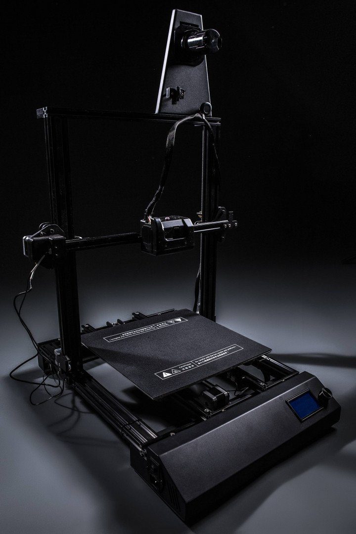
Copymaster 3D Set To Debut First Range of 3D Printers
Reading Time: 5 minutesCopymaster 3D is selling its first 50 3D printers for a 20% discount–meaning you could get one for as low as £399.20. First come first served. Learn more here. Copymaster 3D is a brand new player in the 3D printing world and has certainly raised a few eyebrows since it burst onto…
-

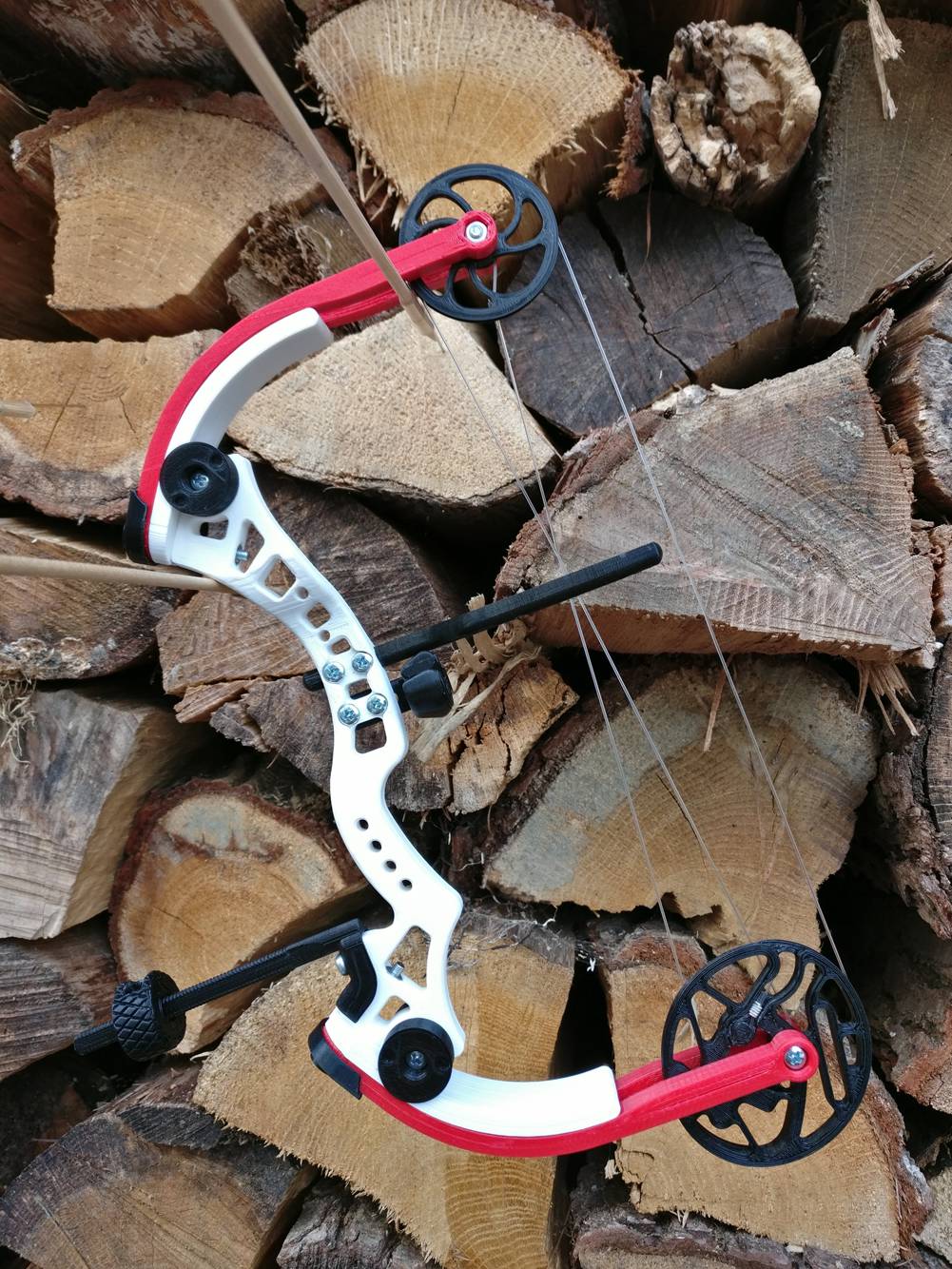
Weekend Project: Take Aim With a 3D Printed Miniature Compound Bow
Reading Time: 3 minutesLooking for an affordable and fun project to round out the summer with? Why not practice your archery skills with a fully 3D printed miniature compound bow. While the world has been expressing an immense amount of concern over the potential rise of 3D printed guns, it’s easy to lose sight of all…
-

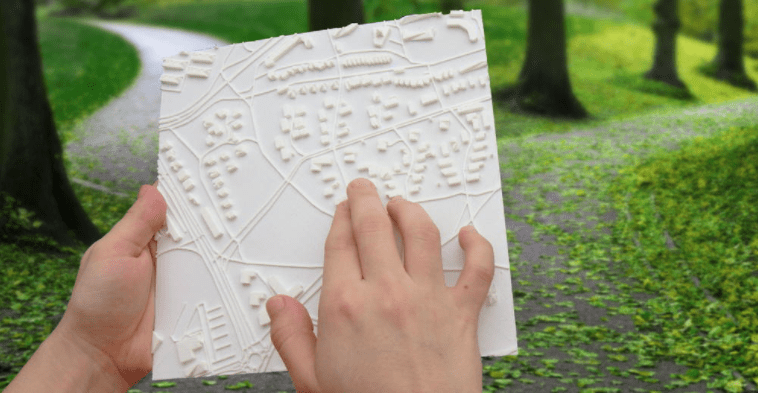
Weekend Project: Make a Customized Map Clock to Celebrate Timeless Memories
Reading Time: 3 minutesRecently shared on the r/3DPrinting subreddit, one maker created an endearing anniversary gift for his girlfriend. This 3D printed clock has a custom 3D map as the face, showcasing the exact area where they first met. You make your own too! Every relationship is special in its own way, and 3D printing…
-

STL File Format (3D Printing) – Simply Explained
Reading Time: 18 minutesWhat is an STL file? What is it good for? How does it work? We simply explain the STL file format for 3D printing in depth. Here’s a primer on what they are and how they work, the advantages and disadvantages of their use, plus alternative file formats to consider. In this…
-

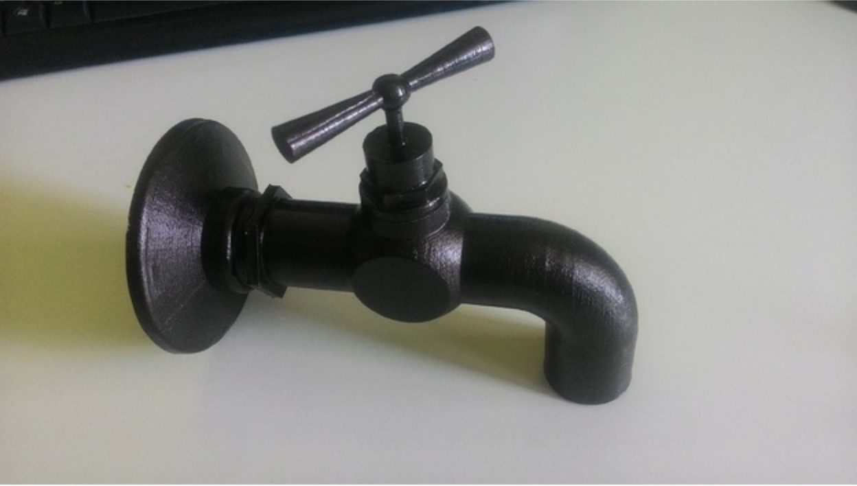
Weekend Project: Amaze Your Friends with a 3D Printed Magic Faucet
Reading Time: 3 minutesA floating faucet? Sounds interesting, doesn’t it? This 3D printed Magic Faucet is a wonderful project for those who love optical illusions. It’s relatively easy to make and simply amazing to look at. In our never-ending endeavor to provide users with fun and useful projects to take on during the weekend, we’ve…
-

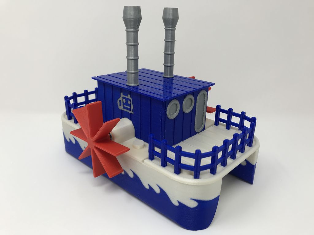
Weekend Project: Have a Pool Party with this 3D Printed Cricket Paddle Wheel Boat
Reading Time: 4 minutesThe Ruiz Brothers of Adafruit are at it again with another fascinating 3D printing project: the 3D printed Crickit Paddle Wheel Boat. This water rover even has an underwater camera mount, so you can capture footage at your end of the summer pool party! As we enter into the final stretch of…
-

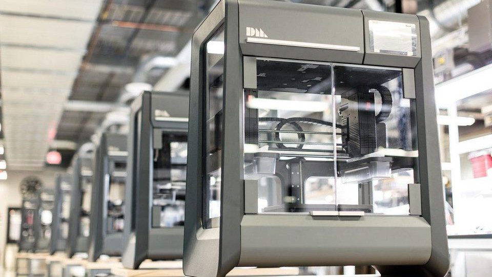
Markforged Cleared of Desktop Metal IP Infringement Claims
Reading Time: 15 minutesIn March, Desktop Metal filed a lawsuit against Markforged for allegedly copying portions of its patented metal 3D printing processes. Last week, a federal jury decided to clear Markforged of both IP infringement allegations, marking a major victory for the defendant. UPDATE (7/30/18) – Court Clears Markforged of IP Infringement Accusations Earlier this…
-

Weekend Project: Get Scientific with this 3D Printed Open Source Laboratory Rocker
Reading Time: 3 minutesNeed some affordable scientific equipment to experiment and make a breakthrough discovery? This 3D printed open source laboratory rocker is a terrific tool for biological and molecular mixing applications. In the scientific setting, a laboratory rocker is used as a mixing device for various biological and molecular applications. It consists of a tray…
-

Weekend Project: Make a Summer Splash with this 3D Printed WiFi Paddle Boat
Reading Time: 4 minutesSummertime is here, and what better way to spend it then by lounging outside by a refreshing body of water. Take your enjoyment of the outdoors a step further by becoming the captain of your own 3D printed WiFi Paddle Boat, designed by Greg Zumwalt. When the heat of the summer hits,…
-

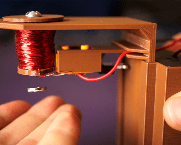
Weekend Project: 3D Print Your Own Magnetic Levitation Device!
Reading Time: 3 minutesInstructables user and designer 3DSage has unveiled an amazing 3D printed Levitation Device that you can make at home. It’s a crazy contraption that uses a magnet to make objects float before your very eyes! For many of us, childhood was marked by amazement when we witnessed our favorite superhero defy the…
-

Archos Airwheel E6 – Dashcam App Review
Reading Time: < 1 minuteTesting the Airwheel E6 in Vienna on the Streets, with the Dashcam Travel App, seems very nice to me. Let me know what you think.
-

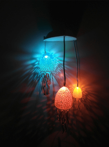
Weekend Project: 3D Print These Seaworthy Voronoi Jellyfish Lights
Reading Time: 3 minutesGive your home an aquatic feel with these incredible 3D printed DIY Voronoi Jellyfish lights created by German maker and Thingiverse user UniversalMaker3D. Who needs IKEA when you have your very own 3D printer? Okay, well sometimes it’s nice to buy some new furnishings and chow down on those Swedish meatballs, but…
-

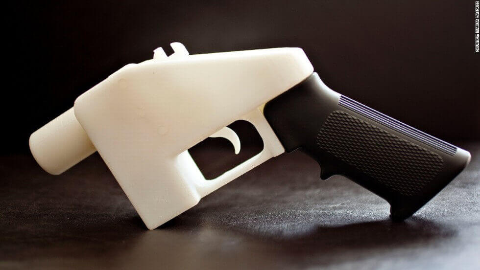
2018 3D Printed Gun Report – All You Need to Know
Reading Time: 14 minutesShould you fear 3D printed guns? Read our 2018 3D printed gun report to learn about the latest news, laws and actual threats to help you sort facts from fears. BREAKING NEWS UPDATE (7-12-2018): After taking the U.S. government to court, Cody Wilson and Defense Distributed have reached a settlement that will allow…
-

Fashion Design Graduate Takes Major Step With Woven 3D Printed Shoes
Reading Time: 3 minutesIn the world of fashion, 3D printing has opened the door for a whirlwind of new looks and styles, and designers have leveraged this technology to showcase just how unique their concepts can be. Fashion design Ganit Goldstein, a fashion design graduate from the Bezalel Academy of Arts and Design in Jerusalem,…
-
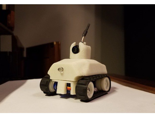
Weekend Project: 3D Print a Servo-Driven Tiny FPV Tank (with a Camera!)
Reading Time: 3 minutesRoll through the upcoming workweek in a servo-driven 3D printed Tiny FPV Tank. This RC model comes equipped with a camera, LEDs, and uses Lego threads to roll around. Spearheaded by projects like OpenRC, the team here at All3DP definitely noticed an increase of interest in using 3D printing to create remote-controlled…
-

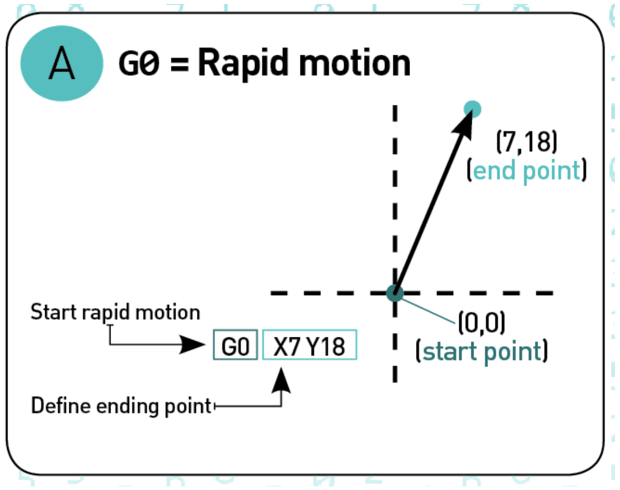
G-Code Commands – Simply Explained
Reading Time: 28 minutesG-code is the programming language of your 3D printer. In this tutorial, you’ll easily learn all G-Code commands. Using G-code, a computer tells a printer when, where, how to move and how much to extrude throughout the entire print process. If you have never dealt with it so far, that’s normal. Slicers…
-

Weekend Project: Turn Back Time with a 3D Printed Delorean Clock From ‘Back to the Future’
Reading Time: 3 minutesHave you always wanted to travel through time like Marty McFly and Doc Brown in ‘Back to the Future’? Well, Great Scott! Now you can with this amazing 3D printed Delorean clock. Originally released in 1985, the critically acclaimed film Back to the Future has proven itself to be timeless, which is a…
-

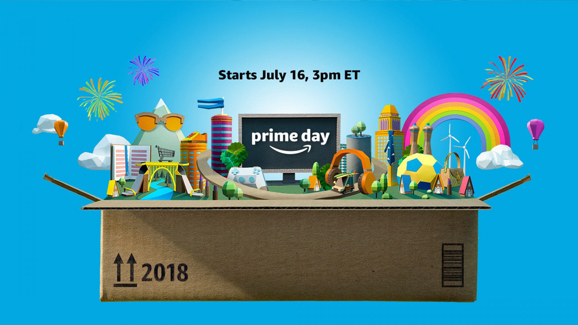
Prime Day is Coming
Reading Time: 2 minutesWell, it’s official. Amazon has updated its homepage with a banner declaring that Monday July 16th is 2018’s Prime Day. We’ll be monitoring it closely to flag any decent 3D printer and 3D printing deals that come up — watch this space. It’s easy to dismiss Amazon’s made-up holiday as a cynical…
-

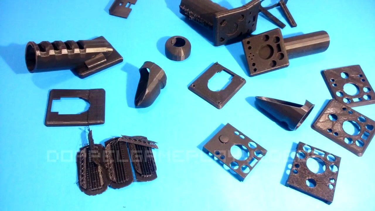
Gamer Uses 3D Printing to Prototype One-Handed PlayStation 4 Controller
Reading Time: 3 minutesA popular YouTuber and gamer named Doppel D has created a 3D printed PlayStation 4 controller that can be used with just one hand, taking accessibility to a whole new level. Whether it be customized accessories for your gaming console of choice or cosplay of your favorite character, 3D printing technology has been…