Instructables user and designer 3DSage has unveiled an amazing 3D printed Levitation Device that you can make at home. It’s a crazy contraption that uses a magnet to make objects float before your very eyes!
For many of us, childhood was marked by amazement when we witnessed our favorite superhero defy the laws of gravity and levitate to the rescue. The concept of levitation is one that seems highly technical or even impossible to some. But that couldn’t be further from the truth, and we’re here to show you how.
One maker named 3DSage has proven that you can bring this phenomenon to reality with your 3D printer and a few components. That’s right…You can make your own Magnetic Levitation Device at home! It might sound like a daunting task, but this project is actually quite easy for beginners and advanced makers alike.
This project is designed for those who lack experience with electronic circuitry and soldering, so don’t be intimidated by the end result. You will need to 3D print a few parts and obtain and handful of components to assemble this Magnetic Levitation Device, so let’s take a closer look at this incredible Weekend Project!
3D Printed Magnetic Levitation Device: What You Need & How to Build
There are eight different parts that need to be 3D printed, all of which are available to download on Thingiverse. The designer suggest printing the parts with 20 percent infill, no support structures necessary. When printing the spool holder parts, 3DSage recommends using a slow print speed.
Other than the STL files, here’s what else you need to create your own 3D printed Magnetic Levitation Device:
Once you have all of your materials, it’s time to get started on the assembly process. 3DSage begins with the 3D printed spool holder and magnet wire. First, place the small 3D printed spool holder inside of the larger one, adding the 4x15mm screw on top. Insert a couple of inches of the wire through the small hole closest to the center of the spool holder and wind the wire tightly.
The next step is the breadboard circuit, which the designer has made as simple as possible. Here’s a diagram to help you follow along:
You have to place the hall sensor in the exact right position to make this levitation device work properly. This is why 3DSage made a breadboard holder so that you can move it around and tune it accordingly. The designer goes into the assembly process in more depth on YouTube, so if you want to learn more about how to created a levitation device, check out the video below!
Special Operation 2, das zweite umfangreiche Update für Ghost Recon Wildlands innerhalb des 2. Jahres startet am 24. Juli und führt den Ghost Modus ein – eine vollkommen neue Art auf die ihr die PVE Kampagne spielen könnt. Außerdem gibt es noch neue Klassen, Karten und Features für den Ghost War PVP-Modus. Natürlich enthält das Update auch noch weitere Überraschungen, wie beispielsweise eine bis dato noch unenthüllte PVE – Mission.
Der Ghost Modus ist sowohl Solo als auch im Koop-Modus spielbar, aber gebt euch keinen Illusionen hin, denn es handelt sich dabei um eine Prüfung eurer Fähigkeiten unter schwersten Bedingungen wie Dauertod, Eigenbeschuss und der Option vollkommen alleine (ohne KI) zu spielen. Weitere Ghost Modus Features beinhalten:
Eine neue Ausstattung die den Spieler auf eine Hauptwaffe und eine Faustfeuerwaffe begrenzt.
Realistisches Nachladen, was bedeutet das, sobald ihr ein nicht komplett verschossenes Magazin aus der Waffe durch ein volles Magazin ersetzt, dass ihr die nicht verschossenen Patronen verliert.
Ausrüstungs-Management welches verhindert, dass der Spieler zwischen verschiedenen Waffen wechseln kann, es sei denn, sie erbeuten diese von ausgeschalteten Gegnern oder Munitionskisten.
Auch Ghost War erhält diverse Updates, darunter zwei neue Klassen, neue Karten – inklusive einer mit verschneiter Umgebung – und neue Features wie zum Beispiel dem Beobachtungsmodus, einem Feature das neben einer frei-schwebenden Kamera und noch weitere Möglichkeiten bietet um eine Runde darzustellen (oder einfach nur anzusehen). Special Operation 2 also führt außerdem Emotes, Siegesposen und Sprachdateien ein, die dem Ganzen noch mehr Persönlichkeit geben werden. Zum Abschluss bietet Special Operation 2 rangbasierte Wettkampforientierte Seasons für Ghost War, die den teilnehmenden Spielern eine weitere Möglichkeit bieten werden, ihre Fähigkeiten unter Beweis zu stellen.
Special Operation 2 erscheint für alle Besitzer von Ghost Recon Wildlands kostenlos, wobei Besitzer des Year 2 Passes, 7 Tage früher Zugang zum Ghost Modus und den neuen Ghost War Klassen erhalten (zusammen mit einiger weiteren Individualisierungs-Packs).
Ghost Recon Wildlands ist bereits für PS4, Xbox Oneund PC erhältlich. Special Operation 2 erscheint für alle Spieler der 3 Plattformen am 24. Juli. Weitere Details zum Spiel findet ihr in unserer bisherigen Ghost Recon Wildlands Berichterstattung.
Diese Woche bekommt South Park: Phone Destroyer Unterstützung auf Android und iOS Geräten, denn das ganze Wochenende über könnt ihr Terrance und Phillip während eines exklusiven Live Events einsammeln. Das Duo kann z.B. innerhalb eurer Schlachten zum Einsatz kommen oder einfach mittels ihrer einzigartigen Fähigkeiten (mächtig-intensive Explosionen waffenfähiger Flatulenzen) Unruhe stiften. Damit gehören nun auch diese zwei zu den bereits 94-Charakteren aus denen ihr eure South Park Favoriten auswählen könnt.
Die Ergänzung durch Terrance und Phillip ist ein weiteres Beispiel für die Zusammenarbeit zwischen Ubisofts Studio RedLynx und South Park Digital Studios. „Wenn es um Updates zu South Park: Phone Destroyer geht, lassen wir uns direkt von der Serie inspirieren“, erklärt Creative Director Justin Swan. „Wenn man bedenkt, wie zeitgemäß die Inhalte sind und wie unmöglich relevant jeder einzelne Witz ist, weiß man nie genau was einen in der nächsten Episode von South Park erwartet. Unser verrücktes Ziel war es, dieses Gefühl auch in Phone Destroyer beizubehalten und rechtzeitig zu den jeweiligen Sendeterminen mit frischen Inhalten aufwarten zu können. Unser Team hat sehr hart daran gearbeitet und ist einer sehr engen Pipeline gefolgt, aber letztlich hat sich die ganze Mühe gelohnt.“
From the outer reaches of space to the small-town streets of suburbia, the hunt comes home in Shane Black’s explosive reinvention of the Predator series.
Now, the universe’s most lethal hunters are stronger, smarter and deadlier than ever before, having genetically upgraded themselves with DNA from other species. When a young boy accidentally triggers their return to Earth, only a ragtag crew of ex-soldiers and a disgruntled science teacher can prevent the end of the human race.
„Erlebt Tom Clancy’s Rainbow Six: Siege hautnah in Düsseldorf! Die besten deutschen Esport-Teams auf dem PC und der PlayStation 4 treffen an einem actiongeladenen Wochenende aufeinander, um zu klären, wer aktuell in Deutschland das beste Team ist.
Die Six Lounge Series sucht dieses Mal bereits zum sechsten Mal einen neuen Meister. Nach Veranstaltungen in Berlin, München und Viernheim ist das Turnier zum ersten Mal in Nordrhein-Westfalen zu Gast. Das komplette Turnier für PC-Spieler startet am Samstag ab 14 Uhr, inklusive eines neuen Rahmenprogrammes. Die Finalspiele starten am Samstag ab 17 Uhr. Dazu gibt es nach dem Finale eine Get-Together-Party, zu der alle Gäste herzlich eingeladen sind. Eine Registrierung über Eventbrite garantiert den Einlass für die Abendveranstaltung. Zulass vor Ort gibt es nur so lange der Vorrat reicht. Am Sonntag starten ab 14 Uhr die PlayStation-4-Teams durch und küren den Sieger der dritten Siege Masters. Eine Registrierung ermöglicht euch den kostenlosen Eintritt zu beiden Veranstaltungen.
In der Glühofenhalle sowie im Livestream begrüßen euch wie gewohnt als Host Robin „RhinozeRob“ Rottmann sowie die das deutsche Rainbow-Casterteam rund um Marius „verdipwnz“ Lauer, Tobias „ShatterXx“ Richter, Ihno „Harris“ Kampen, Philip „ScorpyR6“ Nesemann und Lucian „Agony“ Kohn.
Erlebt den Nervenkitzel des Finales live in Düsseldorf oder seht euch den Livestream auf unserem offiziellen Twitch oder YouTube Kanal an.
Warhammer: Vermintide 2 is the sequel to the critically acclaimed Warhammer: End Times – Vermintide. Fight together with your friends against the forces of Chaos and Skaven in this epic 4-player co-op game set in the Warhammer Fantasy Battles world.
Asmodee Digital, einer der Marktführer im Bereich digitale Brettspiele, hat heute seine Präsenz auf der gamescom 2018 angekündigt. Vom 21. bis zum 23. August präsentiert der Publisher dort am eigenen Stand im Business-Bereich die für Winter 2018 angekündigte Switch-Version des Brettspielklassikers Carcassonne, sowie exklusive neue Informationen zum Lovecraft-Adventure Mansions of Madness: Mother‘s Embrace und spannende Neuankündigungen. Außerdem wird es Neuigkeiten zu Asmodee Digital-Spielen auf Konsole geben.
Scythe ist ein asymmetrisches, kompetitives Brettspiel, das in einem alternativen 20er-Jahre-Stil stattfindet. In Scythe repräsentiert jeder Spieler einen gefallenen Anführer, der versucht, seine Ehre wiederherzustellen und seine Fraktion an die Macht in Osteuropa zu führen. Spieler können Territorien erobern, neue Rekruten und Dorfbewohner gewinnen, Ressourcen ernten, Strukturen bauen und monströse Mechs aktivieren.
Die Digital Edition von Scythe stellt eine KI vor, die die Automatas ablöst und die Besonderheiten der einzelnen Fraktionen ausschöpft. Gleichzeitig werden die Buchhaltungsaufgaben optimiert. So bleibt das bekannte Scythe-Gameplay in der digitalen Version erhalten und wird gleichzeitig für Neueinsteiger zugänglich gemacht. Zu den weiteren neuen Funktionen gehören eine speziell entwickelte Benutzeroberfläche, ein Ingame-Chat und Lobby-Systeme.
Action, Spannung und Abkühlung – das coole Programm am Feiertag.
Als einige Teenager auf mysteriöse Weise beginnen, mächtige, übernatürliche Kräfte zu entwickeln, werden Sie von der Regierung als Bedrohung erklärt und inhaftiert. Die sechzehnjährige Ruby, eine der stärksten und mächtigsten der Jugendlichen, flieht aus dem Camp und stößt zu einer Gruppe durchgebrannter Teenager, die auf der Suche nach einem sicheren Ort sind.
Bald muss die neu gefundene Familie feststellen, dass es in einer Welt, in der die mächtigen Erwachsenen sie betrogen haben, nicht reicht nur wegzulaufen. Die Teenager müssen den Kampf aufnehmen, um sich durch vereinte Kräfte die Kontrolle über Ihre Zukunft zurück zu holen.
1 x das Buch zum Film The Darkest Minds – die Überlebenden
5 x Knicklichter von Molino
Was ihr tun müsst um mitzumachen findet ihr weiter unten.
Basierend auf der Buchreihe von Alexandra Bracken. Nachdem eine Krankheit den Verlust von 98% der Amerikanischen Kinder forderte, entwickeln die überlebenden 2% Superkräfte und werden in Internierungslager gesperrt. Ein 16-jähriges Mädchen kann aus dem Lager entkommen und schließt sich einer Gruppe Teenagern an, die auf der Flucht vor der Regierung sind.
GENRES
Science-Fiction | Thriller / Spannung
Cast & Crew
Amandla Stenberg
Gwendoline Christie
Mandy Moore
Jennifer Yuh Nelson
ab 15. August nur im Kino
Folgt uns auf Instagram und kommentiert auf unser Gewinnspiel Post, unter allen die mitmachen suchen wir einen dann aus.
Der DLC Lost On Mars setzt die unheimlichen Abenteuer im Far Cry 5-Season Pass fort und lässt Spieler als Nick Rye gemeinsam mit Hurk zum Mars reisen, um eine Alien-Bedrohung auszuschalten. Lost on Mars kann eigenständig als DLC, als Teil des Far Cry 5-Season Passes, oder als Teil der der Gold Edition erworben werden.
Far Cry 5: Lost on Mars teleportiert den Wahnsinn der Reihe aus dem beschaulichen Hope County hinauf auf den roten Planeten. Dort müssen Nick Rye und Hurk die futuristische KI ANNE wieder in Betrieb bringen, da sie die letzte Verteidigungslinie der Menschheit ist. Den Spielern stehen dabei neue Waffen aus dem Arsenal der Außerirdischen zur Verfügung, darunter:
Blaster of Disaster: Eine Einzelschuss-Raumkanone hergestellt aus zuverlässiger Alien-Technologie
Hellfire: Feuert 15 Laserbälle ab, die schwere Schäden verursachen.
Morphinator: Mit der Kraft der Wissenschaft werden Jäger zu Gejagten – inklusive einer explosiven Überraschung
Space Jets: Völlig schwerelos über den Mars springen und auf völlig neue Art das außerirdische Terrain erkunden
Zusätzlich zum DLC haben ab heute alle Far Cry 5-Spieler in der Far Cry Arcade Zugang zu Lost on Mars-Inhalten. Karten-Ersteller können diese fortan in ihren Kreationen nutzen und so futuristische Science Fiction-Settings erstellen.
Ubisoft veröffentlichte außerdem den Soundtrack Far Cry 5: Lost on Mars, eine funky, Science-Fiction, 70er Jahre inspirierte Spaghettiwestern-Track-Liste, die vom Filmkomponisten Anthony Marinelli kreiert und aufgeführt wurde. Marinelli verwendete die Vintage-Analog-Synthesizer der Kultfilme Young Guns, Starman, War Games und Michael Jacksons Thriller, sowie Sci-Fi-Orchesterriffs, Baritongitarre, Banjo, Dobro, Wah-Gitarre und funky Basslinien, um die Spieler mit dem Groove zu fesseln. So wie es Spinnen auf dem Mars tun würden. Der Soundtrack ist hier verfügbar: https://idol.lnk.to/FarCry5_Lost_On_Mars
Give your home an aquatic feel with these incredible 3D printed DIY Voronoi Jellyfish lights created by German maker and Thingiverse user UniversalMaker3D.
Who needs IKEA when you have your very own 3D printer? Okay, well sometimes it’s nice to buy some new furnishings and chow down on those Swedish meatballs, but you can also go the DIY route and produce your own stylish and decorative objects to spruce up the home. One common use for 3D printing is to create custom lighting fixtures, and we’ve seen a myriad of great ideas across the maker-sphere.
German student and Thingiverse user UniversalMaker3D has recently designed free-floating Jellyfish lights. The design is inspired by the mathematically-driven design concept of Voronoi, which provides a complex structure to the 3D printed sea creature.
The Voronoi design gives a coral reef-like impression, adding to the oceanic vibe that these jellyfish lights conjure up. The 3D printed shell is embedded with a number of tiny holes, creating a jaw-dropping lighting effect on your walls. Add some tentacles to the mix and you’ve got yourself a lighting fixture that will have you feeling as if you’re living under the sea.
3D Printed Voronoi Jellyfish: What You Need & How to Build it
Since the jellyfish-like lighting enclosure is designed in the complex Voronoi style, you’ll need to use supports when 3D printing the base of the model. UniversalMaker also shares the STL files for the tentacles and other parts, all of which are freely available on Thingiverse.
Aside from your 3D printer, filament and the 3D model, there’s still some other components you’ll need to make your sea creature lamp light up. Here’s the checklist:
Once you have your 3D printed jellyfish body and tentacles, along with all of the necessary electronic components, it’s time to put everything together. Take the LEDs and run them through the bottom of the 3D printed top and connect it via the switch to the battery.
The 3D printed top and bottom sections are designed to slide perfectly over each other, but might require a bit of sanding. Finally, mount the jellyfish with the cables, which are used to activate the LEDs. That’s about it as far as assembly goes! If you want to catch a visual of how awesome these 3D printed jellyfish lights look, check out the designer’s instructional video below.
Should you fear 3D printed guns? Read our 2018 3D printed gun report to learn about the latest news, laws and actual threats to help you sort facts from fears.
BREAKING NEWS UPDATE (7-12-2018):After taking the U.S. government to court, Cody Wilson and Defense Distributed have reached a settlement that will allow the organization to re-upload 3D printable gun models to their website. Learn more about this potentially landmark decision on All3DP.
Both makers and lawmakers around the world have taken notice of 3D printed guns. Regardless of intention, their efforts to stifle the use of 3D printed firearms have given rise to a number of difficult questions.
Should someone with the files for a 3D printed gun be charged with the same crime as someone that actually has the gun? Has the media sensationalized the rise of 3D printed guns? What’s the best way to regulate 3D printed weapons? And most importantly, should you fear 3D printed guns?
To answer these questions, we will examine the reasons why you should and shouldn’t fear the 3D printed gun, explain the history, and then go over the laws that have been put in place to stop them.
The 3D Printed Gun: All You Need to Know Right Now
Exhibit A: The Liberator
Reasons to Fear & Not to Fear 3D Printed Guns
There are valid arguments for why you should and shouldn’t fear 3D printed guns, making this quite the loaded issue. To offer a fair and balanced view on this controversial topic, we’ll offer reasons on both sides of the 3D printed gun debate to help you decide for yourself.
Why You Should Fear
From CNN to Gizmodo, mainstream media outlets have focused more on 3D printed firearms than any other innovative application of this wide-ranging technology. But where does this fear stem from?
Perhaps what stirs this fear isn’t the functionality of these homemade weapons, but the ease of creating one without anyone knowing. Many states in the U.S. and other countries throughout the world have strict gun control laws. Generally speaking, those who are allowed to own a firearm must have it registered. But with 3D printed guns, people fear that criminals and other unstable people will be able to produce firearms at home and commit crimes with it.
Although the current state of desktop 3D printing doesn’t necessarily allow high-quality firearms to be manufactured at home, this could also change as the technology advances. For instance, as metal 3D printing becomes more affordable and accessible, the potential to create higher-grade weapons could grow.
Another valid fear is that 3D printing could lead to cheap firearm factories for criminals. But again, having a gun 3D printed in metal would cost thousands of dollars, making it more convenient for criminals go to through other illegal channels to find one.
Needless to say, it’s not a 3D printed gun that should be feared. If anything, it’s the idea of being able to manufacture firearms unchecked that really drives this frenzy forward.
Why You Shouldn’t be Concerned
It’s quite easy to produce a plastic firearm with the proper 3D files and desktop printer. But this homemade 3D printed gun is far from reliable when it comes to functionality. In fact, police testing has proven that a 3D printed gun could endanger the shooter as much as anyone else.
A firearm produced with ABS material could break apart or even potentially explode in the hands of the user when fired. Softer PLA will likely cause the parts to bend or deform after firing.
Realistically, neither ABS or PLA is ideal for producing firearms. While most 3D printed guns are made using ABS, chances are only a single shot will be able to be fired before it either breaks or fails. The reason for this is because the act of firing a bullet simply exerts too much power for most thermoplastics to withstand.
Some gun enthusiasts have created hybrid 3D printed guns, consisting of traditional metal components and thermoplastics. In theory, these firearms should offer much better functionality than an ABS-based weapon. But again, building a hybrid 3D printed gun seems counterproductive to just finding an actual one.
Lastly, metal 3D printing can and has been used to produce a fully functional firearm. There’s no denying this. But, these type of prints are extremely costly, and it makes no sense for a criminal to go to a metal 3D printing service instead of finding a cheaper and more discreet way on the black market.
This also helps to quell the fear that a 3D printed gun would be able to slip through a metal detector, seeing that at least a metal firing pin would be needed to make the makeshift firearm functional. 3D printed guns that are comprised primarily of thermoplastic are extremely ineffective and thus aren’t worth the trouble of manufacturing cases where they will be used in a menacing way.
Essentially, there is no reason to fear a 3D printed gun any more than you would a traditionally manufactured one. In fact, in the United States, actual firearms are easier to get and are much more lethal. There are approximately 300 million firearms spread across the U.S., making the potential 3D printing gun epidemic pretty pointless.
As you will see later in this article, the threat level of a 3D printed gun is much higher in places with strict gun control, especially Australia.
A Brief History of the 3D Printed Gun
The 3D printed gun components that make up the Liberator.
The world’s first functional 3D printed gun was designed back in 2013 by Cody Wilson, a crypto-anarchist and the founder of the Texas open source gunsmith organization Defense Distributed. The 3D files for this one-shot pistol were the first to be released into the world. They sparked an unprecedented controversy that still looms over the 3D printing community to this very day.
After the files for the Liberator were downloaded over 100,000 times in two days, the US Department of State compelled Defense Distributed into taking the model down. This demand has sparked an ongoing legal battle between the techno-anarchist and government.
Most of the 3D printed guns that have surfaced thus far are pistols. But even semi-automatic weapons have been released by Defense Distributed – and confiscated by police.
As 3D printed gun blueprints are distributed by the internet, they have been found across the world, from Australia to Japan, Europe to the Americas. These makeshift firearms have found their way into the hands of police, criminals, and libertarians alike.
Since the release of the Liberator, many government bodies have been scrambling to impose laws that would strictly prohibit 3D printed guns, and in some cases even 3D models of firearms.
Nowadays, additively manufactured weapons remain an unknown threat, but countries like Australia and the United States are not wasting any time in fear-mongering and passing laws.
Most 3D printed guns are based off previously existing designs. Most of them are freely available to download, but also hard to find due to increasing illegality. But when Defense Distributed’s Liberator first hit the scene, it proved that a firearm could be produced almost entirely out of thermoplastic material.
Every component of Wilson’s Liberator was 3D printed except for the metal firing pin and the actual bullet. As you can see in the photo below. The Defense Distributed founder has also created an automatic weapon that is not fully 3D printed but is equipped with additively manufactured components, in the past.
Since then, Wilson has continued on his campaign to put DIY firearms in the spotlight. After his 3D model was forced off the internet, Defense Distributed released the Ghost Gunner, a desktop CNC milling machine designed to manufacture guns. At first, the machine was only capable of producing the lower receiver component for an AR-15. However, Wilson recently upgraded the Ghost Gunner software to make it capable of creating the aluminum frame of a M1911 handgun.
While Wilson believes that he is advocating for gun rights by making firearm production more accessible and undetectable, others have grown worried about this technology getting into the wrong hands. Across the world, countries are passing laws that equate 3D printed guns with traditional firearms. In some places, even having the 3D model for a firearm would be considered possession of an illegal weapon.
Now that we’ve shared a brief history of 3D printed guns with you, let’s take a look at the laws that have been drawn up to prevent people from 3D printing their own firearms.
Defense Distributed wants the 3D printed gun to be treated the same as regular weapons in the US (image: Marisa Vasquez)
3D Printed Gun Laws in the United States of America
After the Liberator was deemed in violation of the International Traffic in Arms Regulations (ITAR), Wilson filed a federal civil suit against the State Department. To this very day, Wilson is still fighting for his right to publish his 3D printable firearm files.
In September 2016, the United States Court of Appeals for the Fifth Circuit rejected his preliminary injunction request, claiming that national security concerns outweigh Defense Distributed’s First Amendment right to freedom of speech.
Even though the State Department has succeeded to keep 3D gun files illegal in court, Wilson’s design and a handful of others have seeped through the cracks of the internet. There have been a number of instances where 3D printed guns have been confiscated by police the US.
In August 2016, Transportation Security Administration (TSA) at the Reno–Tahoe International Airport found a 3D printed gun and five .22-caliber bullets in a passenger’s carry-on bag. The year prior, two felons in Oregon were caught with an assault rifle that had a 3D printed lower receiver attached to it.
It is illegal under the Undetectable Firearms Act to manufacture any firearm that cannot be detected by a metal detector. 3D printed guns are usually made from PLA or ABS and are therefore not allowed in the US, as legal designs for firearms require a metal plate to be inserted into the printed body.
Some states that allow firearm ownership have taken up the issue of 3D printed gun themselves. For example, California passed a law that requires a 3D printed gun to be properly approved and registered. But with relatively lax gun laws in a number of US states, 3D printed guns have proven to be a more glaring problem in Australia, which has much stricter anti-gun legislation.
All in all, when it comes to producing or obtaining weapons in an unlawful manner, 3D printing is far from preferable, at least in the current state of the technology. Criminal organizations may look towards 3D printing more often as the technology advances, but for now, most of the fear seems unjustified. At the end of the day, where there’s a will, there’s a way.
3D Printed Gun Laws in Australia
Exhibit B: A haul by the New South Wales Police in Australia
No country has encountered as much legal trouble with 3D printed guns as Australia has. Their strict firearm legislation has limited the access to traditional weapons. So some have turned to 3D printing to help circumvent the law.
In November 2016, Gold Coast police discovered a highly sophisticated weapons production facility that used 3D printers to produce machine guns. A month later, a collection of 3D printed firearms were seized in Tasmania, but the manufacturer was let off with a warning. Perhaps Australia’s most concerning case, police recently linked the discovery of 3D printed guns in Melbourne to the Calabrian mafia.
To combat the rise of 3D printed guns, New South Wales passed a law equating possession of 3D gun files to actual possession of a 3D printed gun. Some of Australia’s Senate members have their doubts about 3D printed guns being an imminent threat, and that further restrictions would hinder 3D printing innovation overall. The country’s Green Party has been a staunch opponent to 3D printed guns, citing the growth of the technology as proof that 3D printing will be capable of producing more dangerous weapons soon.
In 2013, New South Wales police tested out a 3D printed gun. With this handgun, they were able to fire a bullet 17 centimeters into a standard firing block, but the plastic exploded when the bullet was discharged.
In 2015, the county amended its firearms act to include a clause that says “A person must not possess a digital blueprint for the manufacture of a firearm on a 3D printer or on an electronic milling machine… [or face a] Maximum penalty: imprisonment for 14 years.”
But the situation in Australia is trickier than most. The glaring amount of confiscated 3D printed weapons seems to be linked to the country’s strict laws, making traditional metal firearms much more difficult to come across than they are in the US. It’s important to note that while a plastic 3D printed gun poses a minimal risk, most Australian legislators fear the increasing accessibility and affordability of metal 3D printers will come back to haunt them.
3D Printed Gun Laws in Europe and United Kingdom
Contrary to Australia, the strict gun control laws in Europe have reduced the threat of 3D printed guns. Still, when you look at the regions that downloaded the Liberator files the most, you’ll find that most of the leading countries are located in Europe. During the two initial days Wilson’s infamous 3D printed gun was available online, it was downloaded the most in Spain, followed by the US, Brazil, Germany, and the United Kingdom.
The United Kingdom has been particularly concerned with the rise of 3D printed guns, calling them a threat to national security. In 2013, theUK Home Office introduces stricter regulations on 3D printed guns or gun parts, making it highly illegal to create, buy, or sell them in Great Britain.
Thus far, the threat of 3D printed guns in Europe has mostly been confined to television. The Italian crime TV series Gomorra recently depicted a RepRap 3D printer being used to create a 3D printed gun.
3D Printed Gun Laws in Asia and the Middle East
The ZigZag pistol from Yoshitomo Imura.
The 3D printed gun controversy isn’t just restrained to the western world. Shortly after Wilson’s design surfaced, Japanese citizen Yoshitomo Imura designed and printed a six-shot revolver known as the ZigZag. The government ended up sentencing him to two years in prison for 3D printing guns and also instructing others.
China has also taken extreme measures to monitor and prevent 3D printed guns and other weapon from surfacing. Police in Chongqing are requiring all companies with 3D printers to register themselves as “special industries”, asking for the equipment in use, the security measures they have in place, and even information on all employees.
While police in China certainly fear the potential rise of the 3D printed gun, other citizens feel that the law is an overreaction. According Kwok Ka Wai, assistant professor in the mechanical engineering department at the University of Hong Kong, there are practical limitations on using 3D printing to manufacture weapons or other items protected by copyright.
“There are a lot of tools that you can use to make bad things, but they are not tailor-made for that purpose,” he says.
Although they’re the most focused on, 3D printed guns are far from the only weapon that 3D printing can potentially be used to manufacture. Concerns have also mounted in the Middle East over the possibility that ISIS is using 3D printing to produce bombs.
3D Printed Guns on the Dark Net
With the distribution of 3D gun models illegal across the world, these 3D gun models have found a home on the dark net. Sold alongside traditionally manufactured firearms and other black market weapons, 3D printable gun designs are being distributed more and more through the deep web.
A recent study from the non-profit research organization RAND Corporation discovered a startling rise in 3D gun models. While looking at the entire dark net market for weapons, the researchers found that 11 of the for-sale items were CAD files for firearms.
Now, it’s clear that CAD models are still way less threatening than the physical firearms sold on the black market, but the mere presence hints at a potentially dangerous situation in the future. What stood out the most to the RAND research team is the average cost of 3D gun models. While the average gun costs $1,200 on the dark net, a price for a 3D printable gun design averages out to $12.
Not only is the cost for these CAD models extremely low, but such files can be sold over and over again. Therefore, if and when the day comes where metal 3D printers become more affordable, it’s possible that this minor issue could start to loom larger.
The 3D Printed Gun: Conclusion
There’s no denying that 3D printed guns are being discovered in different parts of the world. They are getting more popular in Australia and US. But are these makeshift weapons really the treat the media portrays them to be? Ultimately, the answer seems to be yes, but more so no.
The current lack of access to affordable metal 3D printing makes producing a functional 3D printed gun solely with plastic difficult. But for most firearm components, this emerging technology could soon become a viable option for gunsmiths, gun advocates, and even criminal organizations. Also, the materials you can 3D print with are getting better and better.
At this point, there have been no violent crimes attributed to a 3D printed gun. But still, a more realistic threat will likely arise when access to metal 3D printingincreases in the near future.
At the moment, it’s easy to dismiss anti-3D printed gun legislation as overreaching and embellished. But that doesn’t mean that various laws preventing the production and sharing of 3D printed guns don’t have any merit. Just as with any other youthful technology, 3D printing will continue to advance and become more affordable.
Needless to say, the fear-mongering campaign on 3D printed guns is way overblown, especially for the time being. While this emerging technology is providing incredible benefits to the medical, industrial, and consumer sectors, all the mainstream media seems interested in is making it seem like weapons are falling out of your 3D printer’s extruder.
At the end of the day, there’s no reason to fear a 3D printed gun any more than you would a conventionally manufactured or CNC milled firearm. Desktop 3D printers are not capable enough to create a lethal weapon on their own, and metal 3D printed guns are far too expensive to appeal to criminals.
There’s a reason that no violent crimes involving 3D printed guns have been reported. They’re unreliable, difficult to produce, and in most places, are harder to come across than a black market firearms. Regardless of your view on the right the bear arms, there’s no reason to lump in a technology that does much more good than harm.
In the world of fashion, 3D printing has opened the door for a whirlwind of new looks and styles, and designers have leveraged this technology to showcase just how unique their concepts can be.
Fashion design Ganit Goldstein, a fashion design graduate from the Bezalel Academy of Arts and Design in Jerusalem, has recently unveiled a collection of 3D printed clothing and shoes.
Goldstein’s “Between the Layers” collection consists of seven outfits and six pairs of shoes, all of which were created using 3D printing. By bridging the boundaries between modern manufacturing technology and traditional fashion design, Goldstein has created a range of unique pieces. The collection is a part of Goldstein’s graduation project, fusing additive manufacturing with traditional crafts such as weaving.
“My work begins with the design and production of digital objects that serve as a three-dimensional object. […] I then weave handmade threads in a unique manner to each object,” she explained in an email.
The inspiration behind this collection arose when Goldstein visited Japan as part of an exchange program at the Tokyo University of the Arts. During her stay abroad, she had the opportunity to learn a traditional Japanese textile technique called IKAT weaving.
Upon her return to Israel, she began to develop a weaving process using an Orginal Prusa i3 Mk3 3D printer. She then finished off the designs by adding hand-woven layers.
Intel collaboration highlights process behind the designs
Goldstein also worked in collaboration with the tech giant Intel, using the company’s 3D scanning technology as a part of the project. Specifically speaking, she developed an Augmented Reality app that showcases the process behind his 3D printed shoes and clothing.
One of the shoes in the collection was produced with the Stratasys Connex 3 printer. The latter provides multi-color printing capabilities.
“My work begins by examining the characteristics of the material, the qualities with which I can work with,” she explained. “Working with 3D software gives me the freedom to test which boundaries can be broken. [It provides] the understanding that the connection to the traditional craft material will create a completely new essence to the original material. For example, the technique of 3D layer printing allows me to re-examine which layers can be added and what new connections I can create.”
Overall, the final collection accomplishes an interesting balance between modern technologies and traditional fashion design.
Roll through the upcoming workweek in a servo-driven 3D printed Tiny FPV Tank. This RC model comes equipped with a camera, LEDs, and uses Lego threads to roll around.
Spearheaded by projects like OpenRC, the team here at All3DP definitely noticed an increase of interest in using 3D printing to create remote-controlled cars, planes, drones and boats. While we’ve featured a handful of these fun hobbyist-type projects in our Weekend Project series, few of them pack a compact punch like this Tiny FPV Tank designed by Thingiverse user RotorGator.
Not only is this servo-powered tank small, it also implements Lego threads, a tiny FPV camera and LEDs. It might not be battle-ready, but this miniaturized tank will provide you with a fun way to inconspicuously cruise around and film all of life’s top-secret missions.
Let’s take a look at what you need to put together your own 3D printed Tiny FPV Tank.
3D Printed Tiny FPV Tank: What You Need & Putting it Together
This Tiny FPV Tank is comprised of a handful of 3D printed parts, but RotorGator has split the body into six sections: the chassis, frame, two drive wheels, two non-drive wheels, two non-drive spacers and the FPV camera mount. Use of support structures is only necessary for a few parts if you decide to print them whole, otherwise you can go support-less by printing the wheels and frame in halves.
Although the body of this tank is heavily based around 3D printing, you’ll still need a handful of components to put this armored vehicle into action. Here’s what else you need besides your 3D printer:
The details on the assembly process are sparse, but the build seems relatively easy. Here’s how the designer lays things out on the Thingiverse page.
Once you have the parts 3D printed, remove any supports before you start putting it together. Cut off the servo arm in order to fit it snugly into the driven wheel and attach it using the supplied screw. Using M3 bolts and spacers, mount the non-driven wheels. If you decided to print the parts in halves, use super glue to put them together. The 3D printed frame and chassis should snap together quite easily. Finally, use a bit of super glue to attach the FPV pod to the top of the tank’s frame.
G-code is the programming language of your 3D printer. In this tutorial, you’ll easily learn all G-Code commands.
Using G-code, a computer tells a printer when, where, how to move and how much to extrude throughout the entire print process.
If you have never dealt with it so far, that’s normal. Slicers like Cura and Simplify3D generate G-code “automagically” from CAD models, so most users never see or program a single line of code. However, if you want to develop a deeper understanding of 3D printing, it is essential to know about this programming language.
A knowledge of G-code commands will give you 3D printing superpowers. People who this are able to troubleshoot their printers better, control every aspect of the print process and identify and prevent print failures much before they happen.
If that sounds interesting, this post is for you. Our aim is to get you started with the basics. After reading this post, you will be able to:
Read and understand G-code commands
Write it yourself and test it online
Use the preview functionality of Slicers to troubleshoot complicated prints
Let’s get started!
What are G-code Commands?
G-code stands for “Geometric Code”. Its main function is to instruct a machine head how to move geometrically in 3 dimensions. However, it can also instruct a machine to do non-geometric things. For example, G-code commands can tell a 3D printer to extrude material at a specified extrusion rate or change its bed temperature.
In formal terms, it is a numerical control programming language. For those who know how to program, it’s an easy programming language. It is rudimentary and does not have advanced constructs like variables, conditionals, and loops.
For those who don’t know about programming languages, you can think of G-code as sequential lines of instructions. Each line tells the printer to do a specific task. The printer executes the line one by one until it reaches the end.
How to read G-code Commands
So, how does a line of code look like? Here is a typical example:
G1 X-9.2 Y-5.42 Z0.5 F3000.0 E0.0377
This particular line tells the printer to move in a straight line towards the destination coordinates X=-9.2, Y=-5.42, and Z=0.5 at a feed rate of 3000.0. It also instructs the printer to extrude material at a rate of 0.0377 while it is moving.
How did we read and interpret that? It’s quite easy. Every line starts with a command. In this case, the command is G1.
G1 X-9.2 Y-5.42 Z0.5 F3000.0 E0.0377
It means “move in a straight line in a controlled fashion”. You can look up the meaning of every G-Code command in a table that we have provided at the end of the article. We will also go through the most important G-Code commands in a later section.
The code snippets that appear after the command are called arguments.
G1 X-9.2 Y-5.42 Z0.5 F3000.0 E0.0377
Each argument tells the printer about how to execute the command. The arguments start with an English letter and then specify a value. For example, X-9.2 means a destination X coordinate of -9.2. F3000.0 means a Feed rate(F) of 3000.0. E0.0377 means an Extrusion rate(E) of 0.0377.
Try reading the following line of code now.
G1 X5 Y5 Z0 F3000.0 E0.02
If you interpreted it to mean “move towards X=5, Y=5, and Z=0 in a straight line at a feed rate of 3000.0 while extruding material at the rate 0.02”, then you have already learned how to read G-code commands!
G-code commands which start with the letter G are geometric commands. They tell the printer head how to move, but this is clearly not enough to control all aspects of a 3D printer. What if you needed to tell the printer to turn the motor off or raise the bed temperature? For these non-geometric tasks, G-code implementations also define another set of commands which start with the letter M. They are aptly called M Codes. For example, the command M140 sets the bed temperature, and the command M190 tells the printer to wait for the temperature to reach the target.
Each English letter that you encounter in the code will have a specific meaning. For example, we learned that G means a geometric command, M means a non-geometric command, X means the X coordinate, Y means the Y coordinate, F means Feed rate and so on. For your reference, here’s a table with the meaning of every letter.
Code
Information
Gnnn
Standard GCode command, such as move to a point
Mnnn
RepRap-defined command, such as turn on a cooling fan
Tnnn
Select tool nnn. In RepRap, a tool is typically associated with a nozzle, which may be fed by one or more extruders.
Snnn
Command parameter, such as time in seconds; temperatures; voltage to send to a motor
Pnnn
Command parameter, such as time in milliseconds; proportional (Kp) in PID Tuning
Xnnn
A X coordinate, usually to move to. This can be an Integer or Fractional number.
Ynnn
A Y coordinate, usually to move to. This can be an Integer or Fractional number.
Znnn
A Z coordinate, usually to move to. This can be an Integer or Fractional number.
U,V,W
Additional axis coordinates (RepRapFirmware)
Innn
Parameter – X-offset in arc move; integral (Ki) in PID Tuning
Jnnn
Parameter – Y-offset in arc move
Dnnn
Parameter – used for diameter; derivative (Kd) in PID Tuning
Hnnn
Parameter – used for heater number in PID Tuning
Fnnn
Feedrate in mm per minute. (Speed of print head movement)
Rnnn
Parameter – used for temperatures
Qnnn
Parameter – not currently used
Ennn
Length of extrudate. This is exactly like X, Y and Z, but for the length of filament to consume.
Nnnn
Line number. Used to request repeat transmission in the case of communications errors.
*nnn
Checksum. Used to check for communications errors.
Now that you know how to read a line of code, let’s look at a simple example in action. The following video shows G-code commands at work in a cutting machine (not a 3D printer). The cutting machine will cut a circular edge in a rectangular slab. The G-code commands instruct the cutter on how to move to achieve the desired result.
Do not worry that the video is about a cutting machine. The geometric aspects of G-code commands work similarly for all machines that have a machine head. In the case of the 3D printer, the nozzle is the head. For the cutting machine, the head is the cutter. That’s the only difference. All other geometric aspects of the code remain the same.
If you understand the cutter’s movements, you will also know how to move a print head.
The most important G-code Commands
In the last section, we discussed the G1 command, which means “move the nozzle in a controlled fashion in a straight line”. This is just one of the many G-code commands. In this section, we will discuss other important commands that are used frequently.
G-code commands #1: G0 or “rapid motion”
The G0 command tells the print head to move at maximum travel speed from the current position to the coordinates specified by the command. The head will move in a coordinated fashion such that both axes complete the travel simultaneously. The nozzle will not extrude any material while executing this command. This G-code command is usually used to bring the nozzle rapidly to some desired coordinates at the start of the print or during the print.
Example: G0 X7 Y18
Image: Make Magazine
G-code commands #2: G1 or “controlled motion”
The G1 command tells the print head to move at specified speed from the current position to the coordinated specified by the G-code command. The speed is specified by the Feed rate parameter F. The head will move in a coordinated fashion such that both axes complete the travel simultaneously. The printer can extrude material while executing this G-code command at an extrusion rate specified by the extrusion rate parameter E. Most of the 3D printing happens while executing this command. If you open the G-code file for an actual 3D printing process, you will see a lot of G1 commands.
Example: G1 X7 Y18 F500 E0.02
Image: Make Magazine
G-code commands #3: G17/G18/G19 or “set planes”
These G-code commands set the plane in which the nozzle should move. Typically, G17 is the default for most machines and it denotes the X-Y plane. G18 denotes the Z-X plane and G19 denotes the Y-Z plane.
G-code commands #4: G20/G21 or “set units”
These G-code commands set the units. G20 denotes inches while G21 denotes millimeters. This makes a big difference because
G20

G0 X7 Y18
means “move rapidly to X=7 inches and Y=18 inches” while
G21

G0 X7 Y18
means “move rapidly to X=7 mm and Y=18 mm”.
G-code commands #5: G28 or “homing”
A G28 command tells the machine to go to its home position. A home position can be defined by the G28.1 command as follows.
G28.1 X0 Y0 Z0
G-code commands #6: G90 or “absolute mode”
Absolute mode tells the machine to interpret coordinates as absolute coordinates. This means a G-code command
will send the machine head to the coordinate X=10.
G-code commands #7: G91 or “relative mode”
The relative mode is the opposite of the absolute mode. G91 tells the machine to interpret coordinates as relative coordinates. If the machine is currently at X=10, then the following G-code commands
G91

G0 X10
tell the machine to move 10 units in the X direction from its current position. At the end of the operation, the machine head will be located at X=20.
G-code commands #8: G2 or “clockwise motion”
G2 tells the machine to move clockwise starting from its current location. The endpoint is specified by the coordinates X and Y. The center of rotation is specified by the parameter I, which denotes the X offset of the current position from the center of rotation. J denotes the Y offset of the current position from the center of rotation.
Example:
G21 G90 G17

G0 X6 Y18

G2 X18 Y6 I0 J-12
Image: Make Magazine
G-code commands #9: G3 or “counterclockwise motion”
Just like the G2 command, the G3 command creates a circular motion but in the counterclockwise direction.
Example:
G21 G90 G17

G0 X-5 Y25

G3 X-25 Y5 I0 J-20
Image: Make Magazine
G-code commands #10: Code comments
If you look at any real world G-code file, you will find that in addition to G-code commands and arguments, it also contains things written in plain English. Here’s an example:
G0 X-25 Y5 ; rapid movement to X=-25 and Y=5
The English text will always be preceded by a semicolon, as you can see in the above line.
Programmers often need to write down explanations in plain English so that other programmers can understand the motivation behind a certain line or section of code. In fact, forget about other programmers! If you are looking at your own code after a year, chances are that you will have forgotten why you coded things in a certain way and would have a hard time figuring things out again.
To solve this problem, you can include code comments. Comments are written after adding a semicolon punctuation mark.You can write anything after adding a semicolon, but most often it is used to explain the rationale behind the code in a human-friendly way. Anything that appears after a semicolon character in a line is ignored by the printer while executing the G-code commands and is only meant for human eyes.
Here is another example of a line that has a code comment.
G1 X-25 Y5 ; I am a code comment!
G-code Commands: The Structure of a Full-fledged Program
We are now in a good position to look at actual code that is used for printing a 3D model.
Most G-code programs contain three important sections. The first section initializes the printer for the printing process. The second section instructs the printer to print the model. The third section resets the printer to its default configuration after the print finishes. Let’s take a look at these sections one by one.
1. Initialization phase
Certain tasks need to be performed before a print can begin. For example, we need to heat the print bed, heat the extruder, purge the nozzle, bring the nozzle to the start position etc. These tasks form the first section of any program.
Here are the first five lines of initialization G-code commands from an actual 3D printing task. You should be in a position to read and understand them at this point, with help from the reference table at the end.
G90

M82

M106 S0

M140 S100

M190 S100
The first line sets the coordinates to absolute positioning. The second line tells the extruder to interpret the extrusion rate as absolute values. The third line turns the fan on, but sets the speed to 0, which essentially means that the fan is off. The fourth line sets the bed temperature to 100 degrees. The fifth line tells the printer to wait till the bed temperature reaches the desired value, in this case, 100.
During the initialization phase, the printer will not extrude any material except when it is purging the nozzle. This is an easy to way to figure out when the initialization phase stops and the actual printing begins. During the actual printing, the printer will be extruding material at almost every step.
2. Printing phase
A 3D printer prints a model layer by layer. Slicers like Simplify3D or Cura typically slices a 3D model into many horizontal layers that stack on top of each other to create the final print.
Therefore, the print phase consists of many movements in the X-Y plane (printing a single layer), then one movement in the Z direction (move to next layer) followed by many movements in the X -Y plane again (print the next layer).
Finally, when the printing is over, some final lines of G-code commands bring the printer to a reasonable default state. For example, the nozzle is brought back to the origin, the heating is turned off (both for the bed and the extruder) and the motors are disabled.
G28 ; bring the nozzle to home

M104 S0 ; turn off heaters

M140 S0 ; turn off bed

M84 ;  disable motors
G-code Commands: Input and Output
Till now, we have only talked about the computer sending G-code commands to the printer, so it seems like the communication is one way. But 3D printing actually involves a two-way communication between the computer and the printer. Here’s how it works.
When you hit the print button on your computer, the 3D printing software starts sending the G-code commands to the printer, one line at a time. The printer executes the line and responds back to the computer. If the response indicates no error, the computer then sends the next line of code to be executed.
The printer’s response usually follows the following format:
 [] [] []

 can be ok, rs or !!.
Ok means that no error has been detected. This prompts the computer to send the next line of code to the printer.
Rs means “resend the instruction”. This is usually followed by the line number to resend.
Two exclamation marks(!!) implies hardware error. The machine shuts down immediately in this case and the print job is aborted.
In addition to these 3 responses, the printer might also report printer parameters like temperature, coordinates of the nozzle etc. to the computer.
Temperature is reported in response to a M105 G-Code command. The format of the response is
T:value B:value,
where T indicates the extruder temperature and B indicates the bed temperature. If the machine does not have a temperature sensor, then -273 is returned as a value.
The coordinates are reported in response to M114 and M117 G-code commands. The format of response is
C: X:9.2 Y:125.4 Z:3.7 E:1902.5.
Here, C stands for “coordinates follow”. This is followed by current X, Y, Z coordinates and other information.
G-code Commands: Visualization Tools
Now that you know how to write G-code, it’s your turn to write some G-code commands and test your understanding. You can use an online visualization tool, where you can write some G-code commands and see the machine head move according to your instructions. It’s a lot of fun! We recommend that you try out this online visualization tool to test your skills.
Slicing software like Simplify3D or Cura also come with a G-code viewer. In the viewer, you will be able to visualize the path of the extruder for actual 3D printing tasks. Check out this must-see video for an excellent demonstration of the G-code viewer in Simplify3D.
G-code Commands: Preventing Print Failures
The G-code viewer can be the difference between a successful and failed print for tricky 3D models. In general, whenever you want to print a complicated 3D model, we advise that you run the viewer and go through the print simulation step by step.
We need to do this because the automatically generated code is often not ideal. You will often find that there are problematic areas that do not have enough support, leading to a failed print. In this case, you need to modify the code to ensure successful printing. Most of the time, this can be done by adding additional support structures using the graphical interface. Here is a video that shows how to do this for a complicated model of a 3D puppy.
G-code Commands: Conclusion
In conclusion, we learned about how a 3D printer prints a CAD model by following an instruction set written in G-code. We learned how to read the G-code commands, and saw some realistic examples. We discussed the most common G-Code commands and some ways of visualizing and testing them. Finally, we introduced G-code viewer, a common feature of Slicers, which can be used to prevent failed prints.
We hope that an understanding of G-code commands helps you become a more knowledgeable and powerful user of your 3D printer. If you found this article useful, share it with other 3D printing enthusiasts and spread the word. Do you have some questions or remarks? Let us know in the comments below!
Appendix 1: Compatibility notes
Each 3D printer comes with a firmware. There are many firmware’s, and developers of these firmware’s tend to implement different flavors of G-code commands. This leads to major compatibility issues. The G-code commands that work for one machine might not work for another.
This problem is usually solved by connecting the Slicer, which generates the code, to a machine specific post-processing driver. The post-processor detects the incoming code flavor and converts the code to the specific flavor^ that the firmware understands.
Therefore, the G-code commands that you see on the Slicer might not necessarily be the code being executed on the machine because of this subtle implementation detail.
Appendix 2: G-code commands
Code
Description
Milling (M)
Turning (T)
Corollary info
G00
Rapid positioning
M
T
On 2- or 3-axis moves, G00 (unlike G01) traditionally does not necessarily move in a single straight line between start point and end point. It moves each axis at its max speed until its vector quantity is achieved. Shorter vector usually finishes first (given similar axis speeds). This matters because it may yield a dog-leg or hockey-stick motion, which the programmer needs to consider depending on what obstacles are nearby, to avoid a crash. Some machines offer interpolated rapids as a feature for ease of programming (safe to assume a straight line).
G01
Linear interpolation
M
T
The most common workhorse code for feeding during a cut. The program specs the start and end points, and the control automatically calculates (interpolates) the intermediate points to pass through that will yield a straight line (hence „linear“). The control then calculates the angular velocities at which to turn the axis leadscrews via their servomotors or stepper motors. The computer performs thousands of calculations per second, and the motors react quickly to each input. Thus the actual toolpath of the machining takes place with the given feedrate on a path that is accurately linear to within very small limits.
G02
Circular interpolation, clockwise
M
T
Very similar in concept to G01. Again, the control interpolates intermediate points and commands the servo- or stepper motors to rotate the amount needed for the leadscrew to translate the motion to the correct tool tip positioning. This process repeated thousands of times per minute generates the desired toolpath. In the case of G02, the interpolation generates a circle rather than a line. As with G01, the actual toolpath of the machining takes place with the given feedrate on a path that accurately matches the ideal (in G02’s case, a circle) to within very small limits. In fact, the interpolation is so precise (when all conditions are correct) that milling an interpolated circle can obviate operations such as drilling, and often even fine boring. Addresses for radius or arc center: G02 and G03 take either an R address (for the radius desired on the part) or IJK addresses (for the component vectors that define the vector from the arc start point to the arc center point). Cutter comp: On most controls you cannot start G41 or G42 in G02 or G03 modes. You must already have compensated in an earlier G01 block. Often a short linear lead-in movement will be programmed, merely to allow cutter compensation before the main event, the circle-cutting, begins. Full circles: When the arc start point and the arc end point are identical, a 360° arc, a full circle, will be cut. (Some older controls cannot support this because arcs cannot cross between quadrants of the cartesian system. Instead, four quarter-circle arcs are programmed back-to-back.)
G03
Circular interpolation, counterclockwise
M
T
Same corollary info as for G02.
G04
Dwell
M
T
Takes an address for dwell period (may be X, U, or P). The dwell period is specified by a control parameter, typically set to milliseconds. Some machines can accept either X1.0 (s) or P1000 (ms), which are equivalent. Choosing dwell duration: Often the dwell needs only to last one or two full spindle rotations. This is typically much less than one second. Be aware when choosing a duration value that a long dwell is a waste of cycle time. In some situations it won’t matter, but for high-volume repetitive production (over thousands of cycles), it is worth calculating that perhaps you only need 100 ms, and you can call it 200 to be safe, but 1000 is just a waste (too long).
G05 P10000
High-precision contour control (HPCC)
M
Uses a deep look-ahead buffer and simulation processing to provide better axis movement acceleration and deceleration during contour milling
G05.1 Q1.
AI Advanced Preview Control
M
Uses a deep look-ahead buffer and simulation processing to provide better axis movement acceleration and deceleration during contour milling
G06.1
Non-uniform rational B-spline (NURBS) Machining
M
Activates Non-Uniform Rational B Spline for complex curve and waveform machining (this code is confirmed in Mazatrol 640M ISO Programming)
G07
Imaginary axis designation
M
G09
Exact stop check, non-modal
M
T
The modal version is G61.
G10
Programmable data input
M
T
Modifies the value of work coordinate and tool offsets
G11
Data write cancel
M
T
G12
Full-circle interpolation, clockwise
M
Fixed cycle for ease of programming 360° circular interpolation with blend-radius lead-in and lead-out. Not standard on Fanuc controls.
G13
Full-circle interpolation, counterclockwise
M
Fixed cycle for ease of programming 360° circular interpolation with blend-radius lead-in and lead-out. Not standard on Fanuc controls.
G17
XY plane selection
M
G18
ZX plane selection
M
T
On most CNC lathes (built 1960s to 2000s), ZX is the only available plane, so no G17 to G19 codes are used. This is now changing as the era begins in which live tooling, multitask/multifunction, and mill-turn/turn-mill gradually become the „new normal“. But the simpler, traditional form factor will probably not disappear—it will just move over to make room for the newer configurations. See also V address.
G19
YZ plane selection
M
G20
Programming in inches
M
T
Somewhat uncommon except in USA and (to lesser extent) Canada and UK. However, in the global marketplace, competence with both G20 and G21 always stands some chance of being necessary at any time. The usual minimum increment in G20 is one ten-thousandth of an inch (0.0001″), which is a larger distance than the usual minimum increment in G21 (one thousandth of a millimeter, .001 mm, that is, one micrometre). This physical difference sometimes favors G21 programming.
G21
Programming in millimeters (mm)
M
T
Prevalent worldwide. However, in the global marketplace, competence with both G20 and G21 always stands some chance of being necessary at any time.
G28
Return to home position (machine zero, aka machine reference point)
M
T
Takes X Y Z addresses which define the intermediate point that the tool tip will pass through on its way home to machine zero. They are in terms of part zero (aka program zero), NOT machine zero.
G30
Return to secondary home position (machine zero, aka machine reference point)
M
T
Takes a P address specifying which machine zero point is desired, if the machine has several secondary points (P1 to P4). Takes X Y Z addresses which define the intermediate point that the tool tip will pass through on its way home to machine zero. They are in terms of part zero (aka program zero), NOT machine zero.
G31
Skip function (used for probes and tool length measurement systems)
M
G32
Single-point threading, longhand style (if not using a cycle, e.g., G76)
T
Similar to G01 linear interpolation, except with automatic spindle synchronization for single-point threading.
G33
Constant-pitch threading
M
G33
Single-point threading, longhand style (if not using a cycle, e.g., G76)
T
Some lathe controls assign this mode to G33 rather than G32.
G34
Variable-pitch threading
M
G40
Tool radius compensation off
M
T
Turn off cutter radius compensation (CRC). Cancels G41 or G42.
G41
Tool radius compensation left
M
T
Turn on cutter radius compensation (CRC), left, for climb milling. Milling: Given righthand-helix cutter and M03 spindle direction, G41 corresponds to climb milling (down milling). Takes an address (D or H) that calls an offset register value for radius. Turning: Often needs no D or H address on lathes, because whatever tool is active automatically calls its geometry offsets with it. (Each turret station is bound to its geometry offset register.) G41 and G42 for milling has been partially automated and obviated (although not completely) since CAM programming has become more common. CAM systems allow the user to program as if with a zero-diameter cutter. The fundamental concept of cutter radius compensation is still in play (i.e., that the surface produced will be distance R away from the cutter center), but the programming mindset is different; the human does not choreograph the toolpath with conscious, painstaking attention to G41, G42, and G40, because the CAM software takes care of it. The software has various CRC mode selections, such as computer, control, wear, reverse wear, off, some of which do not use G41/G42 at all (good for roughing, or wide finish tolerances), and others which use it so that the wear offset can still be tweaked at the machine (better for tight finish tolerances).
G42
Tool radius compensation right
M
T
Turn on cutter radius compensation (CRC), right, for conventional milling. Similar corollary info as for G41. Given righthand-helix cutter and M03 spindle direction, G42 corresponds to conventional milling (up milling).
G43
Tool height offset compensation negative
M
Takes an address, usually H, to call the tool length offset register value. The value is negative because it will be added to the gauge line position. G43 is the commonly used version (vs G44).
G44
Tool height offset compensation positive
M
Takes an address, usually H, to call the tool length offset register value. The value is positive because it will be subtracted from the gauge line position. G44 is the seldom-used version (vs G43).
G45
Axis offset single increase
M
G46
Axis offset single decrease
M
G47
Axis offset double increase
M
G48
Axis offset double decrease
M
G49
Tool length offset compensation cancel
M
Cancels G43 or G44.
G50
Define the maximum spindle speed
T
Takes an S address integer which is interpreted as rpm. Without this feature, G96 mode (CSS) would rev the spindle to „wide open throttle“ when closely approaching the axis of rotation.
G50
Scaling function cancel
M
G50
Position register (programming of vector from part zero to tool tip)
T
Position register is one of the original methods to relate the part (program) coordinate system to the tool position, which indirectly relates it to the machine coordinate system, the only position the control really „knows“. Not commonly programmed anymore because G54 to G59 (WCSs) are a better, newer method. Called via G50 for turning, G92 for milling. Those G addresses also have alternate meanings (which see). Position register can still be useful for datum shift programming. The „manual absolute“ switch, which has very few useful applications in WCS contexts, was more useful in position register contexts, because it allowed the operator to move the tool to a certain distance from the part (for example, by touching off a 2.0000″ gage) and then declare to the control what the distance-to-go shall be (2.0000).
G52
Local coordinate system (LCS)
M
Temporarily shifts program zero to a new location. It is simply „an offset from an offset“, that is, an additional offset added onto the WCS offset. This simplifies programming in some cases. The typical example is moving from part to part in a multipart setup. With G54 active, G52 X140.0 Y170.0 shifts program zero 140 mm over in X and 170 mm over in Y. When the part „over there“ is done, G52 X0 Y0 returns program zero to normal G54 (by reducing G52 offset to nothing). The same result can also be achieved (1) using multiple WCS origins, G54/G55/G56/G57/G58/G59; (2) on newer controls, G54.1 P1/P2/P3/etc. (all the way up to P48); or (3) using G10 for programmable data input, in which the program can write new offset values to the offset registers. Which method to use depends on shop-specific application.
G53
Machine coordinate system
M
T
Takes absolute coordinates (X,Y,Z,A,B,C) with reference to machine zero rather than program zero. Can be helpful for tool changes. Nonmodal and absolute only. Subsequent blocks are interpreted as „back to G54“ even if it is not explicitly programmed.
G54 to G59
Work coordinate systems (WCSs)
M
T
Have largely replaced position register (G50 and G92). Each tuple of axis offsets relates program zero directly to machine zero. Standard is 6 tuples (G54 to G59), with optional extensibility to 48 more via G54.1 P1 to P48.
G54.1 P1 to P48
Extended work coordinate systems
M
T
Up to 48 more WCSs besides the 6 provided as standard by G54 to G59. Note floating-point extension of G-code data type (formerly all integers). Other examples have also evolved (e.g., G84.2). Modern controls have the hardware to handle it.
G61
Exact stop check, modal
M
T
Can be canceled with G64. The non-modal version is G09.
Rotates coordinate system in the current plane given with G17 G18 or G19. Center of rotation is given with two parameters, which vary with each vendors implementation. Rotate with angle given with argument R. This can be for instance be used to align coordinate system with misaligned part. It can also be used to repeat movement sequences around a center. Not all vendors support coordinate system rotation.
G69
Turn off coordinate system rotation.
M
Cancels G68.
G70
Fixed cycle, multiple repetitive cycle, for finishing (including contours)
T
G71
Fixed cycle, multiple repetitive cycle, for roughing (Z-axis emphasis)
T
G72
Fixed cycle, multiple repetitive cycle, for roughing (X-axis emphasis)
T
G73
Fixed cycle, multiple repetitive cycle, for roughing, with pattern repetition
T
G73
Peck drilling cycle for milling – high-speed (NO full retraction from pecks)
M
Retracts only as far as a clearance increment (system parameter). For when chipbreaking is the main concern, but chip clogging of flutes is not. Compare G83.
G74
Peck drilling cycle for turning
T
G74
Tapping cycle for milling, lefthand thread, M04 spindle direction
M
See notes at G84.
G75
Peck grooving cycle for turning
T
G76
Fine boring cycle for milling
M
Includes OSS and shift (oriented spindle stop and shift tool off centerline for retraction)
G76
Threading cycle for turning, multiple repetitive cycle
T
G80
Cancel canned cycle
M
T
Milling: Cancels all cycles such as G73, G81, G83, etc. Z-axis returns either to Z-initial level or R level, as programmed (G98 or G99, respectively). Turning: Usually not needed on lathes, because a new group-1 G address (G00 to G03) cancels whatever cycle was active.
G81
Simple drilling cycle
M
No dwell built in
G82
Drilling cycle with dwell
M
Dwells at hole bottom (Z-depth) for the number of milliseconds specified by the P address. Good for when hole bottom finish matters. Good for spot drilling because the divot will be certain to clean up evenly. Consider the „choosing dwell duration“ note at G04.
G83
Peck drilling cycle (full retraction from pecks)
M
Returns to R-level after each peck. Good for clearing flutes of chips. Compare G73.
G84
Tapping cycle, righthand thread, M03 spindle direction
M
G74 and G84 are the righthand and lefthand „pair“ for old-school tapping with a non-rigid toolholder („tapping head“ style). Compare the rigid tapping „pair“, G84.2 and G84.3.
See notes at G84. Rigid tapping synchronizes speed and feed according to the desired thread helix. That is, it synchronizes degrees of spindle rotation with microns of axial travel. Therefore, it can use a rigid toolholder to hold the tap. This feature is not available on old machines or newer low-end machines, which must use „tapping head“ motion (G74/G84).
– Good cycle for a reamer. – In some cases good for single-point boring tool, although in other cases the lack of depth of cut on the way back out is bad for surface finish, in which case, G76 (OSS/shift) can be used instead. – If need dwell at hole bottom, see G89.
G86
boring cycle, feed in/spindle stop/rapid out
M
Boring tool will leave a slight score mark on the way back out. Appropriate cycle for some applications; for others, G76 (OSS/shift) can be used instead.
G87
boring cycle, backboring
M
For backboring. Returns to initial level only (G98); this cycle cannot use G99 because its R level is on the far side of the part, away from the spindle headstock.
G89 is like G85 but with dwell added at bottom of hole.
G90
Absolute programming
M
T (B)
Positioning defined with reference to part zero. Milling: Always as above. Turning: Sometimes as above (Fanuc group type B and similarly designed), but on most lathes (Fanuc group type A and similarly designed), G90/G91 are not used for absolute/incremental modes. Instead, U and W are the incremental addresses and X and Z are the absolute addresses. On these lathes, G90 is instead a fixed cycle address for roughing.
G90
Fixed cycle, simple cycle, for roughing (Z-axis emphasis)
T (A)
When not serving for absolute programming (above)
G91
Incremental programming
M
T (B)
Positioning defined with reference to previous position. Milling: Always as above. Turning: Sometimes as above (Fanuc group type B and similarly designed), but on most lathes (Fanuc group type A and similarly designed), G90/G91 are not used for absolute/incremental modes. Instead, U and W are the incremental addresses and X and Z are the absolute addresses. On these lathes, G90 is a fixed cycle address for roughing.
G92
Position register (programming of vector from part zero to tool tip)
M
T (B)
Same corollary info as at G50 position register. Milling: Always as above. Turning: Sometimes as above (Fanuc group type B and similarly designed), but on most lathes (Fanuc group type A and similarly designed), position register is G50.
G92
Threading cycle, simple cycle
T (A)
G94
Feedrate per minute
M
T (B)
On group type A lathes, feedrate per minute is G98.
G94
Fixed cycle, simple cycle, for roughing (X-axis emphasis)
T (A)
When not serving for feedrate per minute (above)
G95
Feedrate per revolution
M
T (B)
On group type A lathes, feedrate per revolution is G99.
G96
Constant surface speed (CSS)
T
Varies spindle speed automatically to achieve a constant surface speed. See speeds and feeds. Takes an S address integer, which is interpreted as sfm in G20 mode or as m/min in G21 mode.
G97
Constant spindle speed
M
T
Takes an S address integer, which is interpreted as rev/min (rpm). The default speed mode per system parameter if no mode is programmed.
Non-optional—machine will always stop upon reaching M00 in the program execution.
M01
Optional stop
M
T
Machine will only stop at M01 if operator has pushed the optional stop button.
M02
End of program
M
T
Program ends; execution may or may not return to program top (depending on the control); may or may not reset register values. M02 was the original program-end code, now considered obsolete, but still supported for backward compatibility.[7] Many modern controls treat M02 as equivalent to M30.[7] See M30 for additional discussion of control status upon executing M02 or M30.
M03
Spindle on (clockwise rotation)
M
T
The speed of the spindle is determined by the address S, in either revolutions per minute (G97 mode; default) or surface feet per minute or meters per minute (G96 mode under either G20 or G21). The right-hand rule can be used to determine which direction is clockwise and which direction is counter-clockwise. Right-hand-helix screws moving in the tightening direction (and right-hand-helix flutes spinning in the cutting direction) are defined as moving in the M03 direction, and are labeled „clockwise“ by convention. The M03 direction is always M03 regardless of local vantage point and local CW/CCW distinction.
M04
Spindle on (counterclockwise rotation)
M
T
See comment above at M03.
M05
Spindle stop
M
T
M06
Automatic tool change (ATC)
M
T (sometimes)
Many lathes do not use M06 because the T address itself indexes the turret. Programming on any particular machine tool requires knowing which method that machine uses. To understand how the T address works and how it interacts (or not) with M06, one must study the various methods, such as lathe turret programming, ATC fixed tool selection, ATC random memory tool selection, the concept of „next tool waiting“, and empty tools.
M07
Coolant on (mist)
M
T
M08
Coolant on (flood)
M
T
M09
Coolant off
M
T
M10
Pallet clamp on
M
For machining centers with pallet changers
M11
Pallet clamp off
M
For machining centers with pallet changers
M13
Spindle on (clockwise rotation) and coolant on (flood)
M
This one M-code does the work of both M03 and M08. It is not unusual for specific machine models to have such combined commands, which make for shorter, more quickly written programs.
M19
Spindle orientation
M
T
Spindle orientation is more often called within cycles (automatically) or during setup (manually), but it is also available under program control via M19. The abbreviation OSS (oriented spindle stop) may be seen in reference to an oriented stop within cycles.
M21
Mirror, X-axis
M
M21
Tailstock forward
T
M22
Mirror, Y-axis
M
M22
Tailstock backward
T
M23
Mirror OFF
M
M23
Thread gradual pullout ON
T
M24
Thread gradual pullout OFF
T
M30
End of program, with return to program top
M
T
Today M30 is considered the standard program-end code, and will return execution to the top of the program. Today most controls also still support the original program-end code, M02, usually by treating it as equivalent to M30. Additional info: Compare M02 with M30. First, M02 was created, in the days when the punched tape was expected to be short enough to be spliced into a continuous loop (which is why on old controls, M02 triggered no tape rewinding).[7] The other program-end code, M30, was added later to accommodate longer punched tapes, which were wound on a reel and thus needed rewinding before another cycle could start.[7] On many newer controls, there is no longer a difference in how the codes are executed—both act like M30.
M41
Gear select – gear 1
T
M42
Gear select – gear 2
T
M43
Gear select – gear 3
T
M44
Gear select – gear 4
T
M48
Feedrate override allowed
M
T
M49
Feedrate override NOT allowed
M
T
Prevent MFO. This rule is also usually called (automatically) within tapping cycles or single-point threading cycles, where feed is precisely correlated to speed. Same with spindle speed override (SSO) and feed hold button. Some controls are capable of providing SSO and MFO during threading.
M52
Unload Last tool from spindle
M
T
Also empty spindle.
M60
Automatic pallet change (APC)
M
For machining centers with pallet changers
M98
Subprogram call
M
T
Takes an address P to specify which subprogram to call, for example, „M98 P8979“ calls subprogram O8979.
M99
Subprogram end
M
T
Usually placed at end of subprogram, where it returns execution control to the main program. The default is that control returns to the block following the M98 call in the main program. Return to a different block number can be specified by a P address. M99 can also be used in main program with block skip for endless loop of main program on bar work on lathes (until operator toggles block skip).
Have you always wanted to travel through time like Marty McFly and Doc Brown in ‘Back to the Future’? Well, Great Scott! Now you can with this amazing 3D printed Delorean clock.
Originally released in 1985, the critically acclaimed film Back to the Future has proven itself to be timeless, which is a bit ironic considering the plot is about a teenager and mad scientist traveling through time. The instant classic quickly transformed into a gigantic franchise, spawning two sequels, several video games, a theme park ride, and even acting as the inspiration behind the main characters featured in the animated hit-series Rick & Morty.
Of all the many memorable scenes in Back to the Future, few are as iconic as those featuring the time-traveling Delorean, which is a sleek and futuristic car that is still famously recognized as “the car from that movie!” In the movie, Marty McFly and Doc Brown use the car as their personal time machine, dialing in the settings on the zany clock-like contraption that is mounted on the center console.
Now, fans of Back to the Future can 3D print their own time circuit device by following along with a project by Thingiverse user Premium95. The maker and engineer has created a 3D printable Delorean clock, taking the device from the film and turning it into a functional clock that shows you the time and date of the past, present and future.
This project requires a fair bit of soldering and post-processing, but hey, nobody said being a time traveller was easy work. If you’re up for the challenge, keep on reading to learn more about this awesome Weekend Project.
3D Printed Delorean Clock: What You Need & How to Build it
While the case of the Delorean Clock is 3D printed, you’ll still need a handful of electronic components and parts to complete the job. Here’s the checklist of what you need, all of which is available through Banggood:
The Thingiverse user also shares a download link to the code that allows the Delorean to function. The labels that are attached to the clock are included in the collection of Thingiverse files. According to Premium95, the six 3D printable files should have 20 percent infill, no supports needed.
The engineer also shares the circuit digram for the entire clock, showing where soldering connections needs to be made.
However, other than that, assembly instructions are sparse. Judging from the photos, the 3D printed parts seem to be post-processed with sandpaper and black paint.
The soldering process seems a bit complex for unexperienced makers, but this project can be approached as a challenging way to learn. Of course, if you have any questions about the project, you can head over to the Thingiverse page and drop a comment for the designer.
The Crew 2 steckt voller Events und Herausforderungen die sowohl zu Land, als auch zu Wasser und sogar am Himmel auf euch warten. Mit den folgenden Tipps werdet ihr im Null-Komma-Nichts vom lahmen Rookie zum pfeilschnellen Rennsymbol.
Über Nacht zur Berühmtheit
Ihr startet The Crew 2 als Anfänger mit kaum nennenswerten Social Media-Kontakten. Um euren Bekanntheitsgrad zu steigern – wodurch auch weitere Disziplinen und Fahrzeugtypen freigeschaltet werden – müsst ihr euch daher weitere Follower verdienen – die quasi eure Erfahrungspunkte darstellen.
Mit jedem Level-Aufstieg könnt ihr an mehr und mehr Disziplinen-übergreifenden Rennen bzw. Herausforderungen teilnehmen. Es warten eine Vielzahl von Events wie z.B. Drifting, Street Racing, Rally Cross, Motocross, Kunstfliegen, Track-Car Rennen, Bootsrennen und Monstertrucks – auf euch, die mit jedem Level das ihr aufsteigt freigeschaltet werden. Während die ersten paar Fahrzeuge kostenlos sind und euch überhaupt erst die Teilnahme an den Anfangsdisziplinen ermöglichen braucht ihr schon weitere Fahrzeuge um an weiteren Events teilnehmen zu können und diese sollten natürlich dafür auch entsprechend konzipiert sein. Beispielsweise könnt ihr natürlich nicht ohne Monstertruck an einem Monstertruck-Event teilnehmen. Die gute Nachricht: Jeder Event an dem ihr teilnehmt, bringt euch auch Follower ein und zwar ganz unabhängig davon, wie oft ihr ihn spielt. Sollte es also einen Event geben, der euch ganz besonders liegt und deren Rangliste ihr erklimmen wollt, könnt ihr diesen so oft ihr wollt wiederholen – Follower gibt’s trotzdem.
Doch die Teilnahme an Events ist nicht die einzige Möglichkeit, um an Follower zu kommen. Die Welt durch freies Fahren zu erkunden oder bestimmte Aktionen auszuführen – etwa Drifting, knapp am Gegenverkehr vorbei ziehen oder Sprünge mit dem Motorrad helfen euch ebenfalls dabei. Gelingt es euch mehrere Aktionen schnell hintereinander auszuführen bekommt ihr tatsächlich ncoh Bonus-Follower hinzu. Je cooler die Tricks sind die ihr miteinander verbinden könnt, umso besser.
Stellt euch diesen Herausforderungn
Eines der Kernfeatures von The Crew 2 ist definitiv das Blitzwechsel-System, mittels dem ihr jederzeit zwischen Land-, Wasser- oder Luft-Fahrzeug wechseln könnt. Ihr wollt direkt von der Küste von Miami aus ins Meer fahren? Der Wechsel zum Powerboat geht fließend und übergangsfrei (Anmerk. d. Übersetzers: James Bond-Style!). Ihr seid am Abgrund des Grand Canyon angekommen und wollt einen echt echt hässlichen Sturz vermeiden? Wechselt einfach in Sekundenschnelle zu eurem Lieblings-Flugzeug und hebt ab, bevor ihr den Boden unter den Rädern verliert.
Um das Blitzwechsel-System nutzen zu können, müsst ihr lediglich ein Fahrzeug jedes Genres freigeschaltet haben. Damit ihr aber nicht zu viel von dem Geld (das irh nicht habt) für ein schönes, glänzendes Fahrzeug ausgeben müsst, könnt ihr auch einfach an einem Street Racing, Pro Racing, Freestyle oder Offroad Event teilnehmen und auf diese Weise vier neue Fahrzeuge freischalten. Auch wenn die frisch freigeschalteten Fahrzeuge sofort als Favoriten eingestellt werden, könnt ihr diese natürlich jederzeit innerhalb des Fahrzeug-Menüs ändern.
Besser als die Summe der (Fabrik-)Teile
Der erfolgreiche Abschluss eines Events bringt euch Fahrzeugteile ein, die ihr nutzen könnt um euer Fahrzeug weiter aufzuwerten. Diese Upgrades und Modifikationen werden grundsätzlich nur auf die Fahrzeuge anwendbar sein, mit denen der Event absolviert wurde. Solltet ihr also an einem Straßenrennen teilgenommen haben, könnt ihr auch nur die Fahrzeuge mit den entsprechenden Teilen ausstatten, die für die Kategorie „Straßenrennen“ vorgesehen sind. Jeder Fahrzeugtyp hat bis zu 7 austauschbare Teile, wovon jedes über einen eigenen Performance-Wert verfügt. Der Gesamt Performance-Wert eines Fahrzeugs ist der Durchschnittswert aller vorhandenen Teile. Es ist also durchaus wichtig, die einzelnen Performance-Werte im Auge zu behalten. Es ist nicht nur ein schneller Weg sie miteinander zu verbinden, sondern jeder Event in The Crew 2 setzt auch einen gewissen Performance-Wert voraus, worüber ihr erfahren könnt, ob ihr überhaupt an diesen Events teilnehmen könnt.
Solltet ihr mal die Gewinnausschüttung eines Familien-Events verpassen, findet ihr euren Gewinn innerhalb dem Familien-eigenen Hauptquartier, das mit dem entsprechenden Event in Verbindung stand. Lila und Blau gefärbte Teile verfügen über feste Attribute, die euch entsprechende zusätzliche Boni gewähren wie beispielsweise eine Steigerung des Nitros um 2% pro Sekunde während dessen Verwendung oder ein Zuwachs von Followern um 2,0% usw. Diese Boni sind von wichtiger Bedeutung und legen daher auch offen, dass ein höherer Performance-Wert nicht zwangsläufig bedeutet, dass man über die bessere Ausrüstung verfügt.
Während ihr euer Fahrzeug auf den Kopf stellt um neue Fahrzeugteile auszuprobieren, werden die Hardcore Autofans sicherlich mehr Zeit mit den Pro-Tuning Einstellungen verbringen, mittels denen man z.B. die Radaufhängung, die Traktionskontrolle und das Antiblockiersystem exakt so einstellen kann, wie es einem gefällt.
Eiscreme – Lackierung
Manchmal will man mehr als nur das was unter der Haube steckt seinen Vorstellungen anpassen. Wenn ihr euren fahrbaren Untersatz also mit den neuesten ästetischen Details ausstatten wollt, solltet ihr euch eure Wohnung in entweder L.A. oder Miami genauer ansehen, denn dort findet ihr euren gesamten Fuhrpark. Nachdem ihr dem entsprechenden Fahrzeug gegenüber steht, wählt einfach die Anpassungsfunktion und schon seid ihr in der Lage dessen Farbe zu ändern. Da ist natürlich noch lange nicht Schluss. Ihr könnt das Aussehen bestimmter Teile wie z.B. dem Heck, den Radkappen, Front oder der hinteren Stoßstange ändern und sogar das Innenleben eurer Bolliden lässt sich anpassen.
Dekorative Sticker für die Karosserie findet ihr innerhalb der Verzierung-Sektion des Anpassungsmenüs. Aber ihr könnt darüber hinaus auch einfach eure Eigenen entwerfen und somit euer Fahrzeug zu einem echten Unikat machen. Wenn ihr ganz besonders stolz auf euer neues Fahrzeug seid, könnt ihr dieses auch anderen zugänglich machen oder die Arbeit anderer Community-Mitglieder bestaunen.
Das Aktivitäten Menü
The Crew 2 stellt euch mehrere Möglichkeiten zur Verfügung um eure nächste Herausforderung zu finden. Entweder über die offene Welt in der ihr von einem Event zum Nächsten fahrt oder über die Karte in der ihr mittels Schnellreise zum Zielort kommt. Solltet ihr nach einem ganz bestimmten Event innerhalb einer bestimmten Disziplin suchen, dann ist euer Aktivitätsmenü der beste Weg. Hier findet ihr eine nach Typ sortierte Auflistung aller Rennen zu denen ihr schnell springen könnt, ohne vorher die komplette Karte abgrasen zu müssen.
Schnappschuss-Gelegenheiten
Wenn ihr euch wirklich zum Social-Media Star hocharbeiten wollt, dann solltet ihr auch jede Menge Bilder posten. Während ihr euch im Aktivitäten-Menü aufhaltet könnt ihr zum Fotoalbum der einzelnen Motorsport-Familien wechseln. Innerhalb jedes Fotoalbums findet ihr eine Reihe von Foto-Gelegenheiten die es unter bestimmten Bedingungen zu erfüllen gilt. Beispielsweise wäre da der Sprung mit einem Drag-Race-Fahrzeug oder ein Drift während es regnet. Schießt ihr während dieser Herausforderungen ein Foto über den Foto-Modus erhaltet ihr gleich 2.000 neue Follower und 15.000 Bucks. Und keine Sorge, falls ihr die Gelegenheit verpasst haben solltet, denn sobald ihr den Foto-Modus aktiviert habt, seid ihr auch in der Lage zu wirklich jedem Moment zurückzuspulen, um z.B. den Donut, den ihr innerhalb des Times Squares fabriziert habt, gekonnt einzufangen. Foto-Gelegenheiten sind ein toller Weg die ANzahl eurer Follower zu steigern oder mal was Neues auszuprobieren, was ihr normalerweise eher nicht machen würdet.
Die weit offene Welt von The Crew 2 birgt natürlich auch so manche Easter Eggs. Natürlich werden wir euch jetzt nicht den Spaß verderben, indem wir gleich alle verraten, aber einige Ubisoft-spezifische wollen wir schon hervorheben. Wenn ihr beispielsweise gerade in Washington DC seid und per Karte einen Blick auf das neue Capitol Gebäude werft, könntet ihr Zeuge eines Symbols werden, dass mit einem gewissen Kredo in Verbindung steht. Als Zweites gibt es da auch noch im Süden des Golden Gate Parks in San Francisco eine Gartenskulptur die eine unglaubeliche Ähnlichkeit zum Ubisoft-Logo aufweist.
Das ist nur ein kleiner Vorgeschmack auf das was in der Karte von The Crew 2 auf euch wartet. Könnt ihr die Restlichen finden?
The Crew 2 ist bereits erhältlich für PS4, PC und Xbox One.
YouTube has been spammed with explicit sex videos created using the children’s game Roblox.
The revelation comes a mere day after a mum found her seven-year-old daughter’s Roblox character being ‘gang raped’ in the game.
Similar to Minecraft, Roblox is aimed at children and allows players to create their own mini-games and virtual worlds.
However, in the past week or so, salacious trolls have exploited the game in order to invent a world where, sexually speaking, anything goes.
Searching ‘Roblox sex’ on YouTube will deliver hundreds of XXX videos, one of which features a female avatar titled ‘f***ing my sister on Roblox’.
Speaking to The Sun, Andy Burrows, the NSPCC Associate Head of Child Safety Online, said:
It’s blindingly obvious a game aimed at kids as young as seven shouldn’t expose them to graphic sexual content.
Gaming platforms need to be moderated properly so that young children are not exposed to such inappropriate material.
It’s just as worrying that YouTube is hosting these videos that can be easily accessed by children. It shows why tough Government regulation to force social networks and sites to keep children safe is needed, with proper consequences for those that fail.
A YouTube spokesperson responded to the videos:
YouTube’s Community Guidelines clearly state that sexually explicit content is not allowed on our site.
We remove flagged videos and channels that violate our policies, and in some cases, we age restrict material that, while not in violation of those guidelines, contains images that may be unsuitable for younger users.
Earlier this week, mum Amber Petersen from North Carolina revealed how ‘traumatised and violated’ she was after seeing her daughter being ‘gang raped’ on the iPad version game.
My sweet and innocent daughter’s avatar was being violently gang-raped on a playground by two males.
Thankfully, I was able to take screenshots of what I was witnessing so people will realise just how horrific this experience was.
Parents/Caregivers…not only do I urge you to DELETE THIS APP, I hope you will take another look at all of your devices and their security settings.
The game’s creators say they actively remove explicit content. That they protect players’ safety by proactively filtering inappropriate content and acting against anyone who is in violation of our Rules of Conduct.
‘All uploaded images, video, and audio files are pre-reviewed by moderators before being allowed on the site,’ the team claim.
‘Our global moderation team is also online around the clock addressing any incoming concerns as reported by players.’
Let’s hope this filth is removed ASAP from YouTube and Roblox so that it can go back to being the child-friendly game it was designed to be.
Well, it’s official. Amazon has updated its homepage with a banner declaring that Monday July 16th is 2018’s Prime Day. We’ll be monitoring it closely to flag any decent 3D printer and 3D printing deals that come up — watch this space.
It’s easy to dismiss Amazon’s made-up holiday as a cynical ploy to dress up what is effectively clearing the warehouse shelves of old and dusty tat (or, more likely, a clever grab for Prime subscriptions). And for the most part you’d be right to.
But — and it’s a big but — sometimes there are deals on great products that are likely to push those of you sitting on the fence, right on over to the greener grass or whatever.
Those of you that tuned in to our 2017 monitoring of Prime Day found cut price Lulzbot Mini and Taz 6 3D printers floating along as the cream of that particular day’s bargain bucket crop. A Robo R1 bundle with 6 spools of filament and the Lulzbot Taz 5 were two particular highlights of 2016. So, not all bad.
Commencing 3pm Eastern Time on Monday July 16th, 2018 and lasting for a day and a half, Amazon Prime Day is exclusive to Amazon Prime members. Sign up for Prime here if you haven’t yet and want to see what all the fuss is about come July 16th. Those completely new to Prime get a 30-day free trial too, so if you do find a bargain on Prime Day you can just cancel the membership afterwards (win-win!).
We’ll be monitoring the Prime Day deals and cherry picking our highlights. Bookmark this page, or watch out for our messaging on the day itself.
All3DP is an editorially independent publication. Occasionally we need to pay our bills, so we affiliate some product links through which we may receive a small commission. For the full spiel, check out our Terms of Use.
A popular YouTuber and gamer named Doppel D has created a 3D printed PlayStation 4 controller that can be used with just one hand, taking accessibility to a whole new level.
Whether it be customized accessories for your gaming console of choice or cosplay of your favorite character, 3D printing technology has been used by many to enhance their video game experience and show off their fandom. The latest innovation comes in the form of a new type of PlayStation 4 controller; one that can be utilized with just a single hand.
Designed by the popular gaming YouTuber Doppel D, this custom-made PS4 controller places the entire functionality of the standard controller into your palm. This creation is meant to improve accessibility or simply allow gamers to play with one hand. The controller users a Wired Connection and offers access to all of the buttons and input functions, even the Touchpad Button that is placed in the center of the stock controller.
Gamer 3D Prints and Tests Functional PS4 Controller Prototype
Still in the prototyping phase, the gamer recently shared a demonstration video of the 3D printed controller in action. The creator used the prototype to play Trackmania Turbo, using his non-dominant left hand to showcase how the controller works even in the “worst possible scenario.” Despite spending the first handful of minutes crashing into walls, Doppel D eventually gets the hang of his one-handed controller.
Check out the entertaining demonstration video below.
This is the second iteration of the one-handed controller that the creator has created with a symmetrical design, which enables users to comfortably hold it in their left or right hand. Another perk is that all of the buttons and sticks can be remapped, allowing players to modify the controller layout the way they see fit. Eventually, Doppel D wants to create a functional final product, but he’s still working to nail down the final prototype.
While the design replicates all of the button functions of the PS4 controller, the 3D printed prototype doesn’t include features like speakers, rumble modules or the glowing lightbar. The one-handed controller is not yet available for purchase, but Doppel D told his YouTube viewers to stay tuned for updates.
A team of researchers from the University Medical Centre Utrecht in the Netherlands have created a biofabrication method to create living tissues that replicate cartilage and could potentially be implanted to repair damaged joints.
Experienced by millions and millions across the world, arthritis is a physical disability that nearly one in ten people will have to battle during their lifetime. Arthritis acts by breaking down the cartilage tissue found in joints, which leads to stiffness and swelling, resulting in pain and discomfort for those who develop the condition.
However, at the University Medical Centre Utrecht in the Netherlands, Professor Jos Malda and has research team have created a 3D printable bioink that could allow damaged joints to heal themselves. The bioprinted tissues can be implanted into a living joint, where it would eventually mature into a new tissue and behave like healthy cartilage. This research is being conducted as a part of a project called 3D-JOINT.
Although biomaterials like stem cells have been adapted for 3D printing, there have been difficulties in ensuring that the proper conditions for cellular building are met. While hydrogels are a viable material for delivering living tissue, they are also unable to withstand the mechanical load that some tissues face once implanted into the body.
Strengthening Hydrogel to Transform it into Replacement Cartilage
And so, the Dutch research team is experimenting with different additive materials that will strengthen the hydrogel to the point where it acts as replacement cartilage. The researchers are using a 3D printing process called melt electrowriting, which combines melted polycaprolactone with an electrical field to create fibers that are as thin as a strand of hair.
These microfibers are being used to create scaffolding that can be combined with the hydrogel. “The combination of the hydrogel with the fibres acts in synergy, increasing the strength of the composite over 50 times while still allowing the cells to generate extracellular matrix and mature into a cartilage-like tissue,” Malda said.
The researchers are currently working to expand their methodology to develop larger constructs, and will also experiment with different materials to combine bone and cartilage tissue replacements. The end-goal of their work is to eventually 3D print a complete and functional joint.
As the University Medical Centre Utrecht research has carried on for a couple of years, it’s yet another instance of how bioprinting is advancing to the point where it will soon be safe and compatible for human implants.
An airport in America has solved the age-old problem of boredom at an airport by introducing a gaming lounge.
Picture the scene: you’re in the departure lounge, there are four hours to kill before you board your flight and you need to do something to preoccupy your brain from the mind-numbing monotony of waiting.
If you happen to be at the DFW Airpot in Dallas-Fort Worth you’re in luck…
The international airport is said to be the fourth busiest airport in the world (via aircraft movements) and the twelfth busiest airport for passenger traffic, so adding a gaming lounge for passengers waiting for their flight is pure genius.
While it may have flown under the radar of the gaming community, one person was so impressed with what he saw, he took a picture and uploaded it to a Reddit thread dedicated to gaming.
Gameway has opened the FIRST EVER video game lounge in the airport (DFW) where passengers can play on the Xbox One with only the newest and best games pre-downloaded, leather chair, noise cancelling headphones, 4K tv, and a place to charge your phone/tablet.
I can picture it now, scores of dedicated gamers flooding into DFW airport’s gaming lounge to ‘kill some time’ while they wait for their flight, only to find out later it left over an hour ago. It’s a gift and a curse, a double-edged sword if you will.
While the idea of a gaming lounge is brilliant, there’s a danger it could encourage habitual traits which are tough to break.
On June 18 addiction to video games was officially classed as a mental health condition, meaning those diagnosed with the condition could receive treatment from the NHS.
Some people find themselves particularly drawn to video games, wanting to do nothing other than play on their console, and even possibly giving up basic needs to ensure they don’t have to put down the controller.
As this problem becomes more widely recognised, the World Health Organisation (WHO) listed ‘gaming disorder’ in its International Classification of Diseases for the first time.
This addition to the list means this type of behaviour is now being considered much more seriously.
While you might find yourself turning to video games quite often, this doesn’t necessarily mean you have an addiction.
The WHO explains, those who experience the disorder give priority to gaming over other interests and activities:
The exhibit a pattern of gaming behavior (“digital-gaming” or “video-gaming”) characterized by impaired control over gaming, increasing priority given to gaming over other activities to the extent that gaming takes precedence over other interests and daily activities, and continuation or escalation of gaming despite the occurrence of negative consequences.
To be diagnosed with the disorder, you must ‘experience significant impairment in personal, family, social educational, occupational or other important areas of function, and have experienced this type of impairment for at least one year’.
For help, support and advice about problem gaming you can contact Video Game Addiction Help for 24/7, confidential support via their national helpline on 08000 886 686.
If you have a story you’d like to share with us, please email [email protected]
Einwilligung verwalten
Um dir ein optimales Erlebnis zu bieten, verwenden wir Technologien wie Cookies, um Geräteinformationen zu speichern und/oder darauf zuzugreifen. Wenn du diesen Technologien zustimmst, können wir Daten wie das Surfverhalten oder eindeutige IDs auf dieser Website verarbeiten. Wenn du deine Einwillligung nicht erteilst oder zurückziehst, können bestimmte Merkmale und Funktionen beeinträchtigt werden.
Funktional
Immer aktiv
Die technische Speicherung oder der Zugang ist unbedingt erforderlich für den rechtmäßigen Zweck, die Nutzung eines bestimmten Dienstes zu ermöglichen, der vom Teilnehmer oder Nutzer ausdrücklich gewünscht wird, oder für den alleinigen Zweck, die Übertragung einer Nachricht über ein elektronisches Kommunikationsnetz durchzuführen.
Vorlieben
Die technische Speicherung oder der Zugriff ist für den rechtmäßigen Zweck der Speicherung von Präferenzen erforderlich, die nicht vom Abonnenten oder Benutzer angefordert wurden.
Statistiken
Die technische Speicherung oder der Zugriff, der ausschließlich zu statistischen Zwecken erfolgt.Die technische Speicherung oder der Zugriff, der ausschließlich zu anonymen statistischen Zwecken verwendet wird. Ohne eine Vorladung, die freiwillige Zustimmung deines Internetdienstanbieters oder zusätzliche Aufzeichnungen von Dritten können die zu diesem Zweck gespeicherten oder abgerufenen Informationen allein in der Regel nicht dazu verwendet werden, dich zu identifizieren.
Marketing
Die technische Speicherung oder der Zugriff ist erforderlich, um Nutzerprofile zu erstellen, um Werbung zu versenden oder um den Nutzer auf einer Website oder über mehrere Websites hinweg zu ähnlichen Marketingzwecken zu verfolgen.
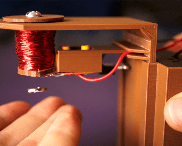
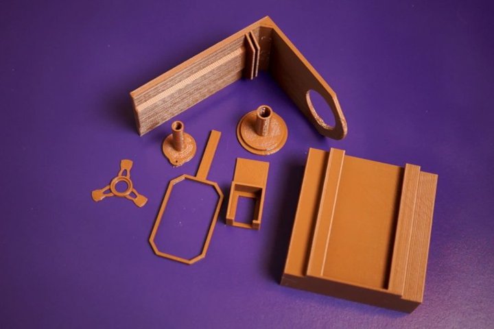


![The Predator | Official Trailer [HD] | 20th Century FOX](https://www.blogdot.tv/wp-content/uploads/2018/07/CampA_AustriaVersion_ONLINE_org.jpg)


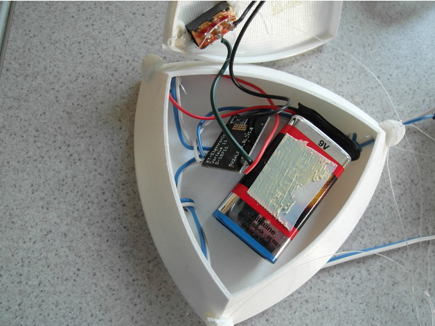


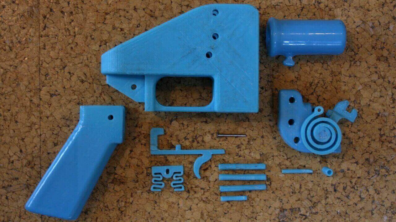

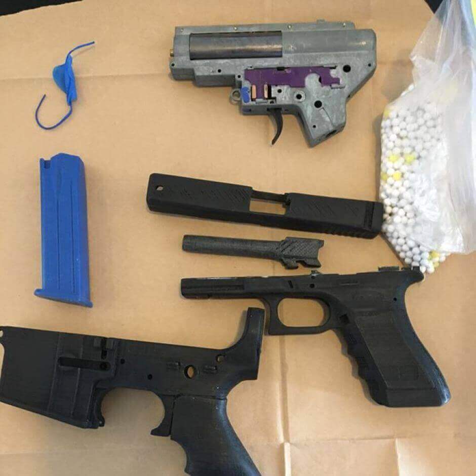


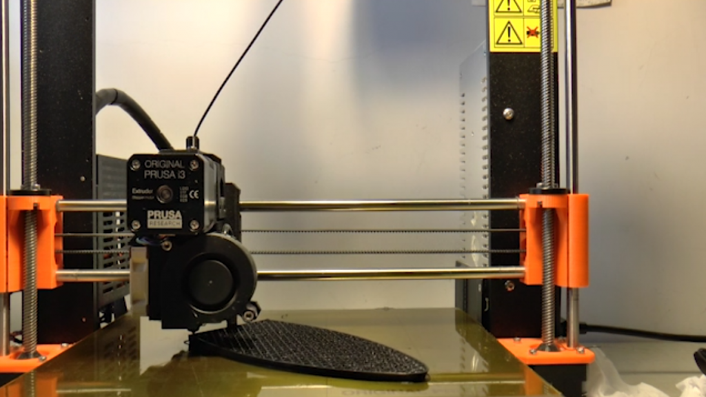

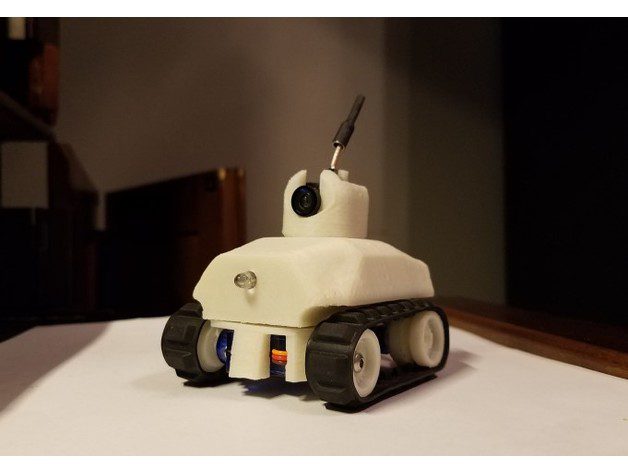


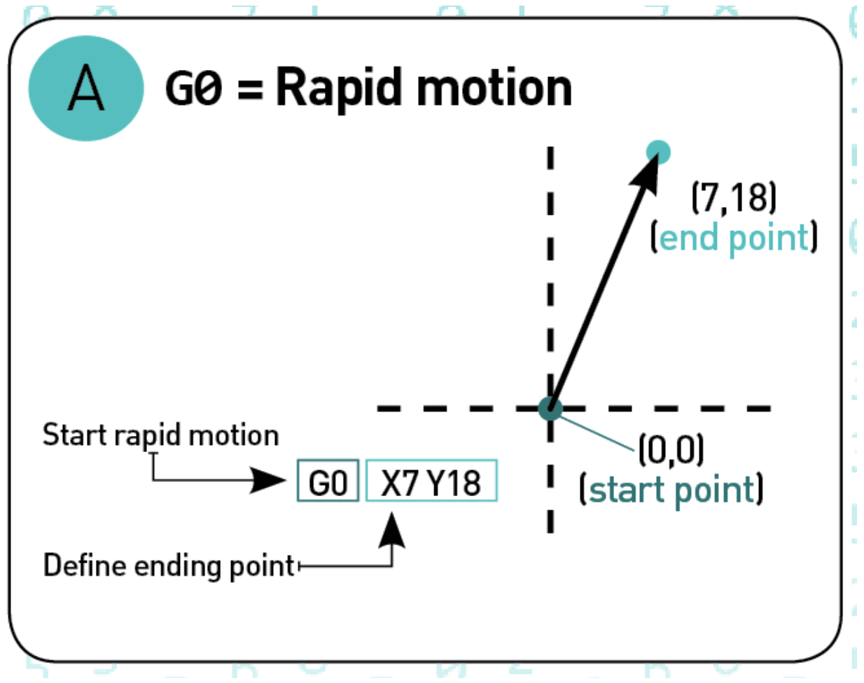

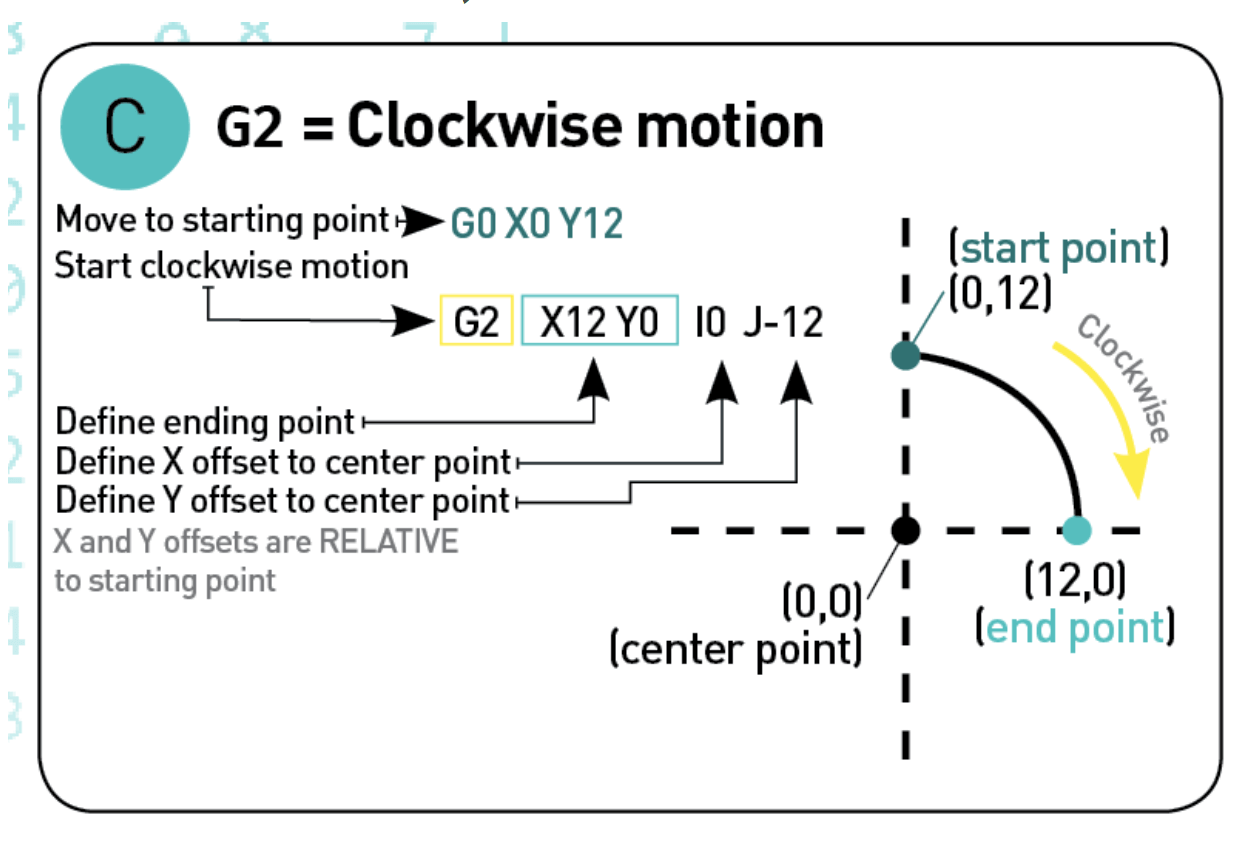


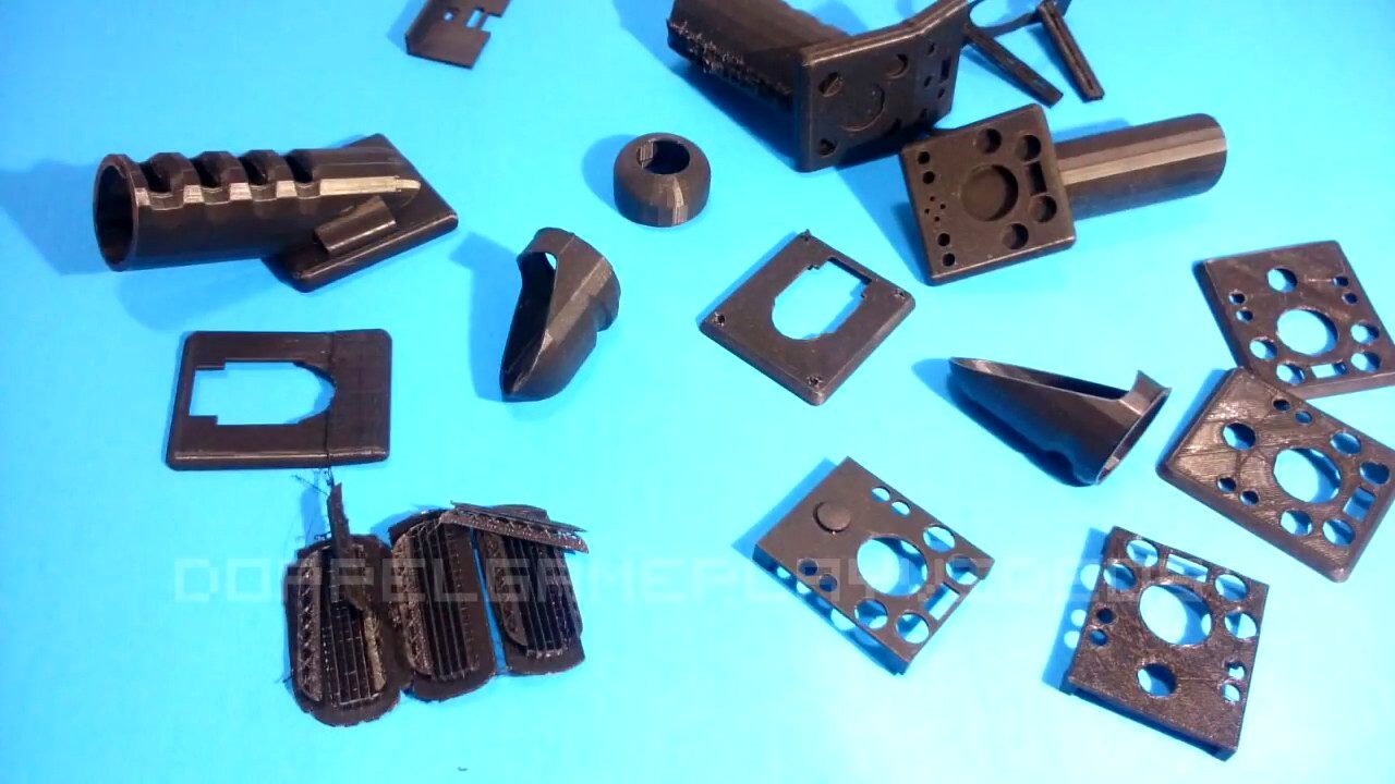
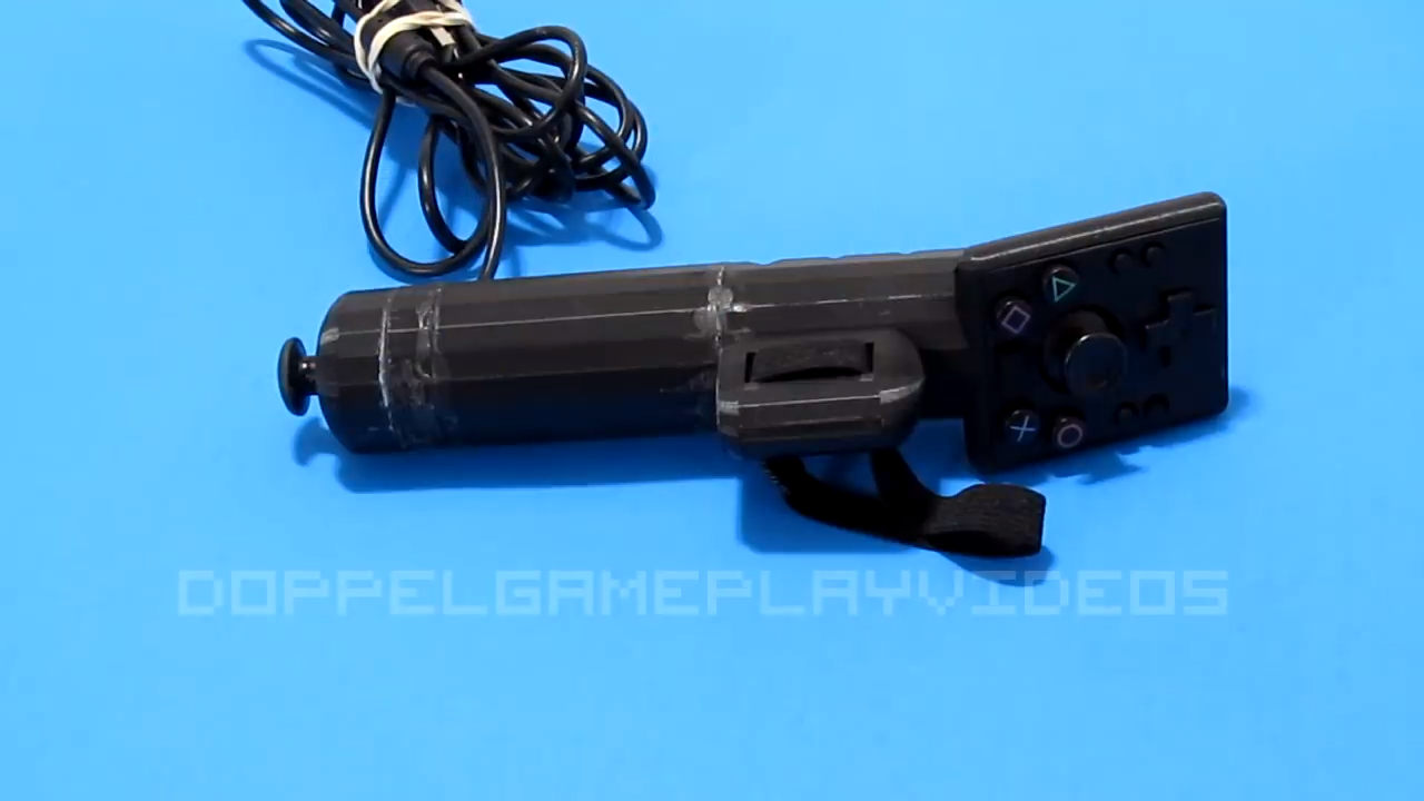
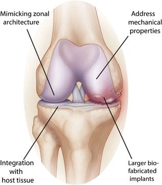

