Schlagwort: Weekend Project
-

Weekend Project: 3D Printed Motorized Turntable for Photo & Video
Reading Time: 4 minutesWant to capture all 360 degrees of an object with your camera? Adafruit has recently shared a 3D printing project that shows you how to create an inexpensive turntable made for photographers and videographers. As anyone in the photography or film world knows, the many different types of production equipment that are…
-

Weekend Project: 3D Print Your Own Workshop-Ready Steampunk Goggles
Reading Time: 3 minutesMany steampunk cosplay items provide mechanical style and an aesthetic look. But these elaborate 3D printed steampunk goggles are equipped with prescription lenses and welding filters that will keep your eyes safe while you’re in the workshop. Inspired by historical science fiction and steam-powered machinery, the steampunk genre has blossomed into one…
-

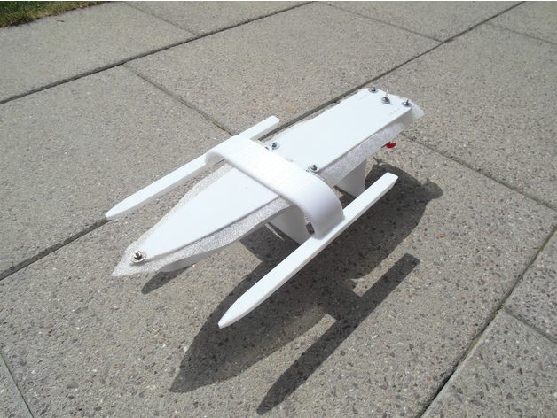
Project of the Week: 3D Print a Solar-Powered Open RC Boat
Reading Time: 3 minutesWant to spend the summer days sailing the seven seas and soaking up the sun? Thingiverse user UniversalMaker shows us how to build a 3D printed Open RC Boat equipped with solar panels. With summertime approaching and warm weather abound, it’s the perfect time to head over to your local body of…
-
Weekend Project: Create a 3D Printed Pocket Microscope from E-Waste
Reading Time: 4 minutesHave an ancient DVD or CD drive collecting dust in your garage? You can use your 3D printer and a recycled lens to create an e-waste pocket microscope. For those of us living in the modern world, it’s hard to imagine surviving without the electronics that have become such an integral part…
-

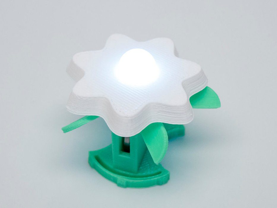
Weekend Project: Make Your Garden Glow with 3D Printed LED Flowers
Reading Time: 4 minutesWant to give your 3D printer the green thumb? Autodesk and Instructables content creator Becky Stern shares a project on how to make 3D printed light-up flowers with LED lights. FDM desktop 3D printing has opened up a new world of possibilities when it comes to making customizable and decorative objects. By…
-

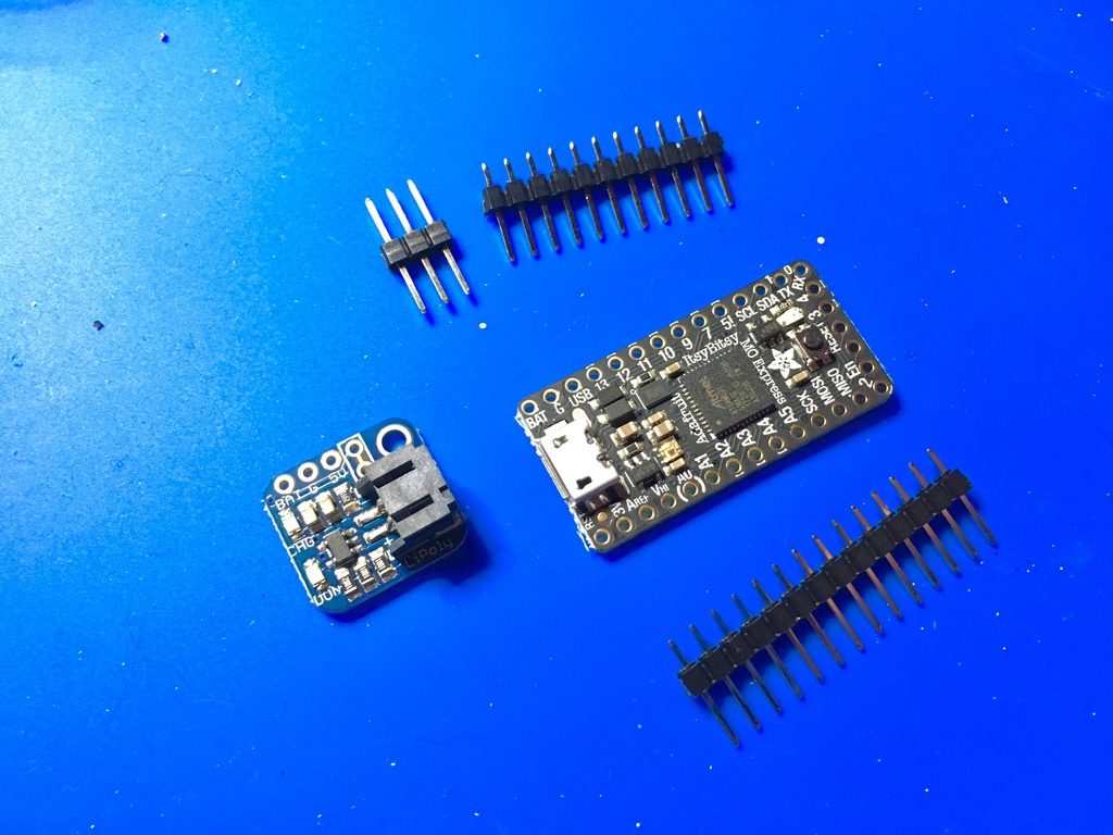
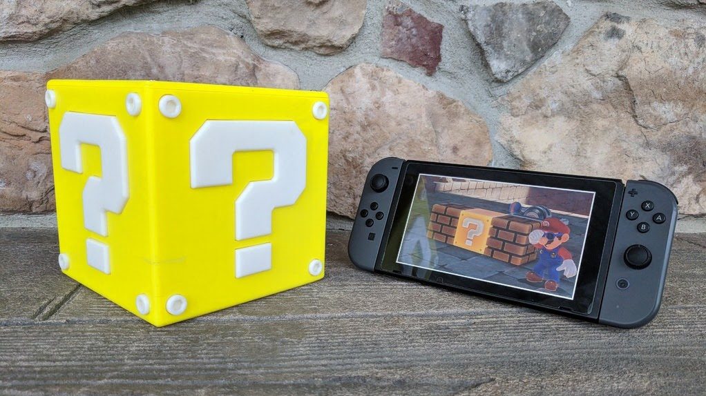
Project of the Week: Make Your Own Coin-Spitting Mario Question Block
Reading Time: 3 minutesFor this week’s Project of the Week, 3D print and Arduino your way to this coin-spitting Question Block from universe of Nintendo favorite, Mario. Loose change, shrapnel… whatever you call it, the blight of small denomination coins deserves better than sitting in a jar on the shelf at home. Which is perhaps…
-

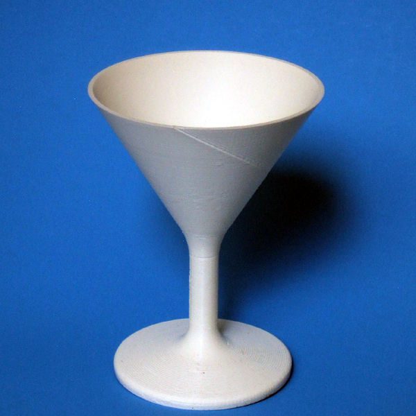
Weekend Project: How to 3D Print Watertight and Airtight Containers
Reading Time: 3 minutesA new Instructables post from user mikey77 shows how you can adjust your 3D printing slicer settings to make watertight and airtight containers, cups, tanks, and more. There are tons of useful and unique objects that you can create with your desktop 3D printer, but there are certain factors that prevent makers from…
-

Weekend Project: Take Aim With This Awesome 3D Printed Mini Crossbow
Reading Time: 3 minutesSouth Korean maker “DIYPark” shows us how to create a fully 3D printed and functional Mini Crossbow. Set up some targets and take aim, because it’s time to get your archery on. When taking on a DIY project, we often see how combining 3D printing with electronics and other technologies can produce…
-

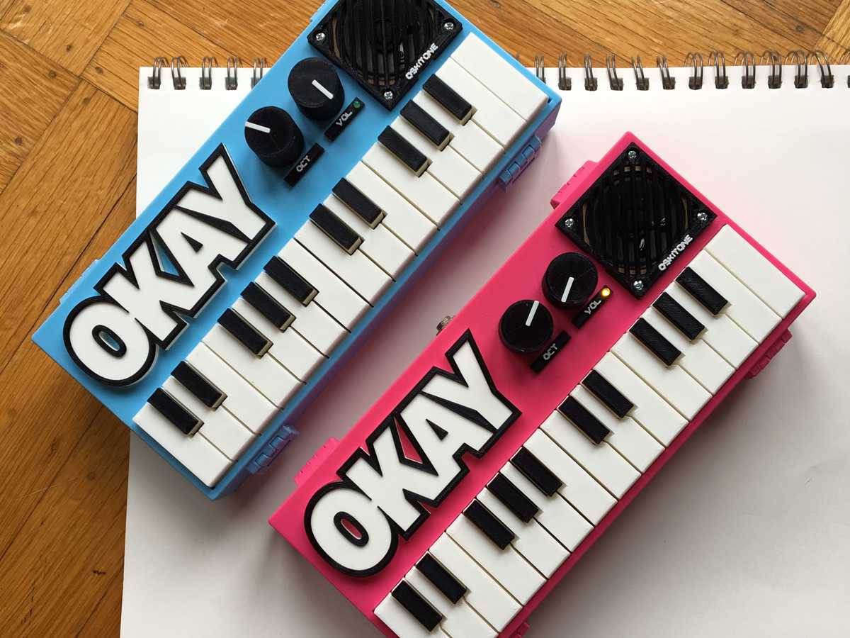
Weekend Project: 3D Printed OKAY 2 Synth Brings Music to the Maker’s Ears
Reading Time: 3 minutesOskitone’s new and improved OKAY 2 is a mind-blowing DIY synth that you can 3D print and put together on your own. Hone your 3D printing and soldering skills with this sweet musical instrument and let the sounds sweep you away! Looking for a new musical instrument to play? Why not use…
-

Weekend Project: 3D Print Your Own Customizable Soda Can Lamp
Reading Time: 3 minutesAn engineer named Arnd (also known as AHNT) recently shared a fun 3D printing project, showing us how to create an customizable soda can lamp that can you light up with LEDs or a candle. Here at All3DP, we go through a lot of 3D printing filament and thirst-quenching carbonated drinks, so…
-

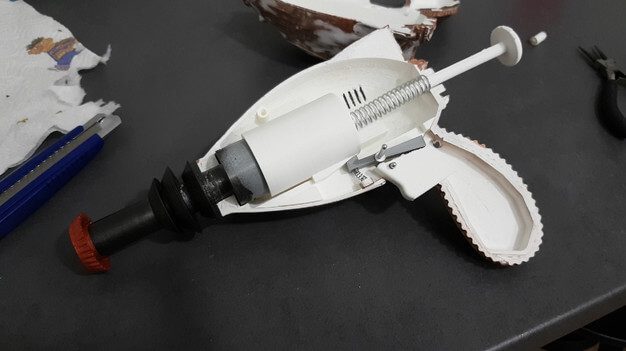
Weekend Project: 3D Print Your Own NERF Thirst Zapper Gun From Fallout 4
Reading Time: 3 minutesWith just a spring and a 3D printer, Croatian digital artist and maker Vedran Marjanovic Wekster shows you how to create a NERF-ified version of the Thirst Zapper gun from the video game series Fallout. In the post-apocalyptic setting of the critically acclaimed video game Fallout 4, the main character– referred to as “Sole…
-
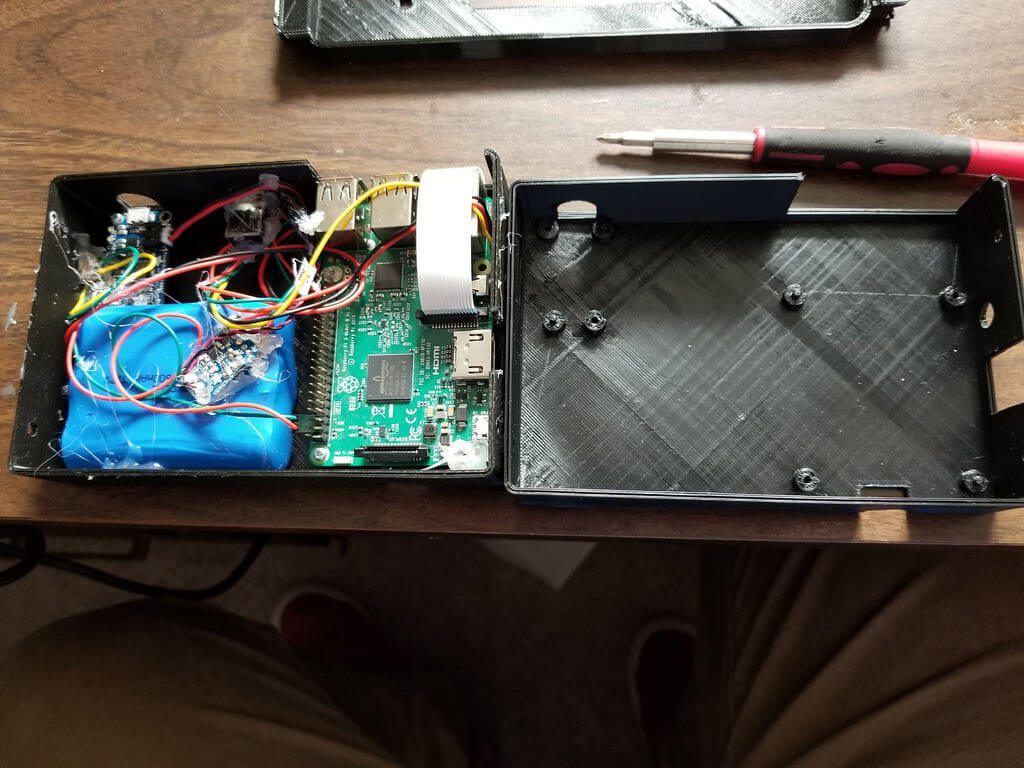
Weekend Project: 3D Print Your Own RetroPie Nintendo Switch
Reading Time: 4 minutesThe Nintendo Switch games console is an undeniable success. But, retailing for a few hundred dollars, its does require a significant chunk of change. Why not build your own for a fraction of the cost instead? Here’s how (disclaimer: the PiSwitch will not play Nintendo Switch games). Home hackable gaming has never…
-

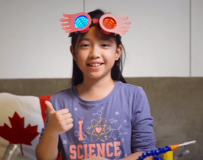
Weekend Project: 3D Printed Harry Potter Spectrespecs with LED Lights
Reading Time: 4 minutesEight-year-old maker Purple Oranji turns Adafruit NeoPixel goggles into a pair of 3D printed Spectrespecs, the zany light-up shades featured in the Harry Potter movies. This weekend project is the perfect way to show your kids that a 3D printer is just as extraordinary as a magic wand. When author J.K. Rowling…
-

Weekend Project: A $20 DIY Heated DryBox for 3D Printing Filament Storage
Reading Time: 3 minutesWant to keep your filament in tip-top shape? Engineer and 3D printing enthusiast RichRap shows us how to create DIY Heated DryBox for 3D Printing filament for under $20. No matter how finely tuned your 3D printer is, the quality of your prints are highly dependent on the state of the filament you’re…
-

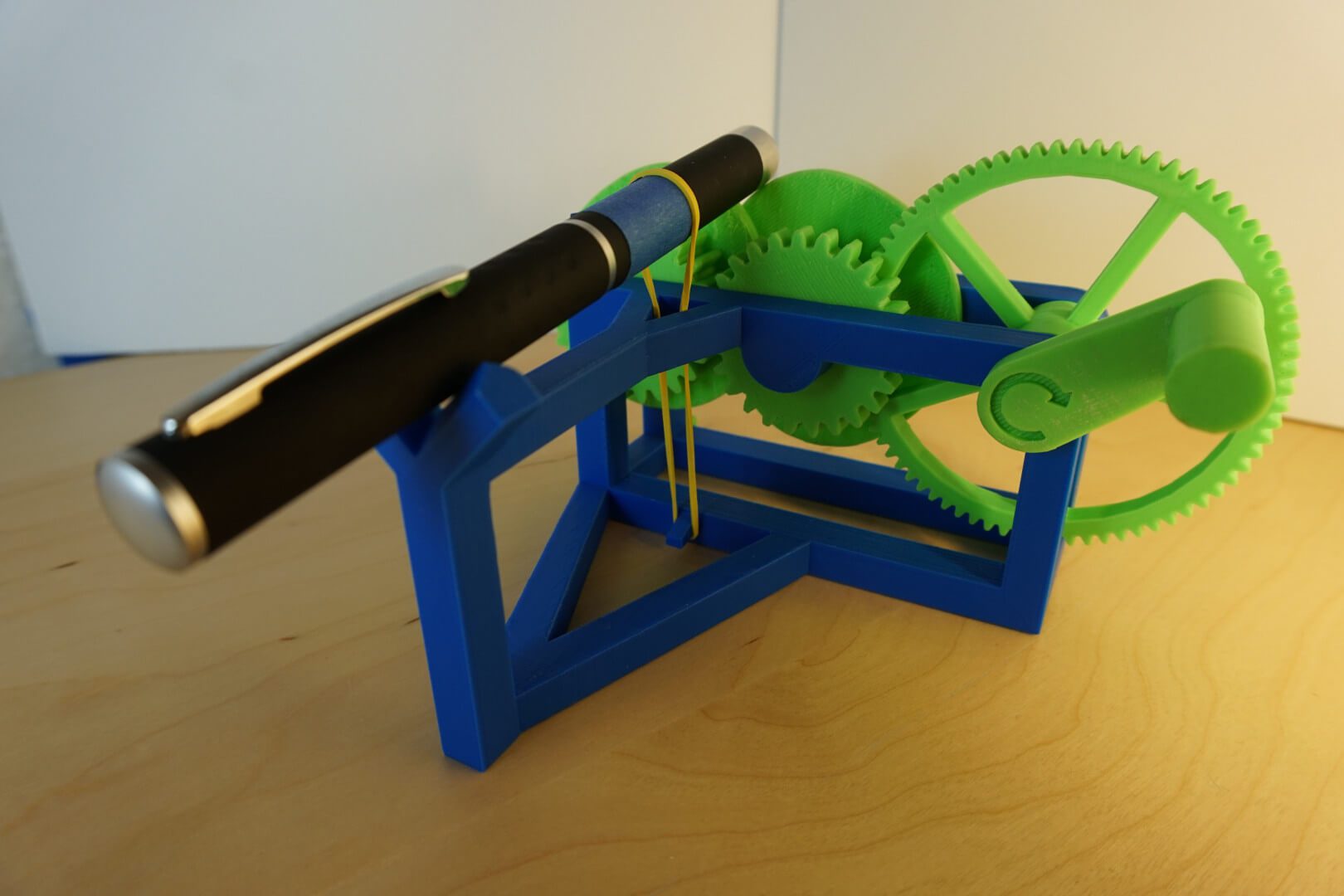
Weekend Project: 3D Print Your Own Mechanical Laser Show!
Reading Time: 3 minutesLooking for a weekend DIY project? Check out this awesome 3D printed hand-powered mechanical laser show created by software developer Evan Stanford. Is your 3D printer sitting idle this weekend? Want to find a amusing project to show your friends and family just what this technology is capable of? What better way…