Kategorie: Reviews

  • Review: Learn LibreOffice with Raspberry Pi

    Review: Learn LibreOffice with Raspberry Pi

    Reading Time: 3 minutes

    LibreOffice Getting Started Guide

    You don’t need to pay big bucks or for a regular subscription to access high-quality office software. Available on all major platforms, LibreOffice is a fully fledged office suite that includes apps for word processing (Writer), spreadsheets (Calc), presentations (Impress), vector graphics editing (Draw), mathematical formulae (Math), and databases (Base). The whole suite is included in the full version of Raspberry Pi OS, so you can get straight to work on your new Raspberry Pi 400 (or any other model).

    Although the main office programs will feel fairly familiar to many users, this official guidebook (also available as a free PDF download) from the makers explores the suite in detail to help you get the most out of it. A setup chapter goes through various general settings, before the book shows how to create and apply styles and templates (a key feature of LibreOffice) to help speed up document formatting. Subsequent chapters take you through each individual office app, followed by guides to printing, images, HTML files, macros, and customisation.

    Creator: The Document Foundation

    Price: $11

    URL: magpi.cc/librebooks

    Getting Started Book

    LibreOffice Help

    Clicking the Help option within LibreOffice takes you to this comprehensive online resource that should help you solve most issues. Every aspect of the suite is covered in detail and it’s easy enough to navigate. As well as a drop-down list of modules (apps) and a search facility, there’s an index list of keywords for all LibreOffice modules: click on a keyword to open the linked Help page.

    In addition, there’s a handy section for Common Help Topics, such as configuration, version tracking, printing, charts/diagrams, working with PDFs, and automatic functions. A particularly useful topic in this section covers compatibility with documents in Microsoft Office formats – they can all be imported without issue, although some special features may not work in exactly the same way.

    Creator: The Document Foundation

    Price: Free

    URL: magpi.cc/librehelp

    LibreOffice Help

    Udemy LibreOffice courses

    There’s no end of online courses available to learn LibreOffice, at a wide range of prices – you can pay hundreds for some. Udemy’s courses start at a reasonable £19.99 – at the time of writing, many were available at £9.99, so it’s worth looking out for special offers.

    Most of the courses cover a single app and all comprise a series of short video lectures, so it’s bite-size learning that you can dip in and out of easily when you have time. There are also assignments or exercises to complete and example files on which to practise your new-found skills. Complete the course and you’ll receive a certificate, although it can’t be used for formal accreditation.

    Creator: Udemy

    Price: From £19.99

    URL: magpi.cc/libreudemy

    Udemy LibreOffice courses

  • Korg Monotron MIDI

    Korg Monotron MIDI

    Reading Time: 3 minutes

    Recognising that, musician and engineer Zack Scholl got to work on a solution, using a Raspberry Pi to add MIDI functionality. The end result is music to our ears since it not only makes the synthesizer infinitely more playable but has allowed Zack to record an entire music album.

    “The ribbon controller made it near-impossible to play multiple notes in tune because moving your finger just a few millimetres changes the pitch,” Zack explains. “That’s where adding MIDI functionality comes it handy.” Indeed, it means a wide variety of electronic musical instruments and computers can now be added. “The easiest modification is to get a keyboard that speaks MIDI and convert the MIDI notes into voltages that the Korg Monotron understands,” Zack says.

    Tuning in

    A Python script cycles through voltages for 30 seconds to get the Korg Monotron in tune, then a mini keyboard can be attached

    By choosing a Raspberry Pi for the project, Zack was able to avoid the pitfalls of similar mods which tend to require lots of components and PCBs. “The biggest drawback of other projects is that they have had no way of automatically tuning the Monotron – that is, they can’t determine exactly which voltage corresponds to which frequency on the unit,” he says.

    Zack’s approach provided the ideal solution and it means he can play the Monotron with itself and other instruments. “Raspberry Pi can easily understand MIDI via USB and the MIDI input can be converted to a voltage using a DAC [Digital to Analogue Converter] plugged directly into the external pins,” he says.

    Indeed, the build was relatively straightforward. “The biggest challenge has been to keep the Monotron in tune. The cheapness of the synthesizer means it doesn’t have any circuits to keep the pitch locked into a certain scale or tuning, but by routing the audio from the Korg Monotron into the recording input of the USB audio device, Raspberry Pi is able to ‚learn‘ which voltage corresponds to which frequency.”

    A star is born

    Just two connections need to be soldered on the back of the well-labelled Korg Monotron PCB: one to the gate pad and the other to the GND pad

    To achieve this, Zack wrote a custom Python script that could adjust the voltage and frequency, making use of two modes – tune and play – with the former sending out voltages and listening to the USB audio input to calculate the voltage-frequency relationship. “When you put it into play mode it will listen to MIDI and use the calculated voltage-frequency relationship to figure out which voltages to send out to the Korg Monotron, which changes its pitch according to the incoming voltage,” he reveals.

    It’s also possible to play the Korg Monotron without a keyboard at all. A text file can be run instead and Zack wrote the program to do this before he even created the Monotron project. “The software lets me connect to Raspberry Pi via a Secure Shell and directly write notes into a file that will be played by the Korg Monotron,” he explains.

    “This was great because it turned Raspberry Pi into a self-contained musical instrument. Essentially you can just connect it to the synthesizer and it will play whatever you want. It frees up my hands to modulate the effects and it makes for some really impressive-sounding music.“

  • Use a retro DB9 joystick with Raspberry Pi 400

    Use a retro DB9 joystick with Raspberry Pi 400

    Reading Time: 6 minutes

    Step 01: Install the Free Unix Spectrum Emulator

    Also available in the RetroPie emulation distro we’ve used in previous tutorials, the FUSE ZX Spectrum emulator can be found in Raspberry Pi OS’s standard repositories, so installation is a bare minimum of fuss. Open a Terminal window and type:

    sudo apt install fuse-emulator* spectrum-roms opense-basic libspectrum8

    This will install FUSE, its GTK and SDL frontends, and both open-source system ROMs and the original Spectrum system ROMs. Permission has been granted for free modification and distribution of the latter.

    While the open-source ROM can only handle a limited selection of files, that spectrum-roms package will allow you to play a wide array of games, including the latest generation of technically spectacular releases for the platform.

    Step 02: Test FUSE

    Next, we’ll make sure FUSE is working with the ZX Spectrum port of Locomalito’s open-source classic, L’Abbaye Des Morts. In a Terminal, type:

    wget https://spectrumcomputing.co.uk/zxdb/sinclair/entries/0030109/AbbayeDesMorts.tzx.zip
    fuse-sdl

    Press F2 to open FUSE’s file browser, navigate to AbbayeDesMorts.tzx.zip, and press ENTER. The game should load and run automatically. For full-screen mode, press F1, go to Options, and select ‘Full screen’. Take note of the Filter option in the same menu, which lets you choose the emulator’s upscaling method: ‘TV 3x’ gives you some pleasing scan lines and the correct aspect ratio.

    „Wiring up the DP9 port to Raspberry Pi’s GPIO is a fairly simple process“

    Step 03: Wire up your joystick port

    Standard DB9 connectors split the nine pins of your cable into nine screw-down terminals. We found it most convenient to use male-to-female jumper cables for this, clamping the male tips into our DB9 breakout connector.

    For a classic single-button joystick like the Competition Pro Retro we used, pin 1 is up, pin 2 is down, pin 3 is left, pin 4 is right, and pin 6 is fire. Pin 8 connects to ground – we recommend using a green cable for it. Some joysticks may require you to connect port 7 to a 3.3V power connector on the GPIO, but the Competition Pro does not.

    See the ‘DB9 pins’ box for an at-a-glance DB9 connection table.

    Step 04: Wire up Raspberry Pi

    Figure 1 GPIO connection points for two singlebutton joysticks, corresponding to the ‘GPIO connections’ table (below). Joystick 1 is purple, joystick 2 is orange. Use your choice of ground pins for each controller: ground pins 6 and 14 are marked in green here

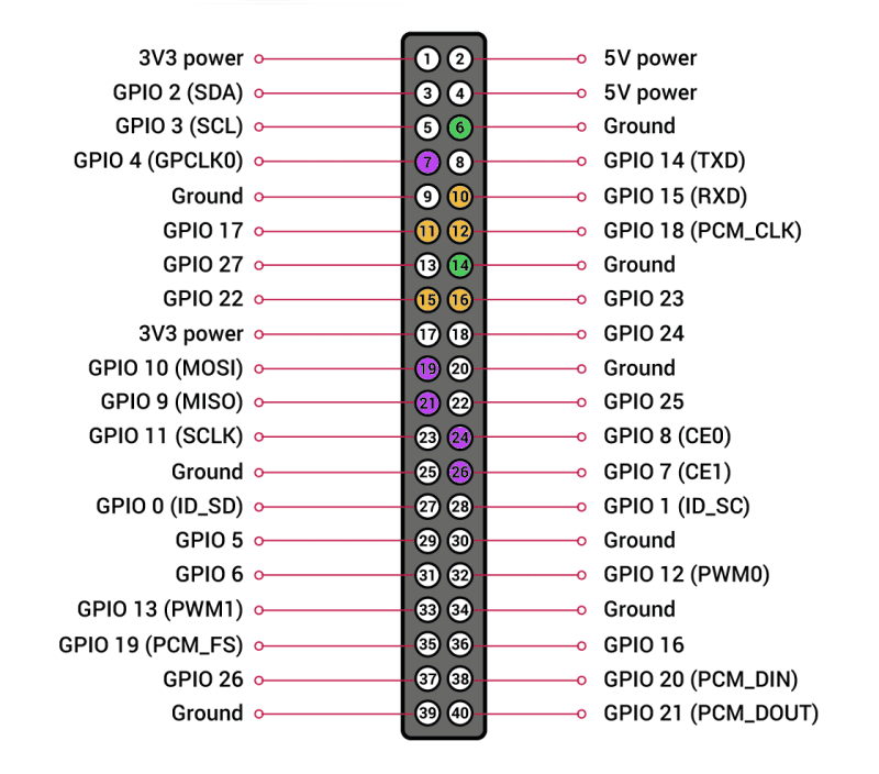
    Wiring up the DP9 port to Raspberry Pi’s GPIO is a fairly simple process, although you’ll have to do some careful pin counting. On Raspberry Pi 400, pin 1 is at the top right of the horizontally oriented GPIO port and pin 40 is at the bottom left. Remember that GPIO numbers don’t correspond with pin position numbers.

    For a reminder of where everything is, open a Terminal and type:

    pinout

    .

    Our GPIO Connection diagram (Figure 01) shows where the female jumpers connected to your DB9 port need to go on Raspberry Pi. For a single one-button joystick, up goes to GPIO 4, down to GPIO 7, left to GPIO 8, right to GPIO 9, and fire to GPIO 10.

    Step 05: Build the DB9 joystick driver

    Let’s build the driver. Enter this in a Terminal window: 

    sudo apt install dkms raspberrypi-kernel-headers
    git clone https://github.com/marqs85/db9_gpio_rpi.git
    cd db9_gpio_rpi
    sudo cp -r db9_gpio_rpi-1.2 /usr/src/db9_gpio_rpi-1.2/
    sudo dkms add db9_gpio_rpi/1.2
    sudo dkms build db9_gpio_rpi/1.2
    sudo dkms mkdeb db9_gpio_rpi/1.2 --source-only
    sudo modprobe --first-time db9_gpio_rpi map=1,1

    That

    map

    option defines what kind of joystick you’re using, with each number classifying a different type of joystick As we’re using a one-button joystick,

    map=1,0

    would do it, but

    1,1

    means we can connect a second stick of the same type to a second port.

    Step 06: Test your joystick

    Building and loading the driver won’t quite get us to a functional joystick, as the driver isn’t fully compatible with Raspberry Pi OS’s recent use of raspi-gpio instead of gpio. However, this is a great time to test your joystick to make sure that it’s wired up correctly

    sudo apt install jstest-gtk
    jstest-gtk

    You should see your joystick in the peripherals list. When you click into it, if you’re using a Competition Pro Retro or similar joystick, you’re likely to find that the fire button is jammed on and that the horizontal x axis is stuck at the left.

    „Although many Spectrum games support joysticks, you’ll often have to enable support for these“

    Step 07: Pull-ups are good for you

    This is because your GPIO needs to be set up to handle the joystick’s pull-up switches. On a standard DB9 GPIO configuration, this script will do this for you. Create it using your preferred text editor and save it somewhere handy. We’ve put ours in /home/pi/pullup.sh.

    Test it by running:

    sh /home/pi/pullup.sh
    jstest-gtk

    If the joystick is now aligned properly and the button isn’t stuck on, you’re in business.

    chmod +x /home/pi/pullup.sh

    Finally, let’s load those pull-up settings on boot.

    sudo mousepad /etc/rc.local

    Above the

    exit

    line, enter the following:

    /home/pi/pullup.sh

    You can also place the pull-up code directly in rc.local if you wish.

    Step 08: Load on boot

    Once you’re satisfied that your joysticks work, you’ll want to load the driver module on boot.

    sudo mousepad /etc/modules

    …and add:

    db9_gpio_rpi

    After saving and exiting the file, enter:

    sudo mousepad /etc/modprobe.d/db9.conf

    This file should contain the following line:

    options db9_gpio_rpi map=1,1

    If you’re using a different joystick and configuration, you’ll need an appropriate map, and possibly some extra GPIO connections, which you can find here.

    Reboot Raspberry Pi and use

    jstest-gtk

    to ensure that everything is working as it should. You can now use the driver as a generic controller input device.

    Step 09: FUSED joysticks

    The jstest-gui program allows you to test your joystick and also indicates whether it’s working as it’s supposed to

    FUSE doesn’t enable joystick support by default, so we’ll have to set that up. Run

    fuse-sdk

    , then press F1 for the menu. Go to Options > Peripherals > General. Press SPACE to enable Kempston joystick support, then press ENTER.

    Press F1, then Navigate to Options > Peripherals > Joysticks and make sure both Joystick 1 and Joystick 2 are set to Kempston. If not, press ENTER, press ENTER again to open the Joystick type options, navigate to Kempston on the list, and press ENTER again.

    Note that some games may default to using Joystick 2, so you’ll want to configure both, even if you only have a single stick connected.

    When you’re happy with your settings, open the Options menu, and select Save.

    Step 10: Game configuration

    Although many Spectrum games support joysticks, you’ll often have to enable support for these. L’Abbaye des Morts enables joystick support by default, but its menus provide a good example of what to look for.

    Load the game and then press C on the keyboard to access the control configuration. Pressing 1 here enables and disables Kempston joystick support. In other titles, you may need to explicitly choose to use your joystick to control the game if you want it to work.

    Step 11: Get game

    The Spectrum’s been a long-time home-brew favourite, with software continuing to come out for years past its original availability. There’s been a resurgence in popularity of the platform with the release of a number of successors, most recently the ZX Spectrum Next.

    As ever, the indie-friendly itch.io digital distribution platform is one of the best places to find both free and commercial releases for the Spectrum, and we’ve put together a list.

    Step 12: Boot to black

    Finally, let’s start

    FUSE

    on boot for that authentic Spectrum ambience. In /home/pi/.config/autostart create a text file called fuse.desktop. If the directory doesn’t exist, create it. Add the following lines to your new tile:

    [Desktop Entry]
    Type=Application
    Name=FUSE
    Exec=/usr/bin/fuse-sdl --full-screen

    You can exit

    FUSE

    at any point to return to Raspberry Pi OS’s familiar Pixel desktop.
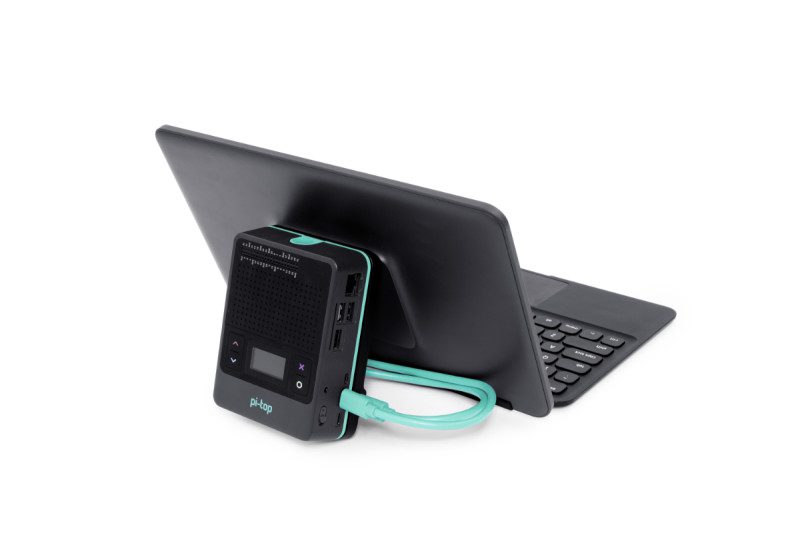
  • FHD Touch Display & Bluetooth Keyboard review

    FHD Touch Display & Bluetooth Keyboard review

    Reading Time: 3 minutes

    The two parts are sold separately, but designed to work together. The result resembles a Raspberry Pi-based Microsoft Surface laptop. To the rear is an adjustable kickstand, which the pi-top [4] case clicks onto. An 80cm display cable connects the two elements. The length ensures you can disconnect the pi-top [4] and have it sitting to one side.

    Weighing it up

    Altogether, the keyboard, screen, pi-top [4] DIY Edition, and display cable weigh in at 1620g. Not spritely for a tablet computer, but light enough for us to throw in a backpack and take to the coffee shop. It was stylish enough to use without raising any eyebrows.

    There’s an elephant in the room that we should address. Together, the FHD Touch Screen and Bluetooth Keyboard will set you back £242. This is on top of £95 for the pi-top [4] DIY Edition case. And you will need to supply your own Raspberry Pi 4 (from £35, or £54 for the 4GB model tested here). So you are looking at around £370-£400 for this setup.

    With that elephant firmly kicked out of the room (for now) we are pleased to report that everything we tested was fantastic.

    FHD Touch Display

    The pi-top [4] DIY Edition clips to the kickstand for a neat all-in-one solution

    First up is the 11.6-inch touchscreen display with a resolution of 1920×1080 at 190ppi (pixels per inch). It’s a great display, although the chunky bezels are a tad retro.

    It is a ten-point capacitive touchscreen and we found it highly responsive. While there is no multi-touch interface support in either pi-top OS or Raspberry Pi OS, it’s very useful to tap buttons and interface elements.

    Bluetooth Keyboard

     A stand-out for us was the touchpad which was snappy and responsive, and deflected accidental touches. A first for a Raspberry Pi laptop

    The Bluetooth Keyboard clips to the base of the screen (again, magnetically) via a connector. There is no need to pair the keyboard. However, set up Bluetooth and you can disconnect the keyboard and use it to one side. We found it an absolute joy to type this review out on it.

    Along the function keys sit a selection of shortcuts, including a dedicated Terminal key that we quickly fell in love with.

    Below the keys is a multi-touch trackpad and, by Jove, they have cracked it. There is no accidental thumb touching, no awkward cursor jumping, and you can left- and right-click with ease. This is the only time we have encountered a Raspberry Pi laptop with a fully decent touchpad.

    pi-top OS

    We spent a couple of hours in Costa writing this review. With pi-top [4], Raspberry Pi comes together into one neat package that’s a delight to work on. All that really leaves is the price, and once again the elephant shows its snout.

    It is a big step up from using a Raspberry Pi with a repurposed keyboard, mouse, and monitor. On the other hand, it is considerably cheaper than a Microsoft Surface. And Raspberry Pi is a much more fun and useful computer.

    Verdict

    9/10

    This setup is packed with clever ideas and we love the keyboard, touchpad, and Raspberry Pi integration. Hands-down the best way to use Raspberry Pi on-the-go.

  • Multi-effects Guitar Pedal

    Multi-effects Guitar Pedal

    Reading Time: 3 minutes

    After buying some commercial guitar pedals, Raphaël noted that they’re normally run in series, but wondered what would happen if they could be run in parallel. “It makes a pretty big difference,” he tells us. “Suppose you have two distortion pedals: if you run them in series, you’ll hear the cumulated effect of both, while if you provide your ‘dry’ (unmodified) signal to each pedal separately and add up their outputs, you’ll then preserve the specifics of each and create a sound impossible to create when running the pedals in series.”

    Unlike off-the-shelf multi-effects units which run their effects in series internally (apply Octaver, then Fuzz, then Delay, for instance), the DIY guitar pedal he built is able to digitally create a complex parallel signal chain: “Something like the modular synth version of guitar pedals.”

    Connecting effects

    The second version of the project has a large enough case to accommodate all the electronics, including a Raspberry Pi and audio interface

    With a Raspberry Pi 3 and all the other components crammed into a handmade wooden case, the unit features six jacks (two in, two out, two expression pedal), a USB ports, three push-buttons, and a rotary encoder to control effects.

    A touchscreen interface (made using the SFML software library) enables the user to create and link multiple nodes for different effects to combine them. There’s also a live board view where you can adjust their parameters of each effect to get exactly the sound you want.

    “The centrepiece is what I call the ‘audio pipeline’,” he says. “It’s moving the audio from node to node (essentially a DFS graph traversal); visually, a node is one brick in the GUI.

    At the moment, I’ve made about 25 individual effects (bricks), each having from two to five input and output slots; you can pretty much add as many bricks as you want and connect them however you want [for] a lot of potential effects.

    “My goal is to provide enough building blocks to recreate the effects of any off-the-shelf pedal, and more, by combining filters, modulation, delays, etc.”

    We can rebuild it

    Raphaël is a 24-year-old software engineer. This is Raphaël’s first ever Raspberry Pi project.

    The project took Raphaël around half his time over a four-month period. While the software aspect was in his comfort zone, “the real hard part for me was cutting wood and soldering things. Seriously, before this project, hardware was pretty much magic to me, and wood wasn’t even a thing!”

    His reasoning for using a Raspberry Pi in the build was simple: „I want to make a pedal. I’ve got a tiny computer and a USB audio card. If I put them both in a box, that’s a pedal, right?“

    For the first version of the pedal, as used in his YouTube demo, he reveals that the wooden enclosure was too small: “There’s a 5mm gap; that’s why I shot the video from a 90° angle.”

    He has subsequently built a brand new version with a bigger enclosure, which allowed him to add an Ethernet port, another USB, and finally close the box.

    “Also, I used another audio interface, which is better suited as it can be torn apart, resoldered, and screwed directly to the enclosure; clearly better than a USB dongle flying around with bulky audio jacks connected to it.”

    Quite a few people have told him they’d love to buy his pedal, as a product or as a kit, which he is considering. “One way or another, I plan on making everything open-source relatively soon; I’d love to see people building their own effects!”

  • Car Head Unit

    Car Head Unit

    Reading Time: 2 minutes

    “My eyes lack depth perception, so I really wanted a backup camera for safety,” he explains. Off-the-shelf options were expensive, so he decided to put his engineering skills to the test. The parts ended up costing him “a fraction” of a readymade product.

    Powering ahead

    Originally, he wanted a backup camera and a large screen to display the camera view, much like the home security setup he’d created previously to keep an eye on his house while he was on holiday. He chose a Raspberry Pi 4 as the basis since he knew that model well and it offers good camera support. “The low cost was a major advantage, as well as being able to replace my plain old radio with a big, beautiful 7-inch touchscreen,” he says. 

    Levi then discovered a company called Blue Wave, which makes open-source head unit software for Raspberry Pi called OpenAuto. “I flashed my Raspberry Pi with their OS. [This provided] a graphical interface and a full suite of apps and other features you would commonly find in many stock infotainment systems, including Android Auto,” he says.

    A voltage divider and signal wire to the reverse lamp circuit in the rear light connect to a GPIO pin on Raspberry Pi. The reversing camera is summoned whenever the car is put into reverse

    Powering it was to prove a challenge as the 12V connections in his car didn’t match that of Raspberry Pi. He used a 12 to 5 volt buck converter to step-down the power supply to Raspberry Pi, though on the first attempt he got his wires mixed up, destroying his Raspberry Pi. To prevent the microSD card corrupting when the power was switched off, Levi cleverly tapped into the ignition wire behind the car dashboard then soldered a PC817 opto-coupler between it and Raspberry Pi.

    “I used a Python script I found online that told Raspberry Pi to look for a falling edge on the opto-coupler,” he reveals. “When you turn off the ignition, the opto-coupler instructs Raspberry Pi to run a shutdown script, ensuring a safe power-off.”

    Looking back

    Levi replaced the car stereo with a Quick FACTS Raspberry Pi 4, a camera to monitor what’s happening behind him, and a 7-inch touchscreen display. He designed and 3D-printed the bezel

    For others wanting to tackle such a project, Levi warns that the electrical work involved is quite challenging. “You’re splicing into electrical harnesses in your car, building voltage dividers, and doing a lot of stuff to your car that wasn’t meant to be done, so you have to be careful and know what you’re doing so you don’t damage things.”

    But it’s fair to say he’s pleased with how his project turned out: “Nothing makes an old car feel like new like a giant touchscreen in the dash,” he beams.

  • Embedded Learner Board review

    Embedded Learner Board review

    Reading Time: 2 minutes

    The Embedded Learner Board (£19 / $26) takes it a step further, though. Also, it’s not a HAT, which allows it to be a bit platform agnostic – it works with Arduino boards as well. The board itself contains a ton of different components: a 16×2 LCD display, a 7-segment display, buttons, LEDs, thermistor, IR sensor, a buzzer, even a light sensor. It packs a lot of functionality and because of that, it’s also larger than a Raspberry Pi.

    Learn to connect

    Everything on the board is well-labelled

    As it’s not a HAT, you’ll need to manually connect wires to specific GPIO pins for what you’d like to use/control. Each element on the board is labelled and each corresponding pin is equally well labelled so it’s not a big issue – especially with the code examples that teach you how each part works. You can then start using bits in conjunction with each other.

    It packs a lot of functionality and because of that, it’s also larger than a Raspberry Pi

    The examples are great and the board is pretty cool, although some of the parts are a bit more advanced for beginners than we’d prefer. Experienced parental supervision is required in our opinion, although it will be a fun shared activity.

    Verdict 

    9/10

    It packs a lot of functionality for quite a low price, although it may be a little fiddly for younger kids.

  • BOSEBerry Pi

    BOSEBerry Pi

    Reading Time: 3 minutes

    David has been a radio enthusiast since he was a kid, and was wrestling with a DAB radio in his kitchen with spotty reception.

    “I thought it might be time to replace this radio and started to wonder if I could build my own connected to the internet,” David explains. “I know this can easily be achieved using a smart speaker setup, but I wanted a radio that just played radio stations. In support of the United Nations sustainable development goal which aims for sustainable consumption, I decided to reuse a traditional radio and build my own system inside it.”

    On David’s search for a suitable radio housing, he came across old BOSE SoundDocks (from the days where iPod docks were all the rage) which were listed as faulty.

    “I suspected that these devices fail from the repeated insertion of the iPod into the docking connector,” David said. “But as I was not going to use that, it would seem a good option to use as the base for my project.”

    Replacing iPod

    Carefully gut your ‘faulty’ iPod dock. Retain
the ‘Vans off the wall’ sticker if you really want
a slice of 2011 remaining.

    Like a lot of upcycling projects, David went with a familiar solution: “I decided to use a Raspberry Pi Zero W for this project as it had plenty of processing power for the task and a very small physical footprint which could fit inside the case with ease.”

    He decided to use a full-on DAC to provide the audio he needed from his Raspberry Pi Zero, delivering audio quality higher than internet radio could ever deliver. After removing the internals of the BOSE system, he found a good space to mount Raspberry Pi Zero and other components using a custom cradle designed in FreeCAD. He also added a small class D amplifier and installed an adapter so he could use a 5 volt power supply.

    Out of a choice of music player and radio software for Raspberry Pi, David decided to keep it simple. “As the radio was not going to use a screen of any kind, I downloaded the latest version of Raspbian [Raspberry Pi OS] Buster Lite and installed it on an SD card,” he says. “All the installation was done through the command line. I installed the music player daemon and music player client which allowed me to check that the hardware was able to play the music stream.”

    He added remote control abilities, programmed in specific stations, and was done.

    Final touches

    A 3D rendering of an element of the build

    Well, nearly. David decided to go a few steps further with a custom fascia with an updated logo.

    “Although this front fascia was now complete, I decided to experiment with the style of it,” he tells us. “I started with an understated panel with embossed letters, but then thought the wording should be highlighted as a feature. This was achieved with some enamel paint to fill the depressions made by the letters. A test piece revealed that the enamel paint was being drawn up along the filaments of PLA printer thread by capillary action. This was solved by first sealing the whole face with a clear acrylic spray, then painting the detail, finishing with some wet and dry paper on the top surface. A final coat of acrylic spray provided the finishing touch of a gloss surface to match the rest of the speaker body. I give you the BOSEBerry Pi.”

  • Novaspirit Tech, aka Don Hui interview

    Novaspirit Tech, aka Don Hui interview

    Reading Time: 3 minutes

    Novaspirit Tech started back in 2003 as a placeholder for my Macromedia Flash web designs on GeoCities,” he recalls. “Then I relaunched the website at its own domain in 2010 to host my tutorials and projects, such as installing GPU on laptops to installing kernels on Android phones.

    In 2013 my website crashed and lost the data, so I looked towards YouTube to host my tutorials, and at the same time I discovered Raspberry Pi. That’s when it started to really define the tech in Novaspirit, putting together hundreds of projects for myself, friends and families.”

    What is your history with making?

     Water-cooling a Raspberry Pi is unnecessary, but very fun to see

    I’ve been a tinkerer since I was a kid. I would love to take things apart and try to rebuild or improve on them. That’s where my quote ‘Hack till it hertz’ originated from, which means hack it till it works. Making devices do what they were not first intended to do was my specialty and also my flaw, because I tend to break more things than I fix.

    How has Raspberry Pi helped some of your builds?

    Donald used to do a lot of hacks like this, installing GPUs into laptops

    Raspberry Pi has been a very critical part of my creations because I use it for what it’s intended for, a dev board. Most of my projects will start with a Raspberry Pi, whether building a small web server or running a garage door opener with GPIO. Every step of the way you will always need an environment that is reliable and doesn’t change too dramatically. From building the base code to GUI and interacting with GPIO, it’s always nice to start with a board like Raspberry Pi.

    What has the response been to your videos?

    Hacky makes with Raspberry Pi is Donald’s specialty

    Most of the projects I’ve done with Raspberry Pi have gotten a lot of good feedback, mostly impressed at how I managed to get things to work on Raspberry Pi. I believe I was the first to install Amazon Echo on Raspberry Pi, as well as Windows 10 on ARM on Raspberry Pi. I’ve even water-cooled a Raspberry Pi. I do have many firsts and the responses I get are great, although the water cooling one was just for jokes.

    What are some of your favourite Raspberry Pi builds?

    My favourite Raspberry Pi builds are the ones I use every day. The quad SATA Raspberry Pi NAS, USB over network with Raspberry Pi, and my most recent Raspberry Pi kvm-over-ip.

  • Raspberry Pi 400 Projects & Guides in The MagPi Magazine #101

    Raspberry Pi 400 Projects & Guides in The MagPi Magazine #101

    Reading Time: 3 minutes

    Raspberry Pi 400 Projects & Guides

    But where to start? That’s where our lead feature comes in. It’s packed with information and advice for getting the most out of your new Raspberry Pi 400 computer.

    Arts & Crafts with Raspberry Pi

    Get creative with Raspberry Pi arts & crafts projects

    Get out your sticky tape, cardboard and crafting tools with our guide to making things with an electronic angle. Discover a wide range of crafting projects that use lights, sensors, and buttons. We’ve got fashionable wearables, interactive art displays, plus badges and baubles. Everything you need to get inspired by making with Raspberry Pi. 

    Use a retro DB9 joystick with Raspberry Pi 400

    Wire up a retro joystick to Raspberry Pi 400

    We love the classic DB9 joysticks, made popular in the 1980s (like the Kempston one we use in this tutorial). Nothing beats playing retro games with an original joystick. In this tutorial you’ll learn how to use a DB9 adaptor and wire it up to the GPIO pins on a Raspberry Pi 400 computer. Then plug in your original joystick and play games in the original way.

    BOSEBerry Pi

    Upcycling an old speaker system with ultra-modern innards

    We love this BOSEBerry Pi project by David Hunt. He has taken an old BOSE SoundDock from the iPod days and upcycled it with Raspberry Pi. Now it can stream music, internet radio, and keep him updated with the latest news and events. 

    Santa's Run: Drop & Dash

    Upgrade Santa’s Run with Drop and Dash games

    Santa’s Run is a great game that uses recycled plastic bottles and arcade buttons as controllers. This month, Mike Cook explains how to use those controllers to make two more games: Santa’s Drop and Santa’s Dash.

    FHD Touch Display and Bluetooth Keyboard

    pi-top FHD Touch Screen and Bluetooth Keyboard

    Fancy turning Raspberry Pi into a Microsoft Surface-style tablet computer? With pi-top’s latest hardware you can add a touch-screen and keyboard cover to Raspberry Pi. The result is the nicest way to work on the move around.

    Pick up your copy of The MagPi magazine #101

    The MagPi magazine is available as a free digital download, or you can purchase a print edition from our Raspberry Pi Press store.

  • Win a Raspberry Pi 400!

    Win a Raspberry Pi 400!

    Reading Time: < 1 minute

    Subscribe

  • Santa’s Run

    Santa’s Run

    Reading Time: 6 minutes

    Step 01: The game

    It’s Christmas Eve, ten to midnight in 2020. The moon is waxing gibbous, at a phase of
    73%, the constellation of Orion stands as high in the sky as it gets from these latitudes,
    and Santa is about to make his overhead pass. He is propelled through the sky by a
    mixture of magic and the energetic shaking of his eager recipients – that’s you. His mission is to deliver every single copy of The MagPi magazine to the people waiting
    below. He has two passes to the end of the screen and back. Will he make it, or will
    some fall into the soggy snow?

    Step 02: The controller

    Figure 1: Photograph of Raspberry Pi computer connection

    The hardware controller we are about to build is about as simple as it gets. It consists of
    a tilt switch mounted in a plastic drinks bottle. This then connects to a GPIO pin on
    Raspberry Pi, and the rest is software. We first used tilt switches in The MagPi issue 52 with the sliders game – coincidentally also a Christmas game, and one of
    our favourites. But this time we only need one switch. We used a small (140mm) flip-top
    drinks bottle from a discount supermarket, and mounted the switch in the top.

    Step 03: Make your shaker

    We used thin screened microphone wire for the connection; it is only 1.6mm in
    diameter. This makes for a nice neat job, but any sort of wire will work. First we drilled a
    2mm hole in the flip top cover, and then threaded the wire through. Then we trimmed
    the wire on the tilt switch down to about 5mm and soldered a wire on each connector
    (Figure 1). Then we pushed the tilt switch through into the bottle until the wires were
    below the level of the rim, and flooded the top recess with hot-melt glue, ensuring the tilt
    switch was vertical, as shown in Figure 2.

    Step 04: Connecting to the GPIO pins

    Figure 2: Hot-melt glue fixing the tilt switch

    To connect the other end of the tilt switch to the GPIO pins, we used a ten-pin dual-row
    header socket. We connected the wires to pins 2 and 9 of the header socket; this
    corresponds to ground and GPIO 3, as shown in the photograph in Figure 3. We used an I2S pin because of the, already fitted, 1K8 (1.8kΩ) pull-up resistor to give it good immunity from interference. Figure 4 shows the physical layout diagram for the whole
    interface. We then ran a short test program, available on our GitHub page, to check it worked.

    Step 05: Graphics

    One of the major components of this sort of project is the graphics, so we got them
    together before starting on writing any code. We looked around the net for royalty-free
    Christmas animated GIFs of Santa’s sleigh, and found a good one with seven reindeer.
    This was too many for our needs, so we used a photo editing package to remove all but
    the first pair. We split the GIF into its separate frames and started editing: first removing
    excess reindeers, then making the background transparent, and finally adding the
    Raspberry Pi logo onto the sides of the sleigh.

    Step 06: Your first dashboard

    Figure 3: Photograph of Raspberry Pi computer connection

    Then we found a chimney and made it a double chimney with a copy and flip of the
    original clip art. We also did some retouching on the snow line between the chimneys,
    to make the transition smooth. Most importantly, we made the snow line at either side of
    the chimneys end at the same height. Finally, we made two lengths of just plane snow:
    one the same length as the chimneys, and the other half the length. In this way, we
    could mix and match the graphic elements in the scrolling ground display.

    Step 07: The MagPi covers

    This could have been hard work, going through all the back issues online and taking
    screen grabs, but fortunately the magazine was planning to put all the covers on the
    front page of the 100th issue, so they had gathered them together already. We only had
    to scale them, in our case to 50 pixels wide. The final element was the star-studded
    background for Santa to ride across, but been very keen on astronomy, we wanted this
    to be accurate, along with the position and phase of the moon. So we turned to a great
    open-source planetarium package Stellarium.

    Step 08: Stellarium

    Figure 4: Physical diagram of the who project

    Stellarium has been around for at least 15 years and is, by now, a very sophisticated
    product available free for all three major platforms. We used it to look at the sky as it
    would be on Christmas Eve 2020. While leap years keep the stars in the same place at
    a specific date from year to year, the moon’s position and phase will change. This year
    the moon is waxing gibbous, at a phase of 73%. ‘Waxing’ means it is getting fuller day
    by day, ‘gibbous’ means it’s between half and full, and &quot;phase&quot; is how much of the moon you can see.

    Step 09: Poetic licence

    We took a bit of poetic licence when it came to the size of the moon. When looking at it
    in the sky, we actually perceive it to be bigger than it really is, so we enlarged the moon
    to match our perceptions. Figure 5 shows the negative of the background image we
    used. It also includes constellation lines and star names – note the position of Rigel in
    the constellation of Orion, as it is a key point in the game. Stellarium is much more than
    a simple planetarium and can animate all sorts of events like the analemma of the sun.

    Step 10: Software

    Figure 5: The night sky used showing constellations and names

    All the software and graphics files can be found on our GitHub page. You use the
    shaker to propel Santa across the sky, and need to keep shaking to keep him going.
    When you have positioned him correctly, you press the SPACE bar to release a copy of
    The MagPi magazine, which then drops to the ground. The longer it descends, the
    faster it drops, as the speed increases because of the acceleration due to gravity. The
    forward speed of the drop, however, is constant. This adds a bit of realism to what is a
    big suspension of disbelief.

    Step 11: The drop

    While the magazine is dropping, Santa’s forward speed is transferred to vertical speed,
    allowing you to control his altitude. This is important, because aiming from low height is
    easer, but you can only drop magazines if the runners on the sleigh are above Rigel. If
    you attempt a drop and you are at the level of Rigel, you will be whooshed to the top of
    the screen. If the magazine’s bottom-left or bottom-right corner intersects the hidden
    capture rectangle on each chimney, it sticks there and is considered delivered; if not,
    then it sinks into the snow and is lost.

    Step 12: Winning the game

    Figure 6: Santa in action, delivering one more magazine

    Santa makes two runs across the screen: right to left, then left to right. The objective is
    to deliver all 100 issues of The MagPi magazine. The game stops when either you
    complete the two runs or you run out of magazines. You get to see the total delivered at
    the end, along with a round of applause. Figure 6 shows Santa on his return run
    adding another magazine to those already delivered.

    Next month, in part two, we will look at using two shakers. So get another tilt switch
    while you are at it, to make more shaking fun.

  • LED Cube

    LED Cube

    Reading Time: 3 minutes

    Sebastian spent some time working on the design and aesthetic of the cube, although ‘technically’ it’s not a cube, as he explains. “Since the cube is designed to be stationary and usually only viewed from one side, it is not actually a complete LED cube, but only has three sides with LED matrix panels. Those panels consist of 64×64 RGB LEDs across a side length of 128mm. They are held by a 3D-printed frame, which also holds a Raspberry Pi 2 and an LED Matrix Bonnet from Adafruit.”

    Glorious graphics

    Sebastian arranged the three panels so that they are daisy-chained to the Matrix Bonnet, which also distributes the 50W from the power supply (5V, 10A). This was the more straightforward element of the whole design, as he tells us. “One could say that I mostly put together a few parts that were meant to be assembled just like this. The trickier part was software, because I did not just want simple pixel graphics or a pre-rendered animation. Even at only 3×64×64 pixels, it soon became clear that the CPU cannot deal with all the pixels in sequence, but that I had to use OpenGL.”

    The workings within the three-sided cube

    The glowing visual element of the Cube is stunning, with the background colour determined by his PC’s Ryzen 5 CPU temperature, and the thickness of the ring changing in relation to usage of threads on the CPU. Sebastian achieved these graphics by using OpenGL Shader: “Instead of iterating over each pixel, one writes a fragment shader – a small (and rather limited) piece of code that is executed independently for every single pixel. With this independent execution, every pixel can be done in parallel as much as the hardware supports this. I did not end up with a particle system, but this allows for an animation that covers all pixels and with something going on in every part of the image.”

    Power management

    Sebastian had very little fine-tuning to do, once he’d figured out how to use OpenGL. “I had to be careful about the maximum brightness because the power supply is a bit too weak to handle full white for all LEDs. So, I had to avoid getting too close to a white cube as the Raspberry Pi would become unstable at this point,” he reveals.

    The Cube in action on Sebastian's desk - an impressive setup

    He also made the Raspberry Pi file system read-only in order to avoid the possibility of data corruption when unplugging the cube. “This way, I could just cut the power at any time without worrying about file corruption. The cube is now simply plugged into a socket strip which turns off whenever the PC does not draw any power on a controlling socket.”

    Sebastian’s colourful creation has garnered much interest from others, which surprised him initially as he was aware that such a cube was not a new concept. “I got extremely positive reactions and a much wider coverage than I expected,” he says. “I think that my presentation in the video was good and that there is a slightly different appeal to it as it has some kind of function, while having very fascinating visuals.”

  • World’s Smallest iMac

    World’s Smallest iMac

    Reading Time: 3 minutes

    The brains behind it is Michael Pick, whose attention to detail is mightily impressive. “I got
    the idea after making my first mini computer, the World’s Smallest Gaming PC, and I thought the Apple iMac would make for a fun and interesting build video,” he tells us. Before cracking on with the task, though, he spent much time preparing.

    “Like all of my builds, I started by modelling all of the components in a 3D CAD program and this allowed me to see and deal with any potential problems before I even started,” he
    explains. “The wiring for this build was rather simple, but if I’m working on something more
    complex, a wiring diagram would also come in handy.”

    Making the cut

    In order to create the smallest possible homage to the iMac, Michael decided to use a
    Raspberry Pi 4 computer from the beginning. But he was mindful that the resulting machine still needed to be useable, so he opted for a 7-inch screen.

    Michael cut the double-stacked USB ports in half and sliced the RJ Ethernet connector using a rotary tool

    “I knew there were lots of 7-inch displays readily available for Raspberry Pi and I didn’t want to go smaller because that would have made it pretty hard to use,” he says. The desire for a slim build, however, meant making some amends to his Raspberry Pi 4 to reduce some of its height.

    “For this, I needed to break out the rotary tool and the first major modification to Raspberry
    Pi involved cutting away the top two USB ports, quickly followed by the removal of the
    Ethernet port,” Michael explains, carefully marking where the cuts would go before getting
    stuck in. “I didn’t need these ports, and eliminating them made the final build significantly
    slimmer. But I had to be careful that I didn’t accidentally cut something I wasn’t supposed to.”

    Another bite

    Once Raspberry Pi 4 had been modified, Michael was able to begin the final assembly, painting the 3D-printed parts and using a low-profile ribbon cable to connect the screen to
    Raspberry Pi while installing iRaspbian as the operating system.

    Connections for a USB power cable and a USB data cable have been created on the underside of the display

    “For entertainment purposes, I think iRaspbian suits this project perfectly,” he says. “I got
    very lucky with the release of iRaspbian because it made this project incredibly easy once I
    got the hardware sorted out.”

    As part of the build, Michael even made a small Apple logo to fit on the front of the case and he stuck to the original colours of black and metal grey. The only part that doesn’t quite fit the aesthetic is the keyboard.

    “Apple’s keyboard is clean and slim and there’s nothing that comes close to matching this
    with current off-the-shelf mini keyboards,” he notes. “I could potentially make a keyboard
    from scratch, but I didn’t have the time. Maybe in the future, this is something I can work on.”

    For now, Michael is planning some more mini-computer builds but he also has plans to take
    on much larger and complex builds. He’s also been able to get some downtime. “I christened my small iMac with a quick game of Minecraft,” he says.

  • Cyberpunk 2077 ,24 Hours Later – Photo Gallery

    Cyberpunk 2077 ,24 Hours Later – Photo Gallery

    Reading Time: < 1 minute

    Cyberpunk 2077 ,24 Hours Later – Photo Gallery

  • Argon ONE M.2 review

    Argon ONE M.2 review

    Reading Time: 3 minutes

    The marquee addition here is support for an M.2 SATA SSD drive (the blade drives
    commonly found in laptops). This sits snugly in a bottom compartment and is
    connected to Raspberry Pi using the USB 3.0 connection (via a U-shaped adapter). It features UASP (USB Attached SCSI Protocol) support to increase performance.
    In the spirit on things, we tested it with a Raspberry Pi 4 8GB RAM and Raspberry Pi
    OS (64-bit) still in beta testing. An internal board repositions the ports to the rear, and converts the micro HDMI
    ports of Raspberry Pi 4 to two full-sized HDMI sockets. GPIO remains accessible via
    a removable flap with a pin guide printed to the side. The aluminium alloy lid acts as a heatsink and a 30mm fan provides active cooling.
    The fan is controlled via a script provided by Argon 40. Default settings start at 10%
    power when the CPU temperature is at 55ºC, increasing to 55% at 60ºC and 100%
    at 65ºC.

    Putting it together

    Your M.2 SATA SSD clips into the lower part of the case and is held in place with a
    single screw. The two halves are then screwed together and a U-shaped USB
    adapter is used to bridge the lower part of the case the port on the upper part.
    It’s an ingenious solution, but you lose a USB 3.0 socket in the final build. More
    importantly, the microSD card socket is sealed inside the case, requiring
    disassembly to access it.

    The two halves of the case connect together with a U-shaped USB 3.0 connector bridging the M.2 SSD SATA drive to Raspberry Pi 4

    Raspberry Pi EEPROM recently provided USB boot support in the default ‘critical’
    firmware, and a recent update (still currently in beta but due soon) improves USB
    boot performance. Once booted into Raspberry Pi OS, we installed Imager and used that to flash a
    clean install of Raspberry Pi OS (64-bit) onto the SSD drive. Remove the USB thumb
    drive and Raspberry Pi boots straight from the SSD.

    Benchmarking the Argon M.2

    We used a Samsung 850 EVO supplied by our friends at Custom PC magazine and installed Gnome Disks for its benchmarking test. The M.2 did not disappoint, with an average read rate of 367.1MB/s compared to
    45MB/s for our SD card. That’s an 800% speed increase. Overjoyed with our SSD throughput rate, we set about testing CPU speed and
    thermal performance (the two are related as Raspberry Pi OS throttles performance
    if the CPU temperature exceeds 80°C). We performed a similar test to the one Gareth Halfacree uses when thermal testing
    Raspberry Pi boards
    . We ran stress-ng and glxgears for ten minutes while monitoring CPU speed and temperature recordings, followed by a
    five-minute cool-down period. The Raspberry Pi under stress remained cool, maxing out at 53ºC – not even high
    enough for the fan to kick in, with the passive case doing all the cooling. We took our
    Raspberry Pi clock speed up to 1800MHz and, after leaving
    Raspberry Pi to recover, ran the test again. This time the board got a little more
    stressed, maxing out at 73ºC – enough for the Argon fan to kick in at 100% speed,
    but below the critical 80ºC point where Raspberry Pi OS begins to throttle back the
    CPU speed. So at all times you get unrestrained performance with an overclocked Raspberry Pi 4
    coupled with an ultra-fast SSD storage solution. If that’s not nifty, we don’t know what
    is.

    We did also install Ubuntu, but we could not install the scripts for the fan in this case
    (as it depends on GPIO Zero), so the fan was on permanently. Raspberry Pi OS remains our preferred operating system at any rate. We spent a delightful couple of days knocking together the scripts for testing in
    Visual Studio Code and creating graphs of the results in LibreOffice, all while doing browser research and writing up the results. Our Argon ONE M.2 build remained a
    joy to use throughout.

    Verdict

    10/10

    If you want to take Raspberry Pi 4 performance as far as it can go, this is the way to
    do it.

  • Build a Home Assistant: the light fantastic

    Build a Home Assistant: the light fantastic

    Reading Time: 6 minutes

    We’re going to use the Ikea Trådfri range in this tutorial, but you can also use other compatible ranges such as Philips Hue. So, let’s brighten up our day (and night) without the need for boring light switches.

    Step 01: Install your smart light system

    Like many ‘smart’ light systems, Trådfri uses direct radio communication using a protocol
    called ZigBee. To control the lights from a computer, the easiest approach is to add a
    suitable gateway. These are normally inexpensive and are often cross-compatible (as with
    Trådfri and Hue). Once installed, the Ikea Trådfri Gateway will allow not only your
    smartphone to control lights but also Home Assistant. Typically they need a wired
    connection, so it’s a good idea to have your Home Assistant Raspberry Pi computer wired
    on the same network switch for reliability. Follow the supplied instructions and get set up
    before moving on.

    Step 02: Pair up your lights

    It’s far easier to get your new smart light setup running as a closed system first: it makes
    discovery easier later on. We’re going to cover a number of different scenarios such as an
    automated porch light and a group of lights that can act as one. These will all need setting
    up in the Trådfri smartphone app so they are recognised by the gateway. You can also
    group them if you want to, as that will be helpful later and save some work. Don’t feel you
    have to follow our setup here – you can use a single light or as many as your home can
    take.

    Step 03: Integrate!

    There are a wide range of cards for setting up controls, and you can design your own

    Once you’re happy your smart light gateway is running, log in to Home Assistant and go to
    Configuration, Server Controls, and then click ‘Restart’ under Server Management. This
    will cause Home Assistant to rescan the network for new devices. Luckily, Home Assistant
    is capable of spotting a Trådfri gateway automatically and you should get a notification that
    a new integration has been discovered. You can now enable the integration and Home
    Assistant will automatically add all your lovely new lights. Each light will be added as a
    device, something on your systems and an entity – a single thing that can be controlled.

    Step 04: Nice name

    Now Home Assistant is aware of your fancy new lights, it’s time to make things a bit more
    friendly. Each light now has an entity code in the system. These are normally in the form of
    type-dot-name, so as the device type is ‘light’, you’ll see entities such as
    ‘light.tradfri_bulb_1’ listed under Configuration – Entities. You can click on these to give
    them more meaningful names and place them in ‘areas’ such as the kitchen or lounge.
    Once you’re happy with all the names and places, you can add cards to the main control
    panel.

    Step 05: Card-making

    Last month, we configured the default dashboard ‘Overview’ and switched off automatic
    updates. If you did this, then (surprise!) controls for your new bulbs will already be
    available. Otherwise, click the three dots in the top-right-hand corner and then ‘Configure
    UI’. Now click the bottom right ‘+’ to add a new card. Choose the ‘Light’ card. Chances are,
    Home Assistant will have picked up your bulb and name. If not, click the arrow to select
    the entity you need. Click ‘Save’ to add your new card. You should now be able to tap the
    card to control your light and the slider to set brightness (if your light supports it).

    Step 06: Add in an add-in

    For one of our setups we want many lights to be controllable together, including dimming.
    This is a bit trickier and not something we can do in the interface – we’ll have to edit a
    configuration file. To do that, we need to get console access and that means installing an
    add-in. Add-ins extend Home Assistant’s core functionality. Click on ‘Supervisor’, then
    ‘Add-on Store’ to see what’s available. Search for ‘terminal’ and install the ‘Terminal &amp;
    SSH’ add-on. Once installed, ‘Terminal’ will appear on your sidebar. Click it to get a
    command line prompt. Also you now have SSH access to your installation if you want.

    Step 07: Configure it out

    The add-on store extends your server in all kinds of ways

    To control our multiple lights with one control, we need to create a single ‘virtual’ light. This gives us the chance to familiarise ourselves with Home Assistant’s configuration files. Click
    on the Terminal add-on and then enter

    cd config

    . In this directory are all the configuration files for the system. To make our virtual light we need to edit configuration.yaml. YAML files are text files that use indentation and special characters to convey meaning. The main file is configuration.yaml. Any changes made there require Home Assistant to be restarted. Others, such as groups, can be dynamically reloaded from Configuration – Server Controls.

    Step 08: A little light typing

    The virtual light group is a little special, so it has to be created in the main
    configuration.yaml. Edit the configuration file as follows:

    nano ~/config/configuration.yaml

    Now enter in the example shown at the end of the file. You’ll need to change the entities to
    match your installation and of course you can change the name to anything you wish. If
    you add any further groups, you should add them under the existing ‘light’ section. Save
    the file with CTRL+X and then restart Home Assistant to pick up the changes. You should
    now be able to add a new card to the dashboard which will use your new bulb and control
    everything in sync.

    light: - platform: group name: Kitchen Lights entities: - light.tradfri_bulb_1 - light.tradfri_bulb_2

    Step 09: All in good time

    Let’s create an automation to switch the kitchen lights off at 11pm. Click ‘Configuration’
    then ‘Automations’. This is the most powerful area of Home Assistant and we’ll go more in-
    depth next month. For now, click the ‘+’ icon and, when prompted, enter ‘turn off the
    kitchen lights’, then ‘create automation’. This will set up a basic automation for you. Go to
    ‘Triggers’, select a type of ‘Time’, and enter ‘23:00’. Make sure all your lights are selected
    under ‘Actions’ and then click the save icon (yes, it’s a floppy disk). Now your kitchen lights
    will switch themselves off every night at 11pm. Can you get them to switch on?

    Step 10: Triggered

    A key part of automations is the ‘trigger’: the event or change that causes an automation to
    run. Triggers are fed by sensors, devices connected to the system that feed it information,
    rather than being something it controls. Examples are temperature, humidity, movement
    (PIR sensors), and buttons. Home Assistant automatically adds the sun (!) as an input and
    knows when the sun rises and sets, so automations can be triggered. If you have a porch
    light, this is a simple step and the language parser will accept ‘switch the porch light on
    when the sun sets’ and configure everything for you. Remember to ask it to switch it off
    again!

    Step 11: Setting the scene

    Another way of controlling groups is to use ‘Scenes’. You’ll find the scenes editor under
    Configuration. A ‘scene’ is a group of devices that you would want to group together in a
    particular way. For example, you might want a single button that turned off the main light,
    turned on the mood lights and started playing music on your smart speaker. This works by
    adding entities together in a scene and then creating a button in the dashboard to trigger
    that scene. You can also have the scene triggered using automations; imagine having the
    lights and music come on when you entered the house by using your smartphone app as a
    trigger.

    Step 12: Notifications

    Now it may not be very useful to know that a light has come on, but it does make for an
    interesting example of how notifications work. Let’s say you wanted an alert when the
    porch light switches on. You firstly need to add a notification provider to configuration.yaml. There’s an example here for one of our favourite services, Pushover.net:

    notify: - name: pushover platform: pushover api_key: <YOUR API KEY GOES HERE> api_key: <YOUR USER KEY GOES HERE>

    Once added (and with the service restarted), you can add notifications as an
    action on any automation. There is support for virtually every popular notification system
    out there.

  • iPourIt

    iPourIt

    Reading Time: 2 minutes

    The substitute beer was lousy too. “It was time to take things into my own hands” said
    Brett, ‘I could have got my own beer in that time’. Brett set about creating a self-service beer dispenser in which customers chose and paid for their drinks at their table and then went and helped themselves to it. ID checks and a tab were organised at the counter, a touchscreen terminal is used to select the size and volume, and an RFID wristband used to link the drink dispensed to the customer’s account.

    Let the good times flow

    The tablet computers iPourit originally used, however, proved a weak link, since their
    screens needed to be constantly active, which was costly, and they eventually stopped
    working.

    Each Raspberry Pi 4 controls twelve beer lines, so customers get plenty of choice

    Over the past year iPourit has developed a new type of self-service beer wall with
    Raspberry Pi at its heart. The iPourit system uses Compute Module 3+ (the industrial
    version of Raspberry Pi 3B+) as part of a power-over-Ethernet beer dispenser. The
    customer gets a highly detailed view of which beers are selling. “Every single controller,
    every single tap stream on this system is powered and communicated by a managed
    switch. We put a valve and a meter in the beer line. The network has one Raspberry Pi 4 for every twelve beer lines which controls and measures them,” enthuses iPourIt CMO Darren Nicholson. The Raspberry Pi setup works with their existing .NET shop setup, which is ideal for any bug fixes and upgrades and meant they didn’t need to start from scratch.

    The customer's drinks tab is set up when they arrive and links to an RFID wristband that activates the dispensers at the beer wall

    The beer wall concept had previously offered a quirky point of difference for venues. With
    contactless service now the aim of most hospitality venues, the idea has struck a different
    kind of chord with bars and restaurants. A specially designed RFID tag – controlled by
    Raspberry Pi, of course – unlocks the pump handle to pour the beer features a hook that
    allows customers to pull the handle without touching it.

  • Amit Rana Interview

    Amit Rana Interview

    Reading Time: 3 minutes

    “This developed my interest in the teaching industry,” he tells us. “After quitting my job
    quite early in my career, the first thing I did was to start a training centre.”

    In the beginning, he was mostly teaching engineering students, training them with practical
    hands on with microcontrollers and Raspberry Pi.

    “Slowly we started conducting training for school students, teaching them how to build
    robots, how to make apps using App Inventor, Python programming, and Arduino,” Amit
    says. “For a couple years we also ran a Code Club, which was an activity where we used
    to visit schools and teach Python and HTML.”

    Amit's training courses cover IoT with Raspberry Pi and microcontrollers

    What kind of things do you teach?

    I mostly teach internet of things, Embedded Systems and PCB Design. I use Raspberry Pi,
    Azure IoT Hub, AWS IoT Core, AVR / ARM7 microcontrollers, PIC microcontrollers, [and]
    Eagle and KiCad for PCB design.

    How did you find out about Raspberry Pi?

    When Raspberry Pi was to be launched, I was getting newsletters from element14 and
    had read a few posts on social media, so I ordered it first thing when it was launched in
    India. I still have my first 256MB board with big SD card slot, and it’s working just fine.

    Originally, Amit trained older students, but he's since trained school children

    What is Kitflix?

    Kitflix is an e-learning website which hosts online courses on electronics, embedded
    systems, IoT, and programming, using recorded self-paced and live online sessions.

    How has Kitflix been received?

    As said, I also had a training institute (Vidya Robotics) which is closed now. Kitflix is a
    brand we chose for our online course platform which sounds a little catchy. So far we’re
    doing good: we have more than 17,200 students across 150 countries for our online
    courses through Kitflix and other partner sites like Skillshare and Udemy. And we have
    about 1000 visitors each day to our website.

    Amit also used to run a Code Club

    Any student success stories you can share?

    There are many. Some of them are listed on our homepage. Many of my
    students are now working in a variety of industries across the globe. Many went on for
    higher education in countries abroad; many are working for elite institutes like IIT in India.

    Anything else you’d like to add?

    I am a person passionate towards spreading the education in electronics, embedded
    systems, and IoT, which is a field often considered [to be] under the umbrella of IT skills,
    but still it’s excessively big and all-encompassing. My vision is to create a kind of ‘Khan
    Academy’ for electronics and programming education.

  • Build a handheld console

    Build a handheld console

    Reading Time: 6 minutes

    The PiBoy DMG is more expensive, chunkier, and much more powerful. It has a 3.5-inch
    640×480 display, both digital and analogue controls, and a total of ten buttons. You can
    access all Raspberry Pi 4’s USB ports and there’s an optional mini HDMI pass-through. It
    won’t run off AAs, so the full kit ships with a 4500mAh rechargeable battery.

    Step 01: Install RetroPie

    Use Raspberry Pi Imager for Windows, Linux and macOS to download and write
    RetroPie (RPI 1/ZERO) on a microSD card. 8GB capacity should be fine for our purposes,
    as none of the systems we’ll be emulating involve large files. Before you install Raspberry Pi Zero in the GPi Case, you connect it to a monitor, a
    keyboard, and the internet to install RetroFlag’s safe shutdown script. Insert your microSD
    card and connect your peripherals. Allow RetroPie to boot, then press F4 to quit to the
    command prompt.

    Step 02: Basic config & safe shutdown

    Type

    sudo raspi-config

    . Now go to Network Options. Go to Wi-Fi and set your country,
    network name (SSID), and password. In Localization options, Change Keyboard to make
    sure your keyboard is properly configured. TAB to Finish on the main menu, press ENTER
    and reboot. At the command prompt, type ifconfig to confirm that your wireless network is
    connected
    Finally, on a single line, type:

    wget -O - &quot;https://raw.githubusercontent.com/RetroFlag/retroflag-
    picase/master/install_gpi.sh&quot; | sudo bash

    This will download and run the safe shutdown installer before restarting Raspberry Pi Zero.
    Power down and unplug the system.

    Step 03: Add display support

    Return the microSD card to the system you’re using to prepare the OS for use. Download
    this patch zip file and unzip it. The readme file includes instructions for Windows and macOS – the latter also applies to
    Linux operating systems including Raspberry Pi OS. From the boot partition of your RetroPie disk, copy config.txt to the original_files
    directory in the patch’s folder and replace it with the one that you’ll find in the patch_files
    subdirectory. Similarly, back up dpi24.dtbo from RetroPie’s /boot/overlays folder to the supplied
    overlays directory, then copy over dpi24.dtbo and pwm-audio-pi-zero.dtbo from the
    patch_files subdirectory to RetroPie’s overlays folder.

    Step 04: Prepare the case

    The RetroFlag GPi Case comes with a helpful illustrated installation guide, a USB power
    cable, plus the screwdriver and four screws you’ll need to assemble your handheld.
    Open the battery compartment at the back and flip the Safe Shutdown switch to the ‘on’
    position. Make sure the main console power switch is in the off position. Remove the ‘cartridge’ – actually a Raspberry Pi Zero case – from the slot at the top of the
    console; turn it so that the sticker’s facing you and gently but firmly pull it apart.
    Remove the microSD card from Raspberry Pi and the microSD cover from the case.

    Step 05: Install Raspberry Pi

    Place Raspberry Pi loosely into position on the four mounting posts in the shell, with the
    SD slot facing the gap you removed the cover from. Connect the micro USB extension ribbon cable from the I/O conversion board that comes
    installed in shell 2 to Raspberry Pi’s USB port (the rightmost – the other one is only for
    power). Now seat Raspberry Pi into shell 1 and position the I/O board on top of it. Make
    sure both the posts and GPIO pogo pins are lined up. Reinsert the microSD cover, clip the cartridge halves back together, and install the
    supplied screws into the holes on the back to secure it. Open the SD card cover, insert
    your card, close it, and slide the cartridge back into the main body of the case. Insert three
    AA batteries.

    A micro USB port under the GPi's battery cover can provide USB peripheral connectivity via a powered hub

    Step 06: Power up and configure

    Flip the power switch at the top right and RetroPie will boot. The GPi Case registers as an
    Xbox 360 pad, less a few buttons, though left and right buttons are hidden on the back of
    the case. Hold any button to start configuration. When you get to a button that doesn’t exist, press
    and hold any button. Skip hotkey configuration and allow RetroPie to auto-configure it as
    Select when prompted. You’ll be able to exit to the menu from games by pressing Start
    and Select at the same time. In the front end, tap A to enter the RetroPie menu, scroll to RetroPie Setup, and tap A. Go
    to Configuration / tools, select Samba, and Install RetroPie Samba share to create a
    network share so you can easily copy game files over to the console’s ~/RetroPie/roms
    directory. RetroPie Setup also allows you to install new emulators.

    Step 01: Image your microSD card

    Experimental Pi has its own fork of RetroPie, tweaked to fully support the handheld’s
    features. Download and extract the PiBoy DMG Official Image operating system image and flash it to your microSD card using the Raspberry Pi Imager tool. Alternatively, you can install RetroPie – or any other Raspberry Pi OS/Raspbian-based
    operating system – but will have to add Experimental Pi’s safe shutdown and on-screen
    display scripts, available here.

    The cartridge that slots into the GPi Case is really a swappable Raspberry Pi Zero case, so you could keep different game collections on separate systems

    Step 02: Chassis preparation

    Experimental Pi’s illustrated online assembly instructions for the PiBoy DMG are among
    the best we’ve seen, so keep them on hand during this build. The PiBoy DMG Full Kit comes with the battery, screws, screwdriver, buttons, and blanking
    plates that you’ll need to build it. It’s worth adding the HDMI adapter to your order, too. Unscrew the back of the case, and then unscrew and lift off the fan assembly that’ll keep
    Raspberry Pi cool in situ.

    Step 03: Install Raspberry Pi

    Slip the supplied faceplate over Raspberry Pi’s ports – and, if you’re using it, fit the PiBoy
    HDMI adapter to the rightmost micro-HDMI port and slide its faceplate on. Gently push the SD card adapter ribbon cable into Raspberry Pi’s microSD slot, then lower
    the computer and HDMI adapter onto the standoffs. Screw the HDMI adapter into position.
    If you’re not going to use this adapter, fit a blanking plate in its place.

    Step 04: Fit the fan

    Add the fan board: making sure that it’s lined up with the GPIO, gently seat it into place – a
    rocking motion works well for this. Make sure all cables are correctly lined up and screw
    the board down. Line up and gently press into the place the IPS screen cable. Place the supplied power switch onto the switch on the top right of the board and screw
    the rear of the case back on. Fit the rechargeable battery – it’ll only connect one way
    round, but there are also polarity markings to help.

    The PiBoy DMG case has a built-in fan, which makes it a little noisy but also means you can overclock it to run demanding games

    Step 05: Go wireless

    Slide the microSD card you imaged earlier into position and power up. To add wireless
    networking to our handheld build, mount its microSD hard disk on any other computer. In
    the top-level /boot directory, create a file called wifikeyfile.txt. It should contain the
    following lines:

    ssid=&quot;wifi_name&quot;
    psk=&quot;password&quot;

    Save the file, unmount the card, return it to your handheld, and boot. From the RetroPie
    menu, select ‘Wifi’, then import WiFi credentials from /boot/wifikeyfile.txt.
    As with the RetroFlag build, it’s worth enabling Samba for ease of transferring software to
    the console (see Build 1, Step 6). Transfer your games and you’re ready to play on the
    move.

  • Interactive Storytelling Radio

    Interactive Storytelling Radio

    Reading Time: 3 minutes

    The Interactive Storytelling Radio uses the same idea and asks the listener to decide
    what happens next. The response prompts the built-in Raspberry Pi to jump to the
    appropriate bit of the script and narration to continue. “The aim of the Interactive Storytelling Radio was to recreate the experience of
    choose your own adventure books, but with voice controls,” explain makers Dane
    and Nicole, aka 8 Bits and a Byte. “The radio reads the story to you and when you
    need to make a decision, you simply say it out loud and the story continues.
    Raspberry Pi is the control centre of the project, passing the data back and forth to
    all the separate components, making everything work together.” An extra thrill is that the radio housing the clever storytelling setup is a Telefunken
    Bajazzo TS, a West German model dating back to the 1960s and the Cold War era –
    “hence the story’s spy theme!” say the makers. They found the vintage radio for sale
    in a thrift shop where they live in Brussels, adding to the intrigue.

    Careless talk creates lines

    8 Bits and a Byte is the maker name for husband and wife Dan and Nicole. Having
    learnt to code while they were studying, they soon encountered Raspberry Pi and
    quickly incorporated it into many of their creations. Even though making as a spare
    time endeavour, they’ve posted 47 projects in the space of two years! “A Raspberry
    Pi is a great starting point for any project,” they say, modestly downplaying their
    quirky ideas as “questionable creations”.

    The makers carefully dismantled a vintage radio and reused some of the parts

    The aim of this project was to make “a voice-controllable, interactive, storytelling
    device”. As well as the radio’s case they were able to salvage the original speaker
    and on/off button and to keep the part holding up all the buttons. They still needed a
    microphone, but most of the rest of the setup was accounted for with a Raspberry Pi
    3B+ and Google AIY Voice Kit. Helpfully, both these were items the duo had already
    from previous projects.

    Assembly-wise, they followed Google’s setup instructions, substituting the kit’s speaker and button for those from their vintage radio. Testing involved trying out some of the examples listed on the AIY GitHub page.

    Adventure time

    They now needed to write the storyline – a spy story seemed to be obvious given the
    host radio’s Cold War origins – and a decision tree to plot the flow. Seeing it
    recommended in the AIY Voice Kit guide, they used Google Dialog Flow chatbot
    software. Raspberry Pi runs a Python script which communicates with the AIY HAT,
    speaker, microphone, Dialog Flow, and Google Cloud.

    The project uses the original speaker and a Raspberry Pi 3B+ with AIY Voice HAT

    Unfortunately, Dialog Flow “is not actually made to follow a decision tree!” As a
    result, one of the ‘features’ of the Interactive Storytelling Radio is the ability to jump
    between storylines. “For example, if you’ve chosen the lock pick as the answer to the
    first question, but later in the storyline yell “drink”, it will bring you back to the first
    decision point”, explain 8 Bits and a Byte cheerfully. Perhaps because of its quirks, the Interactive Storytelling Radio has caught the
    imagination of makers online, some of who are building their own to use in teaching
    and to help with special needs. Magnificent stuff!

  • Becca Cam Raspberry Pi SLR camera

    Becca Cam Raspberry Pi SLR camera

    Reading Time: 3 minutes

    Becca describes herself as “mostly just a tech nerd that lives in Brooklyn, NY.” She
    approached her first ever Raspberry Pi project with “absolutely zero background in
    computer science”, but she heard about Raspberry Pi’s High Quality Camera because she
    reports on camera launches for work. When New York City went into lockdown, she was
    tasked with creating camera content without being able to go anywhere and capture the
    world. “That’s when my inner Victor Frankenstein was born,” she says. “What if I built a
    camera instead of reporting on everyone else‘?” She had several film cameras but “no desire to pay to run film through them”. Instead,
    Becca pondered whether she could retrofit one with a digital camera and use it without the
    film developing cost. Handily, Raspberry Pi Foundation had sent her a High Quality
    Camera to review. “Thank y’all so much!” she says, explaining how Becca Cam came to
    contain a Raspberry Pi 4.

    Learning by doing

    Becca began with an old toy camera, C-mount lenses, a Raspberry Pi 4, and a Raspberry
    Pi High Quality Camera module. “The goal was to use the camera hardware as a case and
    as optics, but hide Raspberry Pi and the camera module inside of it”, she says.

    Becca used items she had to hand to keep producing camera-related articles. Happily, she had a Raspberry Pi HQ Camera

    With no programming experience, Becca relied on code she found at the Raspberry Pi Camera Guild and several forums for guidance. “Lack of knowledge was the largest limitation to me. I am a tactile learner with mild dyslexia, so thinking in numbers and letters was not always an enjoyable experience,” she explains. Nonetheless, she persevered, taking her time whenever she had to enter code, and paying close attention to a similar project by Nick Poole from SparkFun. “Originally I thought I could create a digital button to trigger my capture, on a 4-inch
    touchscreen. When that wasn’t working, I remembered that Nick had used a microswitch
    as a trigger and decided to go that route as well,” she says.

    Build better, Bec

    Becca details the process of building her eponymous camera on YouTube. She started with the software, to make sure she could get the camera to take photos. She then put Raspberry Pi 4 into the camera body, before going out and about using it so she could troubleshoot any issues that arose. “Wow, it sounds so straightforward when you type it like that, but there were hiccups at almost every step,” she observes.

    This upcycling project offers the ideal excuse for anyone who's ever wanted to take apart a camera

    If you’re thinking of your own Raspberry Pi project, Becca advises: “The best lesson I
    learned was find someone who knows a bit more than you so when you are falling on your
    face, they can swoop in and save you!” She already plans to take her own advice. New York’s transit authority released an API for
    its trains a while back. “When I am feeling up to another Raspberry Pi project, I would
    really like to make a train time display for my local train that I could put by my door. That
    way I would know the perfect time to leave the house!”