Kategorie: Reviews

  • Win one of ten RFID HATs!

    Win one of ten RFID HATs!

    Reading Time: < 1 minute

    Subscribe

  • Raspberry Pi releases IQaudio products

    Raspberry Pi releases IQaudio products

    Reading Time: 2 minutes

    “This is the first time we’ve brought third-party products into our line-up like this,” says Roger Thornton, Principal Hardware Engineer at Raspberry Pi, on Raspberry Pi’s blog. “When the opportunity arose to acquire IQaudio’s brand and product line late last year, we jumped at it.”

     IQaudio DAC Pro. Priced at $25, DAC Pro is IQaudio’s highest-fidelity audio output HAT. It supports the same audio input formats and output connectors as DAC+, but uses a Texas Instruments PCM5242 DAC, providing an even higher signal-to-noise ratio

    The change means IQaudio products are listed on Raspberry Pi’s products page and are available from Raspberry Pi resellers, where they maintain the IQaudio brand.

    IQaudio was founded in 2015 by Gordon and Sharon Garrity together with Andrew Rankin. It was “one of the first companies to recognise the potential of Raspberry Pi as a platform for hi-fi audio,” adds Roger.

     IQaudio Codec Zero. Codec Zero is a $20 audio I/O HAT, designed to fit within the Raspberry Pi Zero footprint. It is built around a Dialog Semiconductor DA7212 codec and supports a range of input and output devices, from the built-in MEMS microphone to external mono electret microphones and 1.2W, 8 ohm mono speakers

    Hi-fi audio is a new market for Raspberry Pi. “We’ve never felt we had the capabilities needed to offer something distinctive,” says Roger, “leaving third parties to step in with a variety of audio I/O devices.

    “IQaudio products are widely used by hobbyists and businesses, with in-store audio streaming being a particularly popular use case).”

     IQaudio DigiAMP+. Whereas DAC+ and DAC Pro are designed to be used with an external amplifier, DigiAMP+ integrates a Texas Instruments TAS5756M digital-input amplifier directly onto the HAT, allowing you to drive a pair of passive speakers at up to 35W per channel. Combined with a Raspberry Pi board, it’s a complete hi-fi the size of a deck of cards

    The four most popular IQaudio products for Raspberry Pi – DAC+, DAC Pro, DigiAMP+, and Codec Zero – are all available to buy via Raspberry Pi Approved Resellers.

  • WeCount Traffic Sensors

    WeCount Traffic Sensors

    Reading Time: 3 minutes

    Rather than have someone stand on the pavement and count manually, however, planners use technology. Some expensive solutions are limited to a narrow set of locations such as highways but, in the case of the WeCount project, an affordable solution has been found with the help of Raspberry Pi.

    WeCount invites members of the public to place a sensor in their homes, peering out of the window, allowing live traffic maps of neighbourhoods to be built. Engineering and emissions expert Kris Vanherle says involving citizens results in greater support for future traffic management implementation. “Data collection also becomes more affordable for local authorities and citizens can even help interpret the data,” he adds.

    In one instance, a spike in traffic was due to a temporary road block and this was reported by one of the citizens involved. WeCount is now being used in six European cities – Madrid, Barcelona, Dublin, Cardiff, Ljubljana, and Leuven – and the data collected is uploaded to the cloud so that it can be used within initiatives related to air pollution, safety, active travel, noise, and speed.

    Creating the sensors

    The sensors were originally built using Raspberry Pi 3B+ computers, but the production units make use of Raspberry Pi 3A+. “These already provide the required processing power and memory and we found we did not need the extra ports of its big brother after the initial development phase,” explains Dr Péter I. Pápics, a researcher at Transport & Mobility Leuven.

     A Raspberry Pi 3A+ is fitted inside each case and connected to the WiFi within each volunteer resident’s home

    He says the project uses standard Python libraries combined with OpenCV for the image processing and object tracking algorithms. “We need to maintain the necessary frame rate, which is around 30fps, to capture even the fastest cars over at least a few frames,” he continues.

    “So we are using the most simple background extraction and contour detection methods to find moving objects on each frame and then a tracking algorithm to identify and track them over their visibility period stretching across a set of consecutive frames.”

    A Raspberry Pi operates as a wireless hotspot and it provides a simple user interface so that camera angles can be fine-tuned. “After ten minutes, the hotspot mode is automatically disabled and Raspberry Pi attempts to connect to the local WiFi,” says Péter.

    “If successful, the actual traffic monitoring script is activated and various properties of the detected objects are periodically transmitted to our services where data processing, classification, and aggregation services produce the data that’s available on our website or via the public API.”

    Amassing the data

    The cities involved are enthusiastic. Prof Enda Hayes, from the University of the West of England in Bristol, says he was keen to include Cardiff because it has immeasurable potential for more active travel. “The city’s inhabitants are very car dependent and the city experiences a large influx of daily commuters with the majority of these journeys – some 80 percent – by car,” he says.

    Kris Vanherle and colleague Giovanni Maccani work on the production of a sensor device which is housed inside an expensive casing made by TEKO

    The sensor also allows for the counting of pedestrians and cyclists. “I delivered one to a volunteer who lived on a dead-end street and found out pedestrians and cyclists were using the street as an active travel rat-run to get to a local train station. He wanted to convert the street into a Low Traffic Neighbourhood.”

    Kris says the data also allows researchers to observe how traffic behaves if lanes are closed on adjacent streets and it’s been used to increase compliance to speed limits. “WeCount empowers citizens and anyone who wants to join can do because the platform is open,” he says. 

  • We still fax

    We still fax

    Reading Time: 3 minutes

    “Imagine immersive theatre crossed with an escape room, but in your home – and that’s We Still Fax!” Paul Hernes Barnes of the ANTS explains. “We wanted to make a real, live theatre show that was offline and tactile. We Still Fax is our solution; it’s a whole new form of theatre!”

    People taking part receive a special fax machine in the post – hence the name of the show – which they interact with as it ‘comes alive’ during the performance. It uses sound, light, touch, smell, smoke, and faxes throughout.

    As the ANTS describe it: “You receive a mysterious machine in the post. You plug it in and something strange happens… You connect with an alternate dimension; one in which the internet doesn’t exist and someone needs your help! To take on this incredibly important mission, you will need to crack codes, send faxes, unlock secret hatches and, when the time comes, push the big, red button. They are counting on you; their world depends on it.”

    Indistinguishable from magic

    Unfortunately, we have to break the illusion of the show by revealing that this interdimensional device is in fact a modified fax machine that uses a Raspberry Pi, among other things.

    Designing and testing has been going on throughout 2020

    “The core components of the show are the triad Fax Machine, Grandstream, and Raspberry Pi,” the ANTS tell us. “In short, the Grandstream is an ATA (analogue telephone adapter) which translates phone signal into ethernet signal and vice versa.”

    Audience members use the machine to make phone calls and send faxes, which are interpreted by Raspberry Pi to activate effects.

    “Apart from these three, we have an LED strip which is controlled through GPIOs,” the team continue. “From these we also control the Microfogger 2: a micro smoke machine. Finally, sound comes through speakers which are, again, connected to Raspberry Pi.”

    When it comes to software, all the distribution and management of calls, sounds, lights and smoke is done in a Python script that’s constantly running in the background. “We use Asterisk, an open-source communication software, to interpret calls. Asterisk provides an in-built database, which we use to communicate between Asterisk and Python.”

    Must go on

    Performances have been going on, with varying success. “As you can imagine, the technical components of We Still Fax are complex and there have been a fair few issues to overcome!” the ANTS reveal. “While incredibly well-received, the initial research and development performances were patchy in terms of reliability – from the ‘perfect’ performance to one in which we had to abandon the machine for an internet version, there were a lot of learnings!”

     The escape room inspiration is a great way to make this performance work at home

    These sharings were crucial trials that enabled them to understand how different users would play differently – and what that would mean for the programming. “Operating the tech remotely was a significant challenge and we have developed a ‘rescue’ button that will both reboot the machine and re-send us access to Raspberry Pi via email.”

    They also uncovered a flaw in the overall box design: “During one show, a plug located inside the casing of the fax machine fell out! We have now refined the code, design, aesthetic, timing and theatrics, as well as planted Easter eggs throughout the player’s journey! The content, design and code are now in a good place to begin our first string of commercial performances – we can’t wait!”

  • Turing Machine Demonstrator Mark 2 (TMD-2)

    Turing Machine Demonstrator Mark 2 (TMD-2)

    Reading Time: 3 minutes

    Ontario-based Michael Gardi is one such maker who has now created two versions of his Turing Machine Demonstrator (TMD). Acknowledging that there are some other great implementations out there, he wanted to maintain a focus on the real purpose of a Turing machine. “In my humble opinion, the complexity of these excellent and imaginative solutions often detracted from the understanding of what a Turing machine actually does,” he tells us. “For TMD-1, my goal was to demonstrate the idea of a Turing machine with as much clarity as possible. I wanted to build a machine that was simple to program and easy to understand. I was really happy with the way that TMD-1 turned out. I believe it met the stated goals of ‘simple to program’ and ‘easy to understand’. To help accomplish those goals, the machine itself was limited to three states / three symbols, and a small ten-cell bounded tape.”

    The next level

    With the first version under his belt, Michael then decided to create a version with more potential depth for the Turing machine enthusiast, and TMD-2 was born. “For TMD-2 I wanted to ‘up the ante’,” he says. “My goal was to make a six-state / six-symbol machine with a large 100,000 cell tape. As much as possible, I tried to bring forward the simple-to-use, easy-to-understand principles from TMD-1.”

    Mounted onto the back of the State Transition Table box, the articulated camera arm is a design by Chris Rogers

    His TMD-2 makes use of a Raspberry Pi 3, an Official 7-inch Touch Display for the user interface, and a Camera Module mounted on an articulated arm above a ‘State Transition Table’ box. The latter can hold one of a selection of table cards 3D-printed by Michael, along with a set of alphanumerical tiles to place on them. The camera scans the current state of the machine, which is read using the Tesseract OCR (optical character recognition) library. The resulting computations are then shown on the Touch Display.

    Python program

    “At its heart, TMD-2 is a standalone program written in Python,” says Michael. “If you just want to try the application, it will run on any computer that supports Python (which is most machines). Running it on a Raspberry Pi is extremely easy, since both Python and the Pygame library it relies on are already part of the Raspbian [now Raspberry Pi OS] distribution.”

    The computations are shown on screen, with the ‘tape’ at the top moving left and right to read and write zeroes and ones, as determined by the table of instructions

    While Michael has had some great feedback on TMD-2 following his posts on Hackaday, Hackster, and Instructables, he says, “Unfortunately, with the Covid-19 restrictions here I have not been able to show these projects to friends at my local makerspace which is where I would normally get the best feedback (both good and bad!). My son and daughter-in-law worked through the Quick Start Guide for TMD-2 and ‘programmed’ some of the challenge exercises. They are both avid gamers and said that it was a lot of fun, ‘like a game’.”

    His TMD-2 is a truly fascinating make based on a seminal invention that, arguably, laid a solid foundation for development of the computers that we use today. What could be more inspiring?

  • 10 Amazing: Day-to-day life projects

    10 Amazing: Day-to-day life projects

    Reading Time: 3 minutes

    LunzPi

    Radio alarm clock
    magpi.cc/lunzpi

    Lunz Pi

    This retro-looking alarm clock is anything but – it uses a Spotify playlist and can control some lightbulbs as well. Make sure Sonny & Cher are on the playlist, though.

    LED Light Sunrise Clock

    Don’t be SAD
    magpi.cc/sunriseclock

    LED Light Sunrise Clock

    Waking with the sun has some science behind it that experts say means you wake up better. Or something. Test out the theory on yourself with this cool project.

    BOSEBerry Pi

    Internet radio circa 2011
    magpi.cc/boseberrypi

    BOSEberry

    We recently featured this upcycling build in the magazine, where David Hunt took a decade old iPod dock, gutted it, and installed a Raspberry Pi in there for a cleaner-looking, customisable, internet radio.

    RadioGlobe

    International radio locator
    magpi.cc/radioglobe

    Radio Globe

    One of our favourite projects from 2020, this toy globe has been heavily modified so that a Raspberry Pi knows where a reticule is pointing anywhere in the world and will play radio from that location. It’s very cool.

    MagicMirror

    Fair and informed
    magicmirror.builders

    Magic Mirror

    Make sure you look good and know what’s up today with this excellent AR project that is almost a rite of passage for many Raspberry Pi makers.

    DAKboard

    Info screen
    magpi.cc/dakboard

    DAK board

    Don’t quite want something as large as a magic mirror, but love the idea of a smart info board in your home? Try out the DAKboard idea – you can even make it look like a picture or small window.

    Raspberry Pi Bus Schedule

    Be on time
    magpi.cc/bussched

    Raspberry Pi bus schedule

    Missing the bus can be a royal pain. Creating your own little info screen with the bus schedule for your local stop is a great way to make sure you don’t unnecessarily leg it out the door in the morning.

    Smart coffee machine

    Morning brown dispenser
    magpi.cc/smartcoffee

    Smart coffee machine

    There’s a ritual to making (fancy) coffee that some folks love. Other folks just need a hit of caffeine in the morning to get themselves going. This makes it easier and quicker to get a nice cup of coffee to help wake up.

    PiHue

    Automated lights
    magpi.cc/pihue

    Pihue

    Controlling your lights is a classic home automation task, and this project allows you to control one of the mass-produced smart light-bulb standards using a Raspberry Pi.

    Touchscreen thermostat

    Automated heating
    magpi.cc/thermostat

    Touchscreen thermostat

    Automatically adjusting the heating in your home using smart devices and very precise rules can be easily achieved using a bit of a hack with a Raspberry Pi.

  • RT Jam

    RT Jam

    Reading Time: 3 minutes

    “I was familiar with Voice over IP (VoIP) from previous experience and decided to try to build something with latency low enough to allow you to play as a group online,” says Mike.  “When I saw that Raspberry Pi OS was just another Debian distro, I realised my laptop Linux code would compile and run on the Pi.”

    Low latency

    To work properly, RT Jam would need a person-to-person latency of less than 25 milliseconds. “I was leery of a peer-to-peer product because of the many issues with network firewalls, so I decided to opt for a client/server type structure,” Mike explains. However, “large variances” in sound, the input-output performance on Linux, Windows, and macOS made a software-only solution “very troublesome”, he says. “Raspberry Pi gave me a turnkey solution.”

    Mike’s setup uses the Linux-based Ardour Mixer MIDI app

    Mike realised his 4GB Raspberry Pi 4 could be also used to run the broadcast server, including NGINX, and applauds the ability to install so many standard packages so easily. “Compiling the code on Raspberry Pi was very straightforward.”

    Sound and vision

    Before he began working on RT Jam – he describes the “want level” as a silver lining born of necessity – Mike had tried out Raspberry Pi for a putative HearSee project (also on GitHub) in which ultrasonic range sensors on a handheld stick convert distance readings into a sound form that would allow you to ‘see’ with your ears. That project is on hold, but it acted as an excellent demonstration of Raspberry Pi sensors’ capabilities. “Raspberry Pi worked great for hooking up the sensors and creating the sound,” he says. However, low-latency audio would work with Raspberry Pi only when using a USB 2.0 device for both input and output. He chose a FocusRite Scarlett controller, which he loves for its aesthetics as well as its performance.

    RT Jam is powered by Raspberry Pi 4, while mixing controls are accessed via a touchscreen

    Mike began by using DISTRHO/DPF, a software framework for audio plug-ins, using which he was able to program all the audio I/O via jack. He had help from falkTX who had been working on this framework for some time.

    The design for the VoIP elements was Mike’s own. “I have done this kind of stuff before, so it was not too hard,” he says, “but I had not written any C++ code for 20 years, so I was a bit rusty. I’m sure if somebody looks at the code (it’s open-sourced), they will find lots of things to laugh at!”

    „Once Mike realised that Raspberry Pi OS was simply a Debian distro, things slotted into place and RT Jam began to take shape.“

    One of the challenges was to get Raspberry Pi’s touchscreen working right and to figure out the settings for real-time audio. Once he was happy with everything, Mike simply copied it all as a microSD image.

    He’s keen to develop RT Jam, adding capacity for more musicians to jam along. “I also want to hook up an Icecast feed from the server so even people who don’t have the software can just listen to a live broadcast of the room feed.”

  • Review: RFID HAT

    Review: RFID HAT

    Reading Time: 2 minutes

    The RFID HAT (£25 / $34) from SB Components comes with an RFID Module reader and two RFID tags (a plastic card and a key fob). On the HAT is also a small 0.91-inch OLED display, buzzer, and LEDs for power and card detection. There is also a GPIO extension header, enabling you to hook up the RFID HAT components to further items.

    The HAT (Hardware Attached on Top) runs a UART (Universal Asynchronous Receiver/Transmitter) in the 125GHz frequency range. You can pick up extra RFID tags, cards, and stickers for very little cost. Each RFID tag contains a unique identification number, which is detected when the tag is placed next to the RFID reader on the HAT.

    RFID projects

    We’ve seen many Raspberry Pi projects make great use of RFID technology. Perhaps the most famous is Museum in a Box. This project enables people to pick up objects and tap them to a Raspberry Pi-controlled speaker and hear an audio response. We’ve also seen a few projects that play Spotify albums when a model of the physical media is brought next to the RFID reader. In addition, you can use RFID for more standard projects such as ID badging, access control, and tracking of items.

    SB Components’ RFID HAT connects neatly on top of a Raspberry Pi Model B

    Thanks to HAT technology, the installation is taking care of with the built-in EEPROM. You need to activate I2C and Serial Interface in Raspberry Pi OS, but it took all of five minutes to get everything up and running. There are some instructions in the store page, but we found it clearer to follow the instructions on the GitHub page.

    „We’ve seen many Raspberry Pi projects make great use of RFID technology.“

    Once set up there are three sample scripts: one which displays the RFID ID on the command line, one which displays it on the OLED screen and rings the buzzer, and a third that displays the LED on the board when an RFID tag is detected.

    We couldn’t find API documentation, but reading the sample scripts was easy enough. Still, we would prefer to see more detail in the documentation. We had fun playing around with the RFID HAT and think it’d be a great way to implement RFID technology into your Raspberry Pi project.

    Verdict

    8/10

    A fantastic HAT with good-quality components, and the OLED display is a nice touch. The documentation could be better, but we found everything easy to set up and understand.

  • Jazz Champion

    Jazz Champion

    Reading Time: 3 minutes

    “The inside was completely missing with the exception of a beautiful keypad,” he recalls. While he wasn’t sure what to do with it at first, and it gathered dust for a couple of years, a conversation with a friend about converting trash objects into musical instruments sparked an idea. “It suddenly clicked: I would turn the chess computer into a jazz computer!”

    Leo noted a striking resemblance between the notation of chords and chess moves: “For example, E6 E7 means in chess that a pawn moves from square E6 to E7. In jazz it would describe E major chords extended by a sixth or seventh note. Also, I much liked the idea that playing a chess game is akin to playing a duet in a call-and-response type of scenario.”

    A little knight music

    The inner workings include a Raspberry Pi Zero with WM8960 Audio HAT, speakers, and 176×220 LCD

    Leo says the musical game he created is very simple to play, involving pressing the machine’s buttons to choose chords. “You enter a jazz chord, wait two seconds while the computer comes up with a matching chord and then it is your turn again. One can choose chords of any key and it can be major or minor, diminished or augmented, and possibly extended by 7th, 9th, 11th or 13th notes.”

    The computer will then seek to come up with a chord that sounds as “cool as possible when played after the given user chord,” he reveals. “It does so by generating 1000 random candidate chords and using a metric to assess how well they fit. The best chord is taken and the computer score is increased by the value according to the metric.”

    Once the user has entered their chord, the same metric is used to add points to their score. “The game has no end – one can play as long as desired, since the main point is not to ‘win’ by scoring more points but to just have fun playing jazz music.”

    Striking the right chord

    It took a couple of attempts to get the 3D-printed base design right and align the LCD under the tinted window

    It took Leo around two months to develop the project, including replacing the chess machine’s original seven-segment display with a 176×220 LCD to show longer chord names, and 3D-printing a new base to house a Raspberry Pi Zero, WM8960 Audio HAT, and speakers.

    By the far the hardest part of creating the Python software was to design an algorithm that rates how well a new jazz chord follows a given one. After trying several musical theory approaches and finding that they didn’t come up with the desired “jazzy feel”, he opted to play all the common chord combinations and rate them manually – a process that took three days and was a “numbing experience.”

    “The ratings form the basis of the metric and I integrated some additional heuristics such that chords do not sound too dissonant, too consonant, too repetitive, nor too simple,” he explains. “I just underestimated how difficult it is to translate human artistic preference into computer code and learned a lot here.”

    As well it being a fun game to play, Leo thinks his Jazz Champion could double as a useful aid for composing jazz music, by generating chord sequences. “It is actually easy: one can just repeatedly input the last computer-generated chord to get an entire sequence!”

  • Review: Grow kit

    Review: Grow kit

    Reading Time: 2 minutes

    The Grow HAT Mini (£30 / $34) in this kit provides a straightforward means of monitoring the moisture levels of up to three plants at once. It can either be used with your existing plants, in which case you will only need the standard £30 Grow Kit, which includes three moisture sensor sticks and cables. Alternatively, there are herb and chilli-growing kits, costing an additional £9.90 ($10.30) each.

    We tested the Grow Herbs kit, reasoning that the selection of basil, rosemary, and coriander would require quite diverse growing conditions and need different watering routines. 

    The Grow HAT Mini is sized for use with Raspberry Pi Zero but works with any Raspberry Pi with a 40-pin GPIO header. Setup involves updating Raspberry Pi OS (as with any software install) and entering the install code into terminal then rebooting. Once set up, the whole caboodle can be run headless (without a monitor) from a USB power supply. 

    The moisture sensors have space to label each plant

    If you’ve got the herb or chilli kit, you need to soak the Cocopress soil tablets in water to rehydrate them before planting the seeds. Label the three seed sensor sticks and gently attach them to the respective plugs on the HAT – rather fiddly as the plugs are tiny – and then insert them into the soil. A tiny (0.96-inch, 160×80 pixels) IPS LCD screen on the HAT immediately indicates whether each pot’s soil is wet enough. Blue means too wet while yellow or amber indicates it’s too dry.

    Soily something wrong

    Should the saturation level of any of the plants being monitored fall below the threshold, the Grow sensor issues a sonic alert – three short beeps at roughly three second intervals – and a blue bell icon appears on the Grow HAT’s display. To deactivate the alarm, just press the cream-coloured button adjacent to the bell. If you don’t water the plant within a few minutes, the alarm will sound again. 

    If the plant in question thrives in a dry environment or, conversely, prefers to be pretty damp, you can adjust the saturation level at which the Grow HAT triggers a warning. Pressing the A button on the HAT cycles through the percentage moisture level of each pot and also takes you to a Settings menu where you can fine0-tune the saturation levels for each plant so the alert doesn’t constantly trigger for your desert-loving aloe vera.

    Verdict

    8/10

    We were very impressed with the kit’s ease of use, aided by a foolproof online installation guide. There were far too many seeds for the size of the pots that came with the herb and chilli kits, but that simply means you can plant successive sets of seeds.

  • Hubble Pi

    Hubble Pi

    Reading Time: 3 minutes

    This camera would work with Santiago’s beloved, but rather small, Maksukov telescope. Having been a huge fan since childhood of all things space-related, and with plans to study astrophysics and masters and PhD level, Santiago suddenly saw how coding might just fit in… and the idea for Hubble Pi was born.

    Mapping the sky

    Santiago’s goal was to use a Raspberry Pi 4 and HQ Camera to take pictures with his telescope of planets, stars, and maybe even DSOs (deep-sky objects). He also decided to load his Raspberry Pi with established astronomy programs such as KStars, which can display a live map of the night sky directly on the telescope using an attached display.

    Santiago realised that the HQ Camera’s “bigger, exposed sensor would allow it to essentially use the telescope as a big mirror lens. It was quite cheap for the quality it could offer.” When it came to controlling the sensor for astrophotography, the flexible, open-source nature of Raspberry Pi appealed too.

    Hubble Pi features a Raspberry Pi 4 and a touchscreen from which image capture can be triggered. The setup can also be accessed using a remote desktop connection

    To achieve this, Santiago developed AstroCam, a Python GUI for controlling the camera for astrophotography. “Using it, I can control ISO, shutter speed and exposure time (with some limitations due to the digital nature of the rolling shutter),” he explains.

    AstroCam can also take multiple exposures automatically, and capture RAW image files – both important capabilities for astrophotography. Controls are triggered locally via a touchscreen or through a remote desktop connection from a laptop connected via Ethernet or a wireless LAN hotspot hosted by Raspberry Pi. He was reasonably confident the project would work, having seen similar endeavours based around Raspberry Pi 3B.

    Santiago had never used Python before, so he began by learning what the sensor could do from the HQ Camera documentation, after which the main challenge was coding the GUI program with Tkinter and adapting it for his astrophotography needs. “I based my AstroCam script’s main loop and the image preview code on that of a Python programmer who had developed it for a normal camera use,” he says. The source is credited in the documentation in Santiago’s GitHub repo.

    Although others had posted similar projects on GitHub, no one had written about using the C-mount adapter for the HQ Camera for astrophotography at the time. Fortunately, C-mount-to-telescope adapters are fairly common and Raspberry Pi itself could simply be mounted using a simple phone adapter.

    Shooting stars

    Santiago is reasonably pleased with the results from Hubble Pi. “Most good USB cameras for astrophotography start at about €200 and require a connected computer at all times. Hubble Pi can also work wirelessly or as a standalone if needs be,” he notes.

    Astronomy programs such as KStars can be installed on Raspberry Pi to provide a map of the night sky

    Raspberry Pi 4 and HQ Camera sensor work very well, but photos are limited by the optical limitations of his telescope, while humidity and light pollution are also factors. “Planets and stars look alright, but somewhat blurry without stacking (atmospheric distortion), and DSOs are very difficult to capture due to the f14 aperture ratio from the small Maksutov (brighter/bigger optics should deliver better results here),” discloses Santiago.

    “My friend’s DSLR doesn’t perform much better when attached to my telescope at prime focus,” he says. “The only real limitation from the sensor side of things is its digital rolling shutter, which means it can’t do hour-long exposures like DSLRs.” But an expensive star tracker (to compensate for the drift during the lengthy exposure) costs upwards of €300.

    When finances allow, Santiago intends to develop Hubble Pi in this direction. For now, he’s pretty pleased with his first Raspberry Pi project. “This may have been the first, but it certainly won’t be the last!”

  • Review: NanoSound ONE Hi-Fi DAC Case

    Review: NanoSound ONE Hi-Fi DAC Case

    Reading Time: 2 minutes

    We’re also a fan of the NanoSound DACs, so we were quite intrigued when we found out about a melding of the two into one product: NanoSound ONE (£59 / $80). On paper it’s a simple change – the board attached to the roof of the case that provides a fan and heatsink is replace with with one that provides a DAC and heatsink. Because of this, the ports on the rear are slightly changed, going from two HDMI ports and a 3.5mm jack to one micro HDMI port and two RCA jacks. This does mean you’re losing the active cooling. However, passive cooling of the heatsink (which is the entire case) is definitely good enough.

    Snug fit

    Installing a Raspberry Pi 4 is simple – you add the little breakout board that plugs into HDMI 0 and the 3.5mm jack on Raspberry Pi, and then connect the GPIO pins with the GPIO header on the top of the case. The breakout board is a bit of a snug fit, so don’t be worried if it looks like it’s not quite spaced out correctly. It is!

    Control it with a smartphone remote or the included remote

    You have your choice of bottom part for the case. The standard piece just encloses the whole thing and provides an SD card port, while there’s also the M.2 SSD storage bay option which we reviewed last month. The whole process is very quick, and we were able to experience some excellent sounds from the DAC part in no time, which uses the same tech as the NanoSound DAC 2. You’re paying a little bit of a premium for the DAC and case together (only about $5), but you are getting a custom version of one of our favourite cases – so it’s definitely worth it.

    Verdict

    8/10

    A great case with great sound at a reasonable price. This could be the one for folks who need the best audio out of a media centre.

  • Cheap All Sky Camera

    Cheap All Sky Camera

    Reading Time: 3 minutes

    What you need is a device that can scan a wide field of sky and snap away whenever it picks up something bright.

    The Cheap All Sky Camera certainly fits the bill. Created by Jippo – whose nickname is a reference to a late 1970s and early 1980s Finnish magazine that encouraged readers to build – it uses a Raspberry Pi 4 as well as the High Quality Camera fitted with a 180-degree CS lens. These components sit under a 20cm acrylic dome, protecting them from the weather.

    “Before this there was a similar project that used Linux, a normal computer, a video capture card and a security camera containing a charged-coupled device,” says Jippo. “But with Raspberry Pi you can build a really cheap and small setup with everything that’s needed placed inside a dome.”

    Stars in their eyes

    The 20 cm acrylic dome protects the electronics beneath while allowing the camera a clear view of the sky

    The build was directly inspired by the Meteotux Pi program written by Jippo’s friend Jani, which was developed to record continuous high-resolution images during the night. “Jani and I had joined an amateur astronomy association here in Finland called URSA and there was a group using Windows computers to capture sky events in order to calculate and identify meteors and meteor showers,” says Jippo.

    “We were both using a Linux computer and we had the idea of developing a Linux program to capture those sky events. Meteotux Pi was developed after Raspberry Pi came with a hi-res [HQ Camera].” This keeps costs to a minimum, especially since Meteotux Pi will also work with older Raspberry Pi models and Camera Modules.

    A Raspberry Pi computer runs Raspberry Pi OS Lite and it’s automated to run Meteotux Pi at sunset, stopping at sunrise. “A simple Shell script runs daily and checks for these times before generating command-line options for the program and running them,” Jippo explains.

    “After Meteotux Pi has taken the images, a Python Shell script starts to generate star trails and normal video from stacked images. This script uses ImageMagick and FFmpeg and when they are ready, [it] moves those images and videos to my network drive via WiFi where I can check them.”

    Just warming up

    Jippo says the project can be compared with commercial all-sky cameras costing as much as $10,000

    To prevent the device from getting too cold, given it is going to be located outside all night, Jippo has used a second Raspberry Pi computer – a Raspberry Pi 3+ with a V2 colour camera, relay controller HAT, and temperature sensor.

    “The sensor monitors the temperature inside the dome and if it gets too cold, the relay board will turn the 10W heat resistors on. This keeps the dome clear from humidity or frost and it removes raindrops a lot faster too,” he reveals.

    The result has been many hours of pleasure as Jippo and Jani discover the countless delights of the sky. Some of the results can be viewed on YouTube. “I’m really happy with the results so far,” says Jippo.

  • Interview: Kids Invent Stuff

    Interview: Kids Invent Stuff

    Reading Time: 3 minutes

    The team of Ruth Amos and Shawn Brown might be able to help these kids, though, with Kids Invent Stuff.

    Kids Invent Stuff in a YouTube channel which brings to life kids’ invention ideas, created to inspire primary aged children around engineering and STEM,” they tell us. “Young people are encouraged to submit their own ideas for inventions to solve novel and entertaining technical challenges. The most creative and entertaining inventions are then showcased as part of Kids Invent Stuff YouTube episodes. The chosen idea is then built and demonstrated on film, with often hilarious consequences; we’ve built furry electric dog cars, popcorn firing doorbells, and alarm clocks that wake you up by dropping pool balls on your head. These have all been inventions designed by children that we have brought to life.”

     The tea train will arrive, whatever type of snow is on the line

    Ruth is a self-taught engineer and inventor. In 2006 she was Young Engineer for Britain with her GCSE product ‘The StairSteady’, which is now sold internationally. She is a keen welder and maker and co-founded #GirlsWithDrills with Kisha Bradley.

    Shawn Brown is an engineer, artist and designer. As a multidisciplinary engineer and artist he has worked on a myriad of projects; from building custom electric vehicles, to bringing to life the 12m tall ‘Man Engine’ – the UK’s largest mechanical puppet. Shawn has both a master’s degree in Energy Engineering and a master’s in Fine Art.

    How has Raspberry Pi helped some of your builds?

    We have used Raspberry Pi in a number of builds. We worked with Estefannie, from Estefannie Explains It All, to hack our rainbow unicorn that poops jellybeans (invented by eight-year-old Tru) to be able to poop jellybeans when someone tweeted it.

    This year, we built nine-year-old Nathan’s foam-firing spy camera, which was built around a Raspberry Pi. You can see it in action here.

    What has the response been to your videos?

    People seem to love seeing kids’ invention ideas come to life and we’ve had some fantastic comments from parents and teachers saying that their children and students have been inspired by the channel; in fact, over 95% of those submitting ideas have said that our channel and challenge had helped improved their child’s understanding of engineering.

     It’s a whole new world out in the harbour on a floating rug

    The project was set up because research showed that it was really important to inspire and keep engaged young people, particularly girls, into STEM while still at primary school. Kids make amazing problem solvers and we wanted to showcase and celebrate that on the channel.

    What are your three favourite builds you’ve done?

    It’s so hard to choose, they have all been so much fun. So we’ve chosen ones that people watching our channel love (not including any of the ones already linked above): the Popcorn-Firing Doorbell, a Giant Rube Goldberg Machine made out of 60 kids’ invention ideas, and Zander’s Robot Shopping Trolley

  • Review: Inky Impression

    Review: Inky Impression

    Reading Time: 3 minutes

    Its 5.7-inch display is much bigger than Pimoroni’s previous e-ink boards, the Inky wHAT and pHAT. Indeed, it’s considerably larger than a full-size Raspberry Pi board, for which an extra female header (to boost height) and metal standoffs are supplied. Care is needed to hold it by the edges when mounting, so as not to push down on the glass panel. Alternatively, it fits flush on a Raspberry Pi Zero without the extra header, for a reduced overall depth – great for putting it in a wooden frame for wall mounting. If using a Raspberry Pi 400, you’ll need a GPIO extender cable.

    The slimline board even features some breakout GPIO pins on the underside, including I2C and SPI, along with four tactile buttons on its left edge – these could be handy for switching between images or sets of them in a headless picture frame setup.

    Now in full colour

     A Raspberry Pi Zero fits neatly on the rear, or the HAT can be mounted on a fullsize model with the extra female header and standoffs

    In addition to its size, the other major plus point about the Inky Impression is that it now uses ACeP (Advanced Color ePaper) to deliver seven colours: black, white, red, green, blue, yellow, orange. This means it can display standard RGB images without the hassle of having to alter the colour mode to a special indexed palette in an image editor, as is required on the Inky wHAT and pHAT. So it’s far easier to download or transfer images to use straight away; they just need to be 600×448 pixels, so may need scaling and/or cropping. Most major file formats are supported.

    We found that simpler images, without too much detail, tended to work best. In particular, the Inky Impression is ideal for showing pop art, comic-book panels, and pixel art. Most standard photos will look fine on it, although you may find that the colours are a little washed out compared to the original image – this can be alleviated somewhat by altering the contrast and colour saturation of the photo.

    As with all e-ink displays, it takes a few seconds to change to a new image (so it’s no use for animations or videos), with some flashing as it refreshes the different colour layers. There is also the possibility of some ‘ghosting’ as strong elements from the previous image may sometimes be noticeable – the best way to solve this is to show an all-white image between them.

    A size comparison with the Inky pHAT and wHAT boards; the Inky Impression (rear) is considerably larger

    Code examples

    To use the Inky Impression, you’ll need to download the Inky Python library (as used by previous boards), either using a one-line installer or cloning/downloading the GitHub repo – the latter may be more up to date. This includes a ‘7color’ folder of Inky Impression code examples to get you started and demonstrate some of its use-cases. 

    Along with code to display a selected image, there’s a nice example for a simple HTML webpage, which offers a convenient way of showing styled text on the screen. There’s also a neat graphing example that plots coloured circles for data, illustrating how the Inky Impression could be useful for showing sensor or weather data in colourful charts. If using using battery/portable power, a big advantage over a conventional display is the extremely low energy drain: it only draws power when changing images, which otherwise stay on screen even with the power disconnected.

    Verdict

    8/10

    While its lengthy screen refresh time means it’s not suitable for every project, it’s ideal for use as a digital art/picture frame or for displaying data in graphical form.

  • Build the ultimate media centre and Raspberry Pi Pico in The MagPi magazine issue #102

    Build the ultimate media centre and Raspberry Pi Pico in The MagPi magazine issue #102

    Reading Time: 3 minutes

    032-039 MagPi#102 FEATURE Media Centre

    This month Rob has written a guide to building a single media centre that does everything. Discover the parts you’ll need, the best accessories and how to set up the software. This feature-packed guide turns Raspberry Pi into the ultimate media centre.

    060-067 MagPi#102 FEATURE Pico

    Raspberry Pi Pico

    Our deep dive into Raspberry Pi Pico covers everything  you need to know about this new microcontroller. Discover the story behind the development of Pico, and get great tips on how to set up and get started with Pico. Microcontrollers are a new technology for Raspberry Pi owners to discover, and our Pico feature will guide your way. 

    050-053 MagPi#102 TUTORIAL C64

    Turn Raspberry Pi 400 into a legal C64 emulator

    The compact all-in-one enclosure of Raspberry Pi 400 puts many people to mind of classic computers. These 8-bit machines hold a place close to our heart, and few as much as the classic Commodore 64. Emulating the C64 properly has been a challenge because the memory ROMs are copyrighted. However, KG has a solution that uses Raspberry Pi 400 and legal ROMs. Rediscover classic computing with this brilliant tutorial.

    022-023 MagPi#102 SHOWCASE JazzChampion

    Upcycling classic machines with Jazz Champion

    We love this project that takes a classic chess computer and turns it into a musical maestro thanks to Raspberry Pi Zero .Jazz Champion replaces chess moves with chord progressions to create a call and response game.

    024-025 MagPi#102 SHOWCASE HubblePi

    Shooting stars with Hubble Pi

    We’ve seen a Raspberry Pi High Quality camera module been put to many good uses, and this Hubble Pi is now a firm team favourite. With the camera hooked up to a Maksutov telescope one maker has been capturing the cosmos.

    076-077 MagPi#102 REVIEW InkyImpression

    Inky impression reviewed

    We enjoy testing out kits in The MagPi magazine and this month Phil King has been hands-on with the latest Inky Impression hat. This 5.7-inch full-colour e-ink display enables you to display static images. It’s a great step up from black and white and previous three colour options, opening a world of artwork and image display to e-paper technology.

    Pick up your copy of The MagPi magazine #102

    The MagPi magazine is available as a free digital download, or you can purchase a print edition from our Raspberry Pi Press store.

  • Win one of ten Raspberry Pi Pico boards and Get Started with MicroPython books!

    Win one of ten Raspberry Pi Pico boards and Get Started with MicroPython books!

    Reading Time: < 1 minute

    Subscribe

  • Programming Raspberry Pi Pico with Python and MicroPython

    Programming Raspberry Pi Pico with Python and MicroPython

    Reading Time: 5 minutes

    You can pick up a Raspberry Pi Pico from just $4 / £3.60, or free with the latest edition of HackSpace magazine.

    Programs written for other MicroPython-compatible microcontroller boards will work on Raspberry Pi Pico, and vice versa – sometimes needing minor modification for different features between boards – giving Raspberry Pi Pico a healthy library of projects and tutorials beyond those developed by Raspberry Pi itself.

    Meanwhile, the C/C++ SDK is fine-tuned to RP2040 and has all the headers, libraries, and build systems necessary to write programs in C, C++, or assembly language. Additionally, the C/C++ SDK provides higher-level libraries for dealing with timers, USB, synchronisation, and multicore programming, along with additional high-level functionality built using PIO such as audio.

    Beginners looking to get started with the MicroPython port should start with the Raspberry Pi Pico Python SDK documentation and be sure to pick up a copy of Getting Started with MicroPython on Raspberry Pi Pico.

    Thonny running a program on Raspberry Pi Pico

    Get Started with MicroPython on Raspberry Pi Pico

    For more physical computing projects to try on your Raspberry Pi Pico, grab a copy of the new book, Get Started with MicroPython on Raspberry Pi Pico. As well as learning how to use Raspberry Pi Pico’s pins as inputs and outputs, you’ll build a simple game, measure temperatures, save and load data to your Pico’s file system, and even make a burglar alarm for your room
    .

    Get Started with MicroPython on Raspberry Pi Pico is available now from Raspberry Pi Press.

    Get Started with MicroPython on Raspberry Pi Pico

    Makers looking to explore the C/C++ SDK should download the Pico C/C++ SDK documentation.

    Raspberry Pi Pico data sheets

    Make sure to read, and bookmark, these new Raspberry Pi Pico and 2040 data sheets.

    Program Raspberry Pi Pico with MicroPython

    Raspberry Pi Pico is set up, by default, for use with the C/C++ Software Development Kit (SDK). The C/C++ SDK is an extremely flexible and powerful way to interact with your Raspberry Pi Pico. However, there’s a more beginner-friendly method: MicroPython, a port of the Python programming language designed specifically for microcontrollers.

    In this tutorial we’re going to switch the Pico firmware from C/C++ to MicroPython and create our first program, which flashes the LED on the board.

    You’ll need

    Open Raspberry Pi Pico in boot mode

    Take your Raspberry Pi Pico and a micro USB to USB-A cable, and connect the small micro USB end of Pico. Hold down the small button on your Raspberry Pi Pico marked ‘BOOTSEL’ and plug the larger USB-A cable end into your computer (we are using a Raspberry Pi).
    Wait a few seconds, then let go of the BOOTSEL button. You will see your computer mount a removable drive. Click OK in the ‘Removable medium is inserted’ window to open Raspberry Pi Pico’s on-board storage.

    Hold Raspberry Pi Pico's BOOTSEL button while connecting power to put Pico into boot mode

    Flash the MicroPython firmware

    Double-click the INDEX.HTM file displayed in Pico’s mounted storage. Your browser will open and display the ‘Welcome to your Raspberry Pi Pico’ webpage. Choose the ‘Getting started with MicroPython’ tab, and click ‘Download UF2 file’ to download the MicroPython firmware. It’s a small file, so it’ll only take a few seconds.

    Open File Manager and locate the micropython-16-DEC-2020.uf2 file in the Downloads folder (the file name may have been updated with a later date). Drag-and-drop the UF2 file to the Raspberry Pi Pico’s removable drive (named ‘RPI-RP2’). After a few seconds, the drive will disappear as the new MicroPython firmware is recognised and installed.

    Flash Raspberry Pi Pico's firmware to MicroPython by downloading the MicroPython UF2 file and dragging it onto Pico's mounted drive

    Switching the back end

    The best way to program in MicroPython on your Raspberry Pi Pico is with the Thonny Python IDE (integrated development environment). Open the Raspberry Pi menu and choose

    Programming > Thonny Python IDE.

    Changing the interpreter in Thonny to MicroPython (Raspberry Pi Pico)

    Thonny is normally used to write programs that run on the same computer you’re using Thonny on; to switch to writing programs on your Raspberry Pi Pico, you’ll need to choose a new Python interpreter. Look at the bottom-right of the Thonny window for the word ‘Python’ followed by a version number: that’s your current interpreter.

    Click ‘Python’ and look through the list that appears for ‘MicroPython (Raspberry Pi Pico)’ – or, if you’re running an older version of Thonny, ‘MicroPython (generic)’.

    Tip! Update Thonny

    If you don’t see MicroPython (Raspberry Pi Pico) in the interpreter list, you’ll need to update Thonny. Open a Terminal window and type:

    sudo apt update && sudo apt full-upgrade -y

    Code Hello World in MicroPython

    Writing a program for your Raspberry Pi Pico is a lot like writing a program for your Raspberry Pi. You can type commands in the Shell area at the bottom of the window to have them immediately executed, or you can write a program in the main part of the window to run on-demand.

    Click in the Shell area, next to the >>>> symbols, and type:

    print("Hello, World!")
    

    When you press ENTER at the end of the line, you’ll see your Raspberry Pi Pico respond. Try typing the same line again, but in the main part of the Thonny window – then click the Run icon. You’ll be asked whether you want to save your program to ‘This computer’ or ‘Raspberry Pi Pico’. Click on ‘Raspberry Pi Pico’, give your program the name hello_world.py, then click OK to save and run your first program.

    Create a program that blinks Raspberry Pi Pico’s LED

    While Raspberry Pi Pico can run Python programs like the one above, its true power comes from interfacing with external hardware like buttons and LEDs. You can start programming a physical computing project without any extra hardware, too, thanks to an on-board LED (assigned to the non-broken-out GP25 pin).

    Click the New icon and type in the blinky_led.py code. Click Run, save the program to your Raspberry Pi Pico, and watch the LED on Raspberry Pi Pico: it will turn on for one second, then off for one second, then repeat.

    import machine
    import utime
    led_onboard = machine.Pin(25, machine.Pin.OUT)
    while True: led_onboard.toggle() utime.sleep(1)

    Raspberry Pi Pico has an on-board LED that can be programmed to flash on and off

  • How to solder GPIO pin headers to Raspberry Pi Pico

    How to solder GPIO pin headers to Raspberry Pi Pico

    Reading Time: 9 minutes

    You can pick up a Raspberry Pi Pico from just $4 / £3.60, or free with the latest edition of HackSpace magazine.

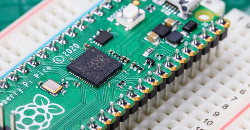
    The easiest way to use Pico, though, is to attach it to a breadboard – and for that, you’ll need to attach pin headers. You’ll need a soldering iron with a stand, some solder, a cleaning sponge, Raspberry Pi Pico, and two 20-pin 2.54 mm male header strips. If you already have a solderless breadboard, you can use it to make the soldering process easier.

    Sometimes 2.54 mm headers are provided in strips longer than 20 pins. If yours are longer, just count 20 pins in from one end and look at the plastic between the 20th and 21st pins: you’ll see it has a small indentation at either side. This is a break point: put your thumbnails in the indentation with the headers in both your left and right hands and bend the strip. It will break cleanly, leaving you with a strip of exactly 20 pins. If the remaining header strip is longer than 20 pins, do the same again so you have two 20-pin strips.

    Turn Raspberry Pi Pico upside-down, so you can see the silkscreen pin numbers and test points on the bottom. Take one of the two header strips and push it gently into the pin holes on the left-hand side of your Pico. Make sure that it’s properly inserted in the holes, and not just resting in the castellations, and that all 20 pins are in place, then take the other header and insert it into the right-hand side. When you’ve finished, the plastic blocks on the pins should be pushed up against your Pico’s circuit board.

    A guide to pin numbers are printed on the underneath of Raspberry Pi Pico

    Pinch your Pico at the sides to hold both the circuit board and the two pin headers. Don’t let go, or the headers will fall out! If you don’t have a breadboard yet, you’ll need some way to hold the headers in place while you’re soldering – and don’t use your fingers, or you’ll burn them. You can hold the headers in place with small alligator clips, or a small blob of Blu Tack or other sticky putty (Figure 1).

    Figure 1 You can hold the headers in place with sticky putty before soldering

    Solder one pin, then check the alignment: if the pins are at an angle, melt the solder as you carefully adjust them to get everything lined up.

    Use a breadboard

    If you have a breadboard, simply turn Raspberry Pi Pico upside down – remembering to keep the headers pinched – and push both the headers and your Pico into the holes on the breadboard. Keep pushing until your Pico is lying flat, with the plastic blocks on the pin headers sandwiched between your Pico and your breadboard (Figure 2).

    Figure 2 Alternatively, use a breadboard to hold the headers in place for soldering

    Look at the top of your Pico: you’ll see a small length of each pin is sticking up out of the pin holes. This is the part you’re going to solder – which means heating up both the pins and the pads on Pico and melting a small amount of a special metal, solder, onto them.

    Put your soldering iron in its stand, making sure the metal tip isn’t resting up against anything, and plug it in. It will take a few minutes for the tip of the iron to get hot; while you’re waiting, unroll a small length of solder – about twice as long as your index finger. You should be able to break the solder by pulling and twisting it; it’s a very soft metal.

    If your soldering stand has a cleaning sponge, take the sponge to the sink and put a little bit of cold water on it so it softens. Squeeze the excess water out of the sponge, so it’s damp but not dripping, and put it back on the stand. If you’re using a cleaner made of coiled brass wire, you don’t need any water.

    Warning! Hot solder!

    Soldering irons get very hot, and stay hot for a long time after they’re unplugged. Make sure that you put the iron in the stand when you’re not using it and don’t touch the metal parts – even after it’s unplugged. See Getting started with soldering for more information.

    Start to solder

    Pick up your soldering iron by the handle, making sure to keep the cable from catching on anything as you move it around. Hold it like a pencil, but make sure your fingers only ever touch the plastic or rubber handle area: the metal parts, even the shaft ahead of the actual iron tip, will be extremely hot and can burn you very quickly.

    Before you begin soldering, clean the iron’s tip: brush it along your sponge or coiled wire cleaner. Take your length of solder, holding it at one end, and push the other end onto the tip of your iron: it should quickly melt into a blob. If it doesn’t, leave your soldering iron to heat up for longer – or try giving the tip another clean.

    Putting a blob of solder on the tip is known as tinning the iron. The flux in the solder helps to burn off any dirt still on the end of the iron, and gets it ready. Wipe the iron on your sponge or cleaning wire again to clean off the excess solder; the tip should be left looking shiny and clean.

    Put the iron back in the stand, where it should always be unless you’re actively using it, and move your Pico so it’s in front of you. Pick up the iron in one hand and the solder in the other. Press the tip of the iron against the pin closest to you, so that it’s touching both the vertical metal pin and the gold-coloured pad on your Pico at the same time (Figure 3).

    Figure 3 Heat the pin and pad

    It’s important that the pin and the pad are both heated up, so keep your iron pressed against both while you count to three. When you’ve reached three, still keeping the iron in place, press the end of your length of solder gently against both the pin and pad but on the opposite side to your iron tip (Figure 4). Just like when you tinned the tip, the solder should melt quickly and begin to flow.

    Figure 4 Add a little solder

    The solder will flow around the pin and the pad, but no further: that’s because Pico’s circuit board is coated in a layer called solder resist which keeps the solder where it needs to be. Make sure not to use too much solder: a little goes a long way.

    Remove solder first

    Pull the remaining part of your solder away from the joint, making sure to keep the iron in place. If you pull the iron away first, the solder will harden and you won’t be able to remove the piece in your hand; if that happens, just put the iron back in place to melt it again. Once the molten solder has spread around the pin and pad (Figure 5), which should only take a second or so, remove the soldering iron. Congratulations: you’ve soldered your first pin!

    Figure 5 Now remove the iron

    Clean the tip of your iron on your sponge or brass wire, and put it back in the stand. Pick up your Pico and look at your solder joint: it should fill the pad and rise up to meet the pin smoothly, looking a little like a volcano shape with the pin filling in the hole where the lava would be, as shown in Figure 6.

    Figure 6 A well-soldered pin

    Once you’re happy with the first pin, repeat the process for all 40 pins on your Pico – leaving the three-pin ‘DEBUG’ header at the bottom empty.

    Remember to clean your iron’s tip regularly during your soldering, too, and if you find things are getting difficult, melt some solder on it to re-tin the tip. Make sure to keep refreshing your length of solder, too: if it’s too short and your fingers are too close to the soldering iron’s tip, you can easily burn yourself.

    When you’re finished, and you’ve checked all the pins for good solder joints and to make sure they’re not bridged to any nearby pins, clean and tin the iron’s tip one last time before putting it back in the stand and unplugging it. Make sure to let the iron cool before you put it away: soldering irons can stay hot enough to burn you for a long time after they’ve been unplugged!

    Finally, make sure to wash your hands – and celebrate your new skill as a soldering supremo!

    Tip! Four corners first

    Solder the four corner pins first. Take your time, don’t rush, and remember that mistakes can always be fixed.

    Soldering issues

    If the solder is sticking to the pin but not sticking to the copper pad, as in example A in Figure 7, then the pad wasn’t heated up enough. Don’t worry, it’s easily fixed: take your soldering iron and place it where the pad and pin meet, making sure that it’s pressing against both this time. After a few seconds, the solder should reflow and make a good joint. On the other hand, if the solder is too hot, it won’t flow well and you’ll get an overheated joint with some burnt flux (example B). This can be removed with a bit of careful scraping with the tip of a knife, or a toothbrush and a little isopropyl alcohol.

    Figure 7 Common soldering problems

    If the solder is entirely covering the pin, as in example C, you used too much. That’s not necessarily going to cause a problem, though it doesn’t look very attractive: so long as none of the solder is touching any of the pins around it, it should still work. If it is touching other pins (as in example D), you’ve created a bridge which will cause a short circuit.

    Again, bridges are easy to fix. First, try reflowing the solder on the joint you were making; if that doesn’t work, put your iron against the pin and pad at the other side of the bridge to flow some of it into the joint there. If there’s far too much solder still, you’ll need to remove the excess before you can use your Pico: you can buy desoldering braid, which you press against the molten solder to suck the excess up, or a desoldering pump to physically suck the molten solder up.

    Another common mistake is too little solder: if you can still see copper pad, or there’s a gap between the pin and the pad which isn’t filled in with solder, you used too little (example E). Put the iron back on the pin and pad, count to three, and add a little more solder. Too little is always easier to fix than too much, so remember to take it easy with the solder!

    Buy Get Started with MicroPython on Raspberry Pi Pico

    This tutorial is also included in our new book, Get Started with MicroPython on Raspberry Pi Pico. Pick up your copy of Get Started with MicroPython on Raspberry Pi Pico and learn about all the great things you can make with Pico.

    Get Started with MicroPython on Raspberry Pi Pico

  • Raspberry Pi Pico microcontroller: specifications, features and RP2040

    Raspberry Pi Pico microcontroller: specifications, features and RP2040

    Reading Time: 5 minutes

    Raspberry Pi Pico is a development board built around this powerful yet low-cost RP2040 microcontroller.

    Like Raspberry Pi computers, Raspberry Pi Pico features a pin header with 40 connections, along with a new debug connection enabling you to analyse your programs directly from another computer (typically by connecting it directly to the GPIO pins on a Raspberry Pi).

    The underside of Pico labels all the pins

    Pico is an incredibly interesting new device from Raspberry Pi. It offers a wealth of connectivity for external hardware – and enough processing power to handle complex tasks. All this in a compact board which costs less than a cup of coffee. You can pick up a Pico from just $4 / £3.60, or free on the latest edition of HackSpace magazine.

    Built with everyone from absolute beginners to professional engineers in mind, Raspberry Pi Pico represents the start of a new era for Raspberry Pi. We can’t wait to see what you all make with it.

    Get to know Raspberry Pi Pico

    Raspberry Pi Pico is a brand new, low-cost, yet highly flexible development board designed around a custom-built RP2040 microcontroller chip designed by Raspberry Pi.

    Raspberry Pi Pico – ‘Pico’ for short – features a dual-core Cortex-M0+ processor (the most energy-efficient Arm processor available), 264kB of SRAM, 2MB of flash storage, USB 1.1 with device and host support, and a wide range of flexible I/O options.

    A close up on the RP2040 chip that powers Pico

    The castellated pin headers ensure Pico is equally at home on a breadboard for experimentation as it is soldered onto a circuit board and driving a finished product. The high-performance processor cores coupled with RAM and storage give it impressive flexibility.

    A real highlight comes in the form of Programmable Input/Output (PIO) capabilities: bridging the gap between software and hardware, Pico’s PIO allows developers to define new hardware features in software – expanding its capabilities beyond any fixed-function device.

    Pico is set to prove itself not just an impressive new tool for Raspberry Pi users, but a must-have gadget for anyone investigating physical computing projects.

    Microcontroller

    RP2040 is a custom-built dual-core microcontroller, designed in-house at Raspberry Pi

    USB

    USB port on the end of Pico

    A micro USB port provides power and data, letting you communicate with and program Raspberry Pi Pico (by dragging and dropping a file)

    Bootsel

    The BOOTSEL button is important for using and modifying your Pico

    Hold the BOOTSEL (boot select) button when powering up Pico to put it into USB Mass Storage Mode. From here, you can drag-and-drop programs, created with C or MicroPython, into the RPI-RP2 mounted drive. Pico runs the program as soon as it is switched on (without BOOTSEL held down)

    Labelling

    Silkscreen labelling on the top provides orientation for the 40 pins, while a full pinout is printed on the rear

    Debugging

    Accessible debugging pins

    A Serial Wire Debug (SWD) header provides hardware debugging capabilities, letting you quickly track down problems in your programs

    Pins

    Yes, 'castellated' is a new word for us, too.

    Raspberry Pi Pico’s pins are castellated, allowing pin headers to be fitted for breadboard use or the entire board to be soldered as a flat module

    Raspberry Pi Pico specifications

    • RP2040 microcontroller chip designed by Raspberry Pi in the United Kingdom

    • Dual-core ARM Cortex-M0+ processor, flexible clock running up to 133MHz

    • 264kB of SRAM, and 2MB of on-board flash storage

    • Castellated module allows soldering direct to carrier boards

    • USB 1.1 Host and Device support

    • Low-power sleep and dormant modes

    • Drag & drop programming using mass storage over USB

    • 26 multifunction GPIO pins

    • 2× SPI, 2× I2C, 2× UART, 3× 12-bit ADC, 16× controllable PWM channels

    • Accurate clock and timer on-chip

    • Temperature sensor

    • Fast floating-point libraries in ROM

    • 8× Programmable IO (PIO) state machines for custom peripheral support

    Say hello to RP2040

    RP2040 is a low-cost microcontroller device, with the same focus on quality, cost, and simplicity that characterises the ‘big’ Raspberry Pi. Microcontrollers interact with the hardware of a board much like an application processor does in a larger device.

    Application processors like the Broadcom BCM2711 used in Raspberry Pi 4 are designed to run multiple programs under an operating system, like Raspberry Pi OS. These programs access external hardware through interfaces provided by the operating system.

    In contrast, microcontrollers like RP2040 interact directly with external hardware and typically run a single program from the moment you turn them on.

    A reel of Raspberry Pi Pico microcontroller boards ready for distribution

    Just as Raspberry Pi is an accessible computer, RP2040 is an accessible microcontroller, containing almost everything makers need to embed it inside a product.

    RP2040 is supported by both C/C++ and MicroPython cross-platform development environments, including easy access to runtime debugging. It has a built-in UF2 bootloader enabling programs to be loaded by drag-and-drop. The built-in USB can act as both device and host. Meanwhile, floating-point routines are baked into the chip for ultra-fast performance. It has two symmetric processor cores and high internal bandwidth, making it useful for signal processing and video applications. The chip has a relatively large amount of internal RAM but uses external flash storage, allowing you to choose how much memory you need.

    Microcontrollers are an exciting new area for Raspberry Pi fans to explore. See the RP2040 data sheet for more information.

    Behind the name 2040

    The post-fix numeral on RP2040 comes from the following:

    1. Number of processor cores (2)

    2. Loosely which type of processor (M0+)

    3. The amount of RAM, from the function floor(log2(RAM / 16kB)); in this case it’s 256kB

    4. The amount of non-volatile storage, from the function floor(log2(non-volatile / 16kB)), or 0 if no on-board non-volatile storage

    Translating the name of RP2040

  • Pirate Audio: Dual Mic review

    Pirate Audio: Dual Mic review

    Reading Time: 2 minutes

    This mini HAT looks very similar to other Pirate Audio products, with an integrated 1.3-inch colour LCD screen surrounded by four push-buttons. Located on either side of the board are two tiny digital microphones. These feature a SiSonic acoustic sensor, a serial ADC (analogue to digital converter), and an interface to convert the signal into the industry-standard 24-bit I2S format. In our tests, we found that they recorded sound with crystal-clear quality, although the mics aren’t that far apart so the stereo effect is limited.

    Portable clip recorder

    To make use of the Pirate Audio: Dual Mic, you’ll need to download the software; this involves entering three commands in a Terminal window to make all the necessary configuration changes behind the scenes.

    Recording an audio clip, with the volume levels shown on the LCD

    One of two Python code examples is an FFT (Fast Fourier transform) program that shows the levels of various sound frequencies on a graph. The other is a simple audio clip recorder which uses the tactile buttons to record, play, skip, and delete clips. Playback (using PulseAudio’s ‘upmix’ feature to avoid resampling) is via HDMI by default and we couldn’t get it to output through Raspberry Pi’s AV jack unless we played the clips separately with OMXPlayer. Portable playback is problematic on a Raspberry Pi Zero (which lacks AV output), too, so you’ll need to use Bluetooth or also attach an audio board using something like the HAT Hacker HAT.

    Verdict

    8/10

    High-quality audio capture in a small package that might be useful for a portable recorder or voice assistant project. It lacks its own audio output, though.

  • PiTubeDirect

    PiTubeDirect

    Reading Time: 3 minutes

    The 1980s gem inspired the affordable microcomputer we’ve come to know and love, so we adore how this project brings both together, using Raspberry Pi to enhance the BBC Micro by allowing another external CPU to be added.

    This idea is not new. BBC Micro maker Acorn included a port called Tube for this very purpose and it released a range of second processors to expand a machine with limited RAM. But Acorn’s original set of second processors can be expensive and tricky to find, so PiTubeDirect recreates them on Raspberry Pi.

    As such, BBC Micro enthusiasts can enhance their computers by adding a second 6502 or they can add external Z80, 32016 and ARM1 second processors – the latter used to develop the Archimedes range.

    “The second processors would take responsibility for running the current language and the user’s programs, leaving the BBC Micro host responsible for the keyboard, screen, and file system,” says project originator David Banks. “The Tube architecture was unique and very innovative at the time.”

    Timing it right

     David Banks originally created a 6502 second processor using a field-programmable gate array. Raspberry Pi reduced the cost, and this was the first prototype

    To enhance a BBC Micro in this way, users need a level-shifter HAT connected to Raspberry Pi’s GPIO interface which, in turn, is hooked to the BBC Micro’s Tube port using a 40-pin IDC cable. After installing the PiTubeDirect software to a microSD card, you simply plug and play.

    Yet getting to this point has been a challenge. “We were brainstorming what it would take to connect Raspberry Pi Zero to the Tube port with the absolute minimal amount of hardware,” recalls David, who began tinkering with the BBC Micro again in 2013 after discovering people were preserving the computer and developing new hardware and software.

    “The BBC Micro’s Tube interface is just an extension of the 6502 microprocessor bus and it uses 5V signal levels. Raspberry Pi uses more modern 3.3V signal levels, so the minimum hardware is just a couple of off-the-shelf level-shifter chips. 

    “But such a solution is only feasible if Raspberry Pi, in software, can do everything else, including responding to Tube requests in real time.” Achieving that was tricky.

    To the bare metal

    The original BBC Micro Model B had 32kB, but Acorn’s originally released 6502 second processor included a 50 percent faster 3MHz 65C02 CPU, as well as 64kB of RAM

    The wizardry used to interface the BBC Micro to a second processor was originally encapsulated in the Tube ULA custom chip. “Every second processor that Acorn produced contained one, providing a set of four bidirectional FIFOs that allow the ‘host’ and ‘parasite’ processors to communicate via a series of well defined messages, called the Tube Protocol,” explains David.

    Emulating this entailed using software running on Raspberry Pi and it needed to meet the hard real-time constraints of the 2MHz Tube interface.

    “We knew running a conventional operating system like Raspberry Pi OS would not yield the required guaranteed response time,” David says. “So, we dispensed with the operating system and engaged in ‚Bare Metal‘ programming, developing software by directly accessing the hardware of Raspberry Pi Zero.”

    To further resolve time-related problems, Dominic Plunkett joined the team and suggested moving the Tube ULA emulation code on to the GPU. Dominic also optimised the emulation speed of the 6502 to 292MHz, thus making it 150 times the speed of the original 2MHz BBC Micro. 

    One thing’s for sure, it’s been an education. “One of the more satisfying aspects of developing PiTubeDirect has been learning about programming at the lowest bare metal level,” notes David. “And that’s very much in the same manner that we would really get to know machines back in the 1980s.”