Kategorie: Reviews

  • Super 8 Kamera

    Super 8 Kamera

    Reading Time: 3 minutes

    Bennet is lucky enough to have a job that involves imagination, invention, and problem-solving. An engineer and professor of robotics, his role involves work developing mapping and camera-based assistance programs. In his free time, he focuses on building projects that spark his curiosity. “Raspberry Pi is a perfect platform for such projects because it eliminates most burdens that come with building embedded devices,” he says, citing the “excellent” Raspberry Pi and open-source software communities. 

    Mechanical marvels

    Super 8 cameras are “mechanical marvels that are destined to sit unused in drawers simply because you cannot buy the film cassettes any more,” he opines. And if you could, he calculates three minutes of footage would cost around €60 to develop. Troubled by this wasted potential, Bennet decided to create “an electronic film cassette that can be plugged into any Super 8 camera and make it usable again.” He used Raspberry Pi Zero W with a 5 MP camera mounted on a flex circuit board. He chose Raspberry Pi for the Zero W’s compact size and low price, plus the “excellent software support of camera and video encoder hardware.” He was also attracted by the possibility of adding wireless live video streaming. 

    Another important factor was that Bennet had recently put together a very similar project for an SLR still camera – involving fitting a Raspberry Pi Zero W completely inside the camera – which had proved popular. He hoped to use the same idea for the Super 8 camera. He was able to source the hardware including a photoresistor and motion-detecting LED from a supplier, Riechel, for around €50, and wrote code for the Super 8 Kamera project using the custom Python program and the picamera API. This program monitors the light detector for changes (such as when the user presses the camera’s record button) and starts recording and streaming at the same time. While Bennet’s code is specific to the Super 8 video camera, both the project idea and the picamera API can be adapted for use with other camera and video camera models.

    Fantastic facsimile

    Bennet spent around ten hours designing and 3D-printing the hardware, assembling the electronics, and writing the software. Fitting everything together so it fitted within the original Super 8 camera chassis involved three design versions. “It was quite hard to make the hardware fit into the cartridge. The camera placement and its cable proved to be an especially challenging origami riddle,” he comments. The results, however, were more than worthwhile: “It surprised me how much the digital footage looks like the original Super 8 movies. I did not implement any post-processing to make it look more like the original film, but still it looks remarkably similar. This gives the movies generated by my system a lot of character and a certain patina.

  • Environmental cargo logger

    Environmental cargo logger

    Reading Time: 3 minutes

    For this project’s requirements, a Raspberry Pi Zero became the obvious choice for Thinus.

    “There are numerous commercial environment loggers on the market to monitor cargo, but the client also wanted to have a visual record of the whole sea voyage. The requirements for the logger system were: to be powered by battery, low power consumption, low component costs, to allow the use of custom programming code, [and] consist of easy-to-come-by, off-the-shelf components. They also wanted flexibility – the ability to reuse the system components for other projects in the future. The sensor readings and photos would also be stored on a USB flash drive for easy collection… Raspberry Pi Zero checked all the boxes for the above requirements.”

    Potato stats

    Running continuously for 40 days is no real problem for a Linux-powered box like Raspberry Pi – there are several out there that have logged over 1000 days’ uptime – however, there’s no handy plug socket for Raspberry Pi to use here.

    To conserve as much power as possible, a PiJuice HAT with a power supply and a real-time clock was used to power on the system once a day for just five minutes to do its job.

    “Once Raspberry Pi was switched on, the temperature, humidity, and atmospheric pressure readings were taken and written to the USB flash drive,” Thinus explains. “As a failsafe, the data is also written to the SD card of Raspberry Pi.”

    Thinus describes it working as follows. During the start-up process, crontab events at reboot are scheduled to:

    – Take a photo after 45 seconds using a Bash script to:

    ◦Switch on the bright LED and take a photo with the Pi camera and save it to the SD card

    ◦Switch off the bright LED and switch on the infrared LED

    ◦Take an infrared photo with the camera and save it to the SD card

    ◦Copy the photos to the USB drive

    – Read the sensor data after 30 seconds with a Python script:

    ◦Write the measurements for the temperature, humidity, and atmospheric pressure to a log file on the SD card

    ◦Copy the log file to the flash drive

    – Set the PiJuice shutdown trigger for shutting down using a Python script.

    Tuber analysis

    Using results from the logger, the farm has put measures in place to reduce transit time for their sweet potatoes. The data also revealed some interesting stats, such as the big temperature shifts mainly occurring on the 1000 km journey from the farm to the harbour, and the unloading of the cargo at the destination. The potatoes also noticeably shrank over the course of the journey.

    “It worked very well, and for longer than anticipated,” Thinus mentions.

  • Virtual Minecraft birthday cake

    Virtual Minecraft birthday cake

    Reading Time: 2 minutes

    Virtualising baked goods

    While something like this could be in some way achieved in Minecraft Raspberry Pi Edition, that was not why a Raspberry Pi was used.

    “Raspberry Pi provided an easy way to interface with the analogue-to-digital converters needed to read the wind turbine voltages,” Stephen says. “Along with sufficient computing power to serve a web application from within the cake itself, using Raspberry Pi enabled me use the same software architecture (Python, Flask, HTML) as I have used professionally. Sourcing the right HAT to measure nine voltages was very easy.“

    Blowing on the wind turbines generates a small amount of voltage, enough to be detected as a change using an ADC.

    The virtual cake instead uses looping video overlaid with candle GIFs served via a web app in a clever way, as Stephen explains:

    “The application uses Flask to serve a web page which any device on the local network can access… a JavaScript loop is used to repeatedly send a POST request to the web server asking for the voltage from one of nine analogue-to-digital converters (the ADC board can support up to 16 candles). The code to interface with the ADCs and reply to the POST requests is written in Python and utilises the Flask and gpiozero libraries. All the code is available on GitHub.”

    Proof in the dessert

    Despite the best efforts of developers, sometimes an interface is not always clear to the user – especially when they’ve just turned nine.

    The guests quickly figured out what they had to do to blow out the candles

    “I was slightly nervous that the children would find it too abstract, but they worked it out pretty quickly,” Stephen mentions. “They saw the connection between the plastic wind turbines on the cake and the candles on the screen, and worked out that you could turn the on-screen candles off by blowing on the wind turbines. There was much laughter and smiles.

    The children were also very pleased to discover that there was actual cake underneath it all.”
    If only there were cake underneath every interactive Raspberry Pi project.

    There is space under the model cake for the electronics and the real cake

  • Opinion: Decade

    Opinion: Decade

    Reading Time: 2 minutes

    When Raspberry Pi came out, I had just started writing for a long defunct Linux magazine at a now dead publisher, and we were immediately enthralled. I spent years writing tutorials using a 256MB Raspberry Pi 1 Model B – turning Raspberry Pi into robots, media centres, file servers, routers, BOINC nodes, and much more. One day, I even managed to break the entire office LAN while playing around with network settings, oops. It was a lot of fun though, and I learned loads doing it.

    Late bloomer

    I was one of the kids that grew up in the late nineties and early noughties who experienced the loss of proper computing lessons at schools, so to be able to learn to code and learn practical programmable electronics in my twenties was a huge thing for me. It’s one of the reasons I landed on The MagPi in 2015, and more importantly, the reason I have stayed for around 80 issues.

    Seeing the passion of the community that first year was electric. When we put out issue 40 with Raspberry Pi Zero on the cover, we thought it might be popular, but we didn’t realise just quite how popular. It took about a week for the constant stream of messages from people wanting to get a copy to die down, and it took years for us to stop getting messages asking if we had any left at all.

    Since then, I’ve been through many things with Raspberry Pi. The launch of Raspberry Pi 3, the AIY Vision Kit we did with Google, sending Raspberry Pi to space, new cameras, Raspberry Pi 4, Raspberry Pi 400, Raspberry Pi Pico, and recently Raspberry Pi Zero 2 W, just to name a few.

    Now where?

    As the second decade of Raspberry Pi looms ahead, my enthusiasm hasn’t died down a bit. I still get new ideas every month for something to do with Raspberry Pi, and I will never cease to be amazed at the creativity of the community and how much they’ve supported us over the years. I’ll be right here with you to see what 2022 brings to Raspberry Pi, and the ever-changing world it’s helping.

  • DACBerry 400 S review

    DACBerry 400 S review

    Reading Time: 2 minutes

    The DACBerry 400 S (£17/$19) fits onto the GPIO header at the rear of Raspberry Pi 400. While it’s fairly obvious which way up the board should go, care needs to be taken to line up its header with the GPIO pins correctly – with a small gap showing at the Pin 1 end.

    Get the alignment wrong and not only will you get no sound, but you may damage the board. This is something manufacturer OSA Electronics will be addressing in the second batch of boards, by introducing a small bump in the middle, to line up with a notch in the GPIO header surround.

    DACBerry 400 S: Let there be sound

    A one-line Terminal command installs the software needed to drive the DACBerry 400 S. At the time of writing, this required the earlier ‚buster‘ version of Raspberry Pi OS, but it should be available in Bullseye soon. After rebooting, the audio will be routed through the DACBerry – with Raspberry Pi 400’s audio chip disabled, so it’s not easy to switch back if needed. It also works with OSMC and LibreELEC, among other OSes.

    The line-out audio signal is strong enough for decent volume on connected headphones, or you can use powered speakers or an amp. The sound quality is very good with a nice warm tone and strong bass, possibly due to DSP’s integrated low-pass filter. The audio can be adjusted using the numerous settings in alsamixer, but OSA plans to introduce a GUI-based tool for this.

    A bonus is the ability to connect a microphone for recording, using the same 3.5 mm socket – OSA is also planning another DACBerry 400 model with a separate mic socket. 

    DACBerry 400S verdict

    If you need a separate audio output (and/or mic input) for your Raspberry Pi 400, this provides one at little cost.

    8/10

  • Big Boxes

    Big Boxes

    Reading Time: 3 minutes

    The Big Easy

    Jangala co-founder and head of technology Rich Thanki has been fiddling with gadgetry and taking electronics apart “as long as I can remember”. A huge fan of wireless technology, Rich worked on projects with Microsoft bringing connectivity to people in sub-Saharan Africa before founding Jangala with Samson Rinaldi, who managed the CAD and hardware design aspects.

    Each Big Box is a briefcase-sized device, designed to be simple to set up and take advantage of an available wireless connection to offer WiFi access to hundreds of users at a time. “Scalable high-quality WiFi without the need for costly technical expertise” characterises Jangala’s single-box approach to providing internet access when and where it may be needed.

    Each box provides secure wireless access, weighs just 1.9 kg, and fits in a small backpack

    This is the first of Jangala’s projects to use Raspberry Pi products. “I think the first of many,” says Rich.

    Jangala’s updated purple box is now faster, more capable, and more rugged, the team explains, with the wireless antennas having been moved inside the box to protect them from the elements, plus twin modems that allow Big Box to connect to networks ranging from 2G networks to 5G. It was largely this aspect that prompted the switch to Raspberry Pi since it can handle the gigabit speeds that 5G networks offer.

    Other components were sourced from “absolutely all over the place”, but the use of OpenWRT and the support of the Linux community were absolutely crucial. Rich also credits amazing manufacturers in China who designed the incredibly useful things that can’t be found anywhere else, “everything from the perfect boost converter to little waterproof slots for SIM cards”.

    Tech for good

    “The role of Raspberry Pi in Big Box is essentially to run the show,” says Rich. “It’s really the brains and brawn of the system. We are able to control and see Big Boxes in the field by talking to Raspberry Pi. It routes every bit of traffic, which is no easy feat. We’ve a unique software setup to ensure security and it’s remotely updatable, so we have to use U-Boot as a second-stage bootloader.

    Big Box and Lenovo devices support online education courses in Kalobeyei settlement, Kenya

    Rich says working with Raspberry Pi 4 has been great because of the community, really accessible documentation, and standards that are open-source. “It’s made a huge difference for us. We wouldn’t have been able to do this on any other device,” he notes.

    Although Big Box is Jangala’s first Raspberry Pi experience, it won’t be their last. “Our next two projects will tackle other aspects of infrastructure which are really important in humanitarian settings, mainly power and edge computing. In both these cases, Raspberry Pi provides things that could easily be at the heart of these projects.”

    For anyone else planning on designing products for social good, Rich says, “Focus on what you have to do to get the design into the hands of people and making a difference as soon as possible. This might run against the grain of people who want to be perfect and neat. Don’t let the perfect be the enemy of the good.”

    Delivery of Big Boxes at Kakuma refugee camp, Kenya, where they will help support women and disadvantaged youths gain education and employment

  • Make a Build HAT game controller

    Make a Build HAT game controller

    Reading Time: 11 minutes

    You’ll need…

    Set up Build HAT

    Before you begin, you’ll need to have set up your Raspberry Pi computer and attached a Build HAT. If you have a Maker Plate™, mount your Raspberry Pi to it using M2 bolts and nuts, making sure your Raspberry Pi is mounted on the side without the ‘edge’.

    Mounting Raspberry Pi this way round enables easy access to the ports as well as the SD card slot. The Maker Plate will allow you to connect Raspberry Pi to the main structure of your dashboard more easily (this is an optional extra).

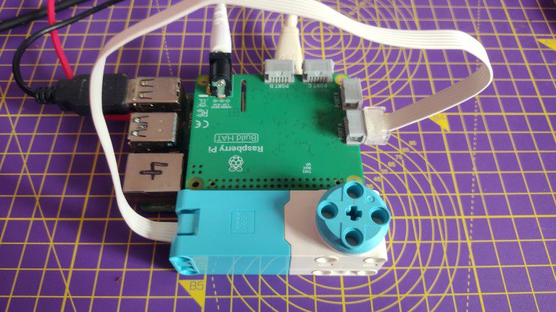
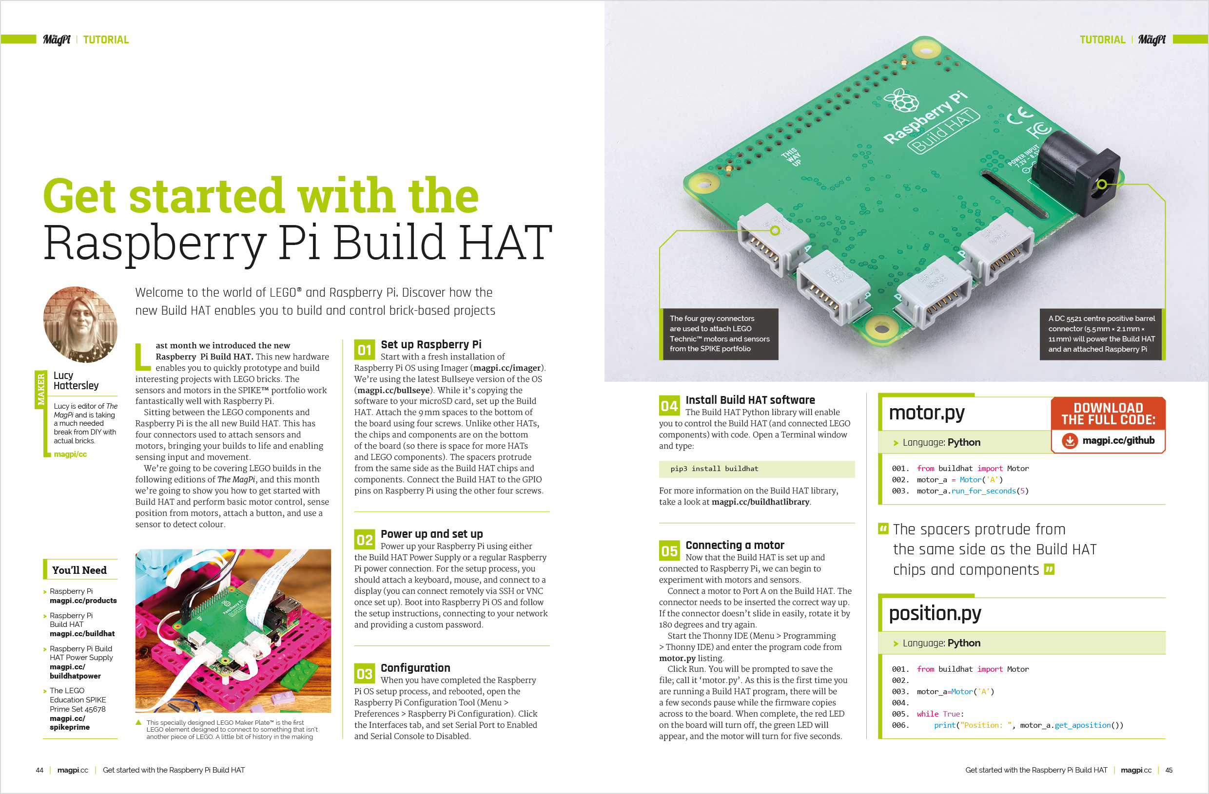
    Line up the Build HAT with your Raspberry Pi, ensuring you can see the ‘This way up’ label. Make sure all the GPIO pins are covered by the HAT, and press down firmly.

    You should now power your Raspberry Pi using the 7.5 V barrel jack on the Build HAT, which will allow you to use the motors.

    Connect a motor to port A on the Build HAT

    You will also need to install the buildhat Python library. Open a Terminal window on your Raspberry Pi and enter:

    sudo pip3 install buildhat

    Press ENTER and wait for the ‘installation completed’ message.
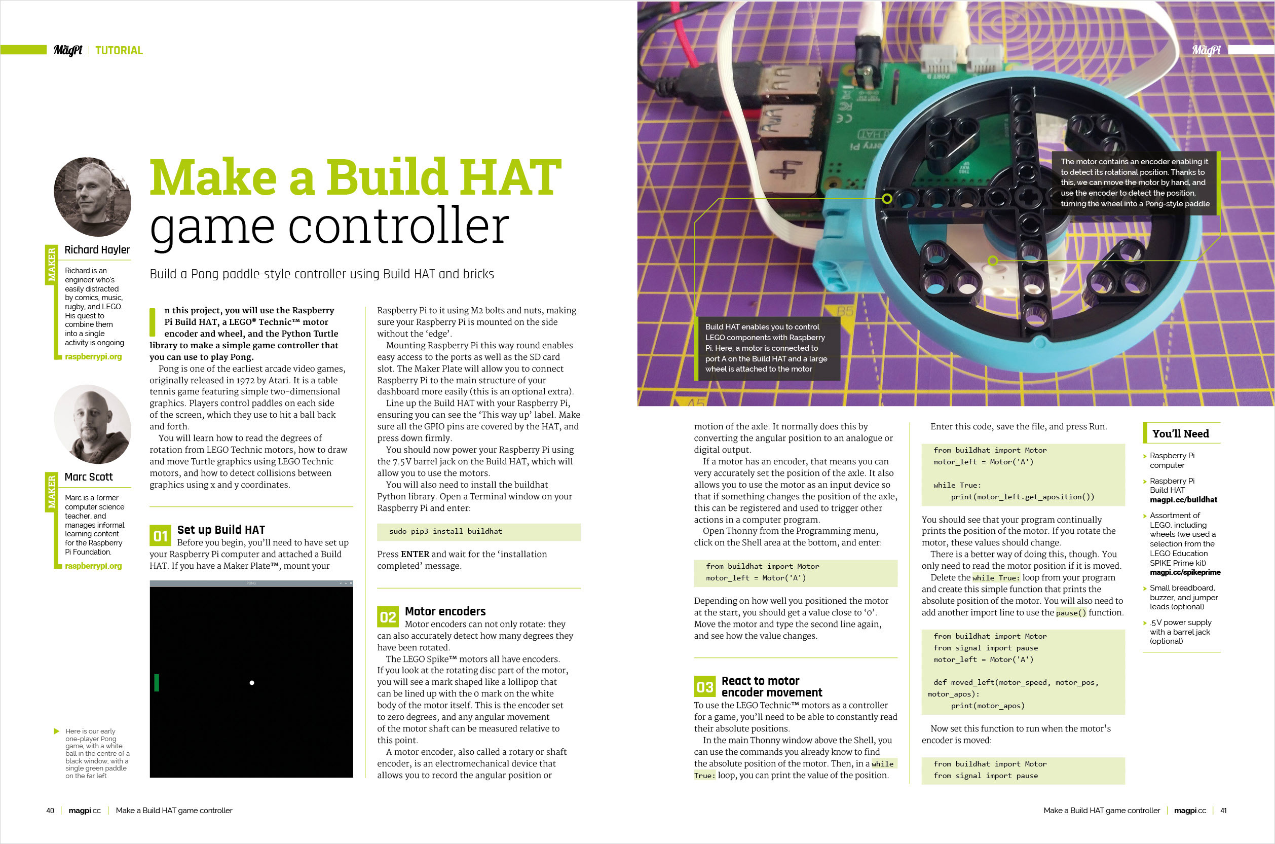
    Motor encoders

    Motor encoders can not only rotate: they can also accurately detect how many degrees they have been rotated.

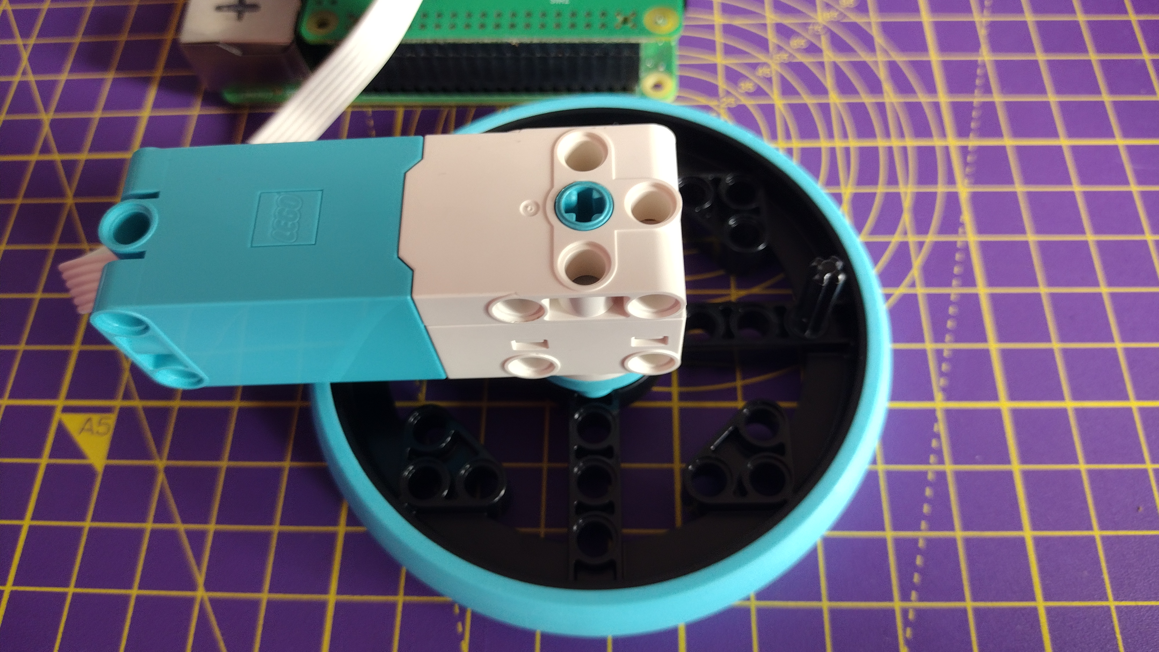
    The LEGO Spike™ motors all have encoders. If you look at the rotating disc part of the motor, you will see a mark shaped like a lollipop that can be lined up with the 0 mark on the white body of the motor itself. This is the encoder set to zero degrees, and any angular movement of the motor shaft can be measured relative to this point.

    A motor encoder, also called a rotary or shaft encoder, is an electromechanical device that allows you to record the angular position or motion of the axle. It normally does this by converting the angular position to an analogue or digital output.

    If a motor has an encoder, that means you can very accurately set the position of the axle. It also allows you to use the motor as an input device so that if something changes the position of the axle, this can be registered and used to trigger other actions in a computer program. Open Thonny from the Programming menu, click on the Shell area at the bottom, and enter:

    from buildhat import Motor
    motor_left = Motor('A')

    Depending on how well you positioned the motor at the start, you should get a value close to ‘0’. Move the motor and type the second line again, and see how the value changes.

    React to motor encoder movement

    To use the LEGO Technic™ motors as a controller for a game, you’ll need to be able to constantly read their absolute positions.

    In the main Thonny window above the Shell, you can use the commands you already know to find the absolute position of the motor. Then, in a while True: loop, you can print the value of the position.

    Enter this code, save the file, and press Run.

    from buildhat import Motor
    motor_left = Motor('A') while True: print(motor_left.get_aposition())

    You should see that your program continually prints the position of the motor. If you rotate the motor, these values should change.

    There is a better way of doing this, though. You only need to read the motor position if it is moved.

    Delete the while True: loop from your program and create this simple function that prints the absolute position of the motor. You will also need to add another import line to use the pause() function.

    from buildhat import Motor
    from signal import pause
    motor_left = Motor('A') def moved_left(motor_speed, motor_pos, motor_apos): print(motor_apos)

    Now set this function to run when the motor’s encoder is moved:

    from buildhat import Motor
    from signal import pause
    motor_left = Motor('A') def moved_left(motor_speed, motor_pos, motor_apos): print(motor_apos) motor_left.when_rotated = moved_left
    pause()

    Run your code and you should see the values printed out in the Shell change when the motor is moved.

    Make your Pong screen

    Open a new file in Thonny and add the following code to import the Turtle, time, and Build HAT libraries, and then set up a screen. Run the file and you should see a black window with the title ‘PONG’ open.

    from turtle import Screen, Turtle
    from time import sleep from buildhat import Motor game_area = Screen() #Create a screen game_area.title("PONG") #Give the screen a title game_area.bgcolor('black') #Set the background colour game_area.tracer(0) #Give smoother animations

    The Turtle library also has a useful way of setting the co-ordinates for a screen area. Add this line to your program:

    game_area.tracer(0) game_area.setworldcoordinates(-200, -170, 200, 170)

    This creates a rectangular window 400 pixels wide and 340 high, with 0 being in the centre (see below).

    The co‑ordinates for the game area in our version of Pong

    Now, you need to update your game area, to see the paddle and ball. Add a game loop to the bottom of your code, and call the update() method.

    while True: game_area.update()

    Run your code and you should see a black window appear. Next, you can make a ball by using a Turtle that is set to be a white circle. The ball should start in the middle of the screen, and shouldn’t draw a line when it moves. Above your while True: loop, add the following code:

    ball = Turtle() ball.color('white') ball.shape('circle') ball.penup() ball.setpos(0,0) while True:

    Run your code again. You should see a white ball appear in your window. Next, you can set up a paddle in the same way. It will be a green rectangle, and positioned on the far left of the screen.

    paddle_left = Turtle() paddle_left.color('green') paddle_left.shape('square') paddle_left.shapesize(4, 1, 1) paddle_left.penup() paddle_left.setpos(-190, 0) 

    Run your code and you should see your ball and paddle.

    Move the ball

    The ball is going to bounce around the screen, so two variables are needed to keep track of its speed in both the ‘x’ and ‘y’ directions. These numbers can be larger to make the game harder, or smaller to make the game easier.

    ball.speed_x = 1 ball.speed_y = 1 

    You can check where a Turtle is by using turtle.xcor() and turtle.ycor() to find the ‘x’ and ‘y’ co-ordinates, respectively. So to make the ball move, you can combine the position and speed.

    Add the lines below to your program:

    while True: game_area.update() ball.setx(ball.xcor() + ball.speed_x) ball.sety(ball.ycor() + ball.speed_y)

    Run the program and see what happens! The ball should move diagonally upwards towards the top right corner of the game area… and then keep on going! If you want your game to be fast and challenging, you can increase the speed_x and speed_y values to make the ball move more quickly.

    The ball should bounce off the top wall rather than disappear off the screen. To do this, the speed can be reversed, making the ball travel in the opposite direction, if its ‘y’ position is greater than 160.

    Add the following code into your game loop and run it.

    while True: game_area.update() ball.setx(ball.xcor() + ball.speed_x) ball.sety(ball.ycor() + ball.speed_y) if ball.ycor() > 160: ball.speed_y *= -1 

    Run your code again, and the ball should bounce off the top of the screen, but disappear off the right of the screen.

    In the same way that the code checks the upper ‘y’ position of the ball, to make it bounce, it can check the right ‘x’ position and the lower ‘y’ position, in your game loop.

    Add these checks on the ball’s position.

     if ball.ycor() > 160: ball.speed_y *= -1 if ball.xcor() > 195: ball.speed_x *= -1 if ball.ycor() < -160: ball.speed_y *= -1 

    The ball should now bounce around the screen, and fly off the left edge. Next, you will control your paddle to reflect the ball back from the left edge.

    Control the paddle

    The LEGO Spike motor is going to be used to control the position of the paddle, but you don’t want to be able to make full turns.

    A simple way to limit the motion of the wheel is to add a LEGO element to prevent the wheel turning through a complete rotation.

    Line up the encoder marks on your motor using the wheel, like before. Insert a peg or axle as close to level with the markers as possible.

    Attach a peg to the rear of the wheel to prevent the wheel from spinning indefinitely

    Add a line to create the motor_left object after the import line.

    from buildhat import Motor motor_left = Motor('A')

    Now a new variable is needed to keep track of the location of the paddle. This will be called pos_left and set to 0.

    ball.speed_x = 0.4 ball.speed_y = 0.4 pos_left = 0

    Create a function for the paddle that will run when the motor encoder moves. Note that it uses a global variable so that it can change the value of the pos_left variable.

    def moved_left(motor_speed, motor_rpos, motor_apos): global pos_left pos_left = motor_apos

    Now add a single line that will use that function each time the motor is moved. It can be just before your while True: loop.

    motor_left.when_rotated = moved_left

    Then, add a line to the while True: loop to update the paddle object on the screen to the new position.

     if ball.ycor() < -160: ball.speed_y *= -1 paddle_left.sety(pos_left) 

    Run your code and then turn the wheel on your motor encoder. You should see your paddle moving up and down the screen.

    In case there are errors, your code should currently look like pong.py.

    Paddle collisions

    The game is nearly complete – but first you need to add some extra collision detection that covers the ball hitting the paddle.

    Within the while True: loop, check if the ball’s ‘x’ position is within the horizontal area covered by the paddle. Also use an and to check the ball’s ‘y’ position is in the vertical line in which the paddle moves.

    paddle_left.sety(pos_left) if (ball.xcor() < -180 and ball.xcor() > -190) and (ball.ycor() < paddle_left.ycor() + 20 and ball.ycor() > paddle_left.ycor() - 20): ball.setx(-180) ball.speed_x *= -1

    Try the program out. You should be able to bounce the ball off your paddle and play a solo game of ‘squash’!

    Now you have a way of preventing the ball from disappearing off-screen, it’s time to think about what happens if you fail to make a save. For now, let’s just reset the ball back to the start.

    Add this code within the while True: loop:

     ball.speed_x *= -1 if ball.xcor() < -195: #Left ball.hideturtle() ball.goto(0,0) ball.showturtle()

    Once you’re happy with the various settings, it’s time to add in the second paddle. Using what you’ve created for the left-hand paddle as a starting point, add a second paddle on the right-hand side of the game area.

    First of all, connect a second LEGO Technic motor to the Build HAT (port B) and set it up in the program.

    motor_left = Motor('A') motor_right = Motor('B')

    You can copy and paste your code for setting up your left paddle, and change the name and values for your right paddle. Create your right paddle.

    paddle_left = Turtle() paddle_left.color('green') paddle_left.shape("square") paddle_left.shapesize(4,1,1) paddle_left.penup() paddle_left.setpos(-190,0) paddle_right = Turtle() paddle_right.color('blue') paddle_right.shape("square") paddle_right.shapesize(4,1,1) paddle_right.penup() paddle_right.setpos(190,0) 

    Add a variable for the right paddle position, a function for the paddle, and the line to call the function when the right motor is moved.

    pos_left = 0 pos_right = 0 def moved_left(motor_speed, motor_rpos, motor_apos): global pos_left pos_left = motor_apos def moved_right(motor_speed, motor_rpos, motor_apos): global pos_right pos_right = motor_apos motor_left.when_rotated = moved_left motor_right.when_rotated = moved_right 

    Add a line to update the paddle on screen to the while True: loop:

     paddle_left.sety(pos_left) paddle_right.sety(pos_right)

    Currently, the ball will bounce off the right-hand wall. Modify the lines of your program that make that happen so that the ball is instead reset to the centre. Now add a similar condition for the right paddle as you did with the left, to handle collisions.

     if (ball.xcor() < -180 and ball.xcor() > -190) and (ball.ycor() < paddle_left.ycor() + 20 and ball.ycor() > paddle_left.ycor() - 20): ball.setx(-180) ball.speed_x *= -1 if (ball.xcor() > 180 and ball.xcor() < 190) and (ball.ycor() < paddle_right.ycor() + 20 and ball.ycor() > paddle_right.ycor() - 20): ball.setx(180) ball.speed_x *= -1 

    You should now be able to enjoy a basic two-player game of Pong. Your code should currently look like two_player_basic.py.

    Improve your project

    There are a few additional features you can add to finish off your game. Keep track of the score by using two variables (one for each player) and update them whenever a round is lost.
    First of all, declare the new variables towards the top of the program and set the score to zero.

    score_r = 0
    score_l = 0

    Whenever a ball is missed, increment the appropriate score variable by one. There are two conditional tests you’ll need to modify.

     if ball.xcor() > 195: #Right ball.hideturtle() ball.goto(0,0) ball.showturtle() score_r+=1 if ball.xcor() < -195: #Left ball.hideturtle() ball.goto(0,0) ball.showturtle() score_l+=1

    Now you need to display the score in the game area. You can use a fourth Turtle to do this. Add the following to your program after the creation of the paddle and ball Turtles, but before the while True: loop.

    writer = Turtle()
    writer.hideturtle()
    writer.color('grey')
    writer.penup()
    style = ("Courier",30,'bold')
    writer.setposition(0,150)
    writer.write(f'{score_l} PONG {score_r}', font=style, align='center')

    You can look at the documentation for the Turtle library to see what other options there are for how the text is displayed.

    If you run your program now, the score and Pong legend should appear, but the scores themselves won’t get updated.

    Find the two conditionals for each of the scoring situations – when the ball is missed by a paddle and disappears to the left or right – and update the score by rewriting the new value.

     writer.clear() writer.write(f'{score_l} PONG {score_r}', font=style, align='center')

    Adding a buzzer

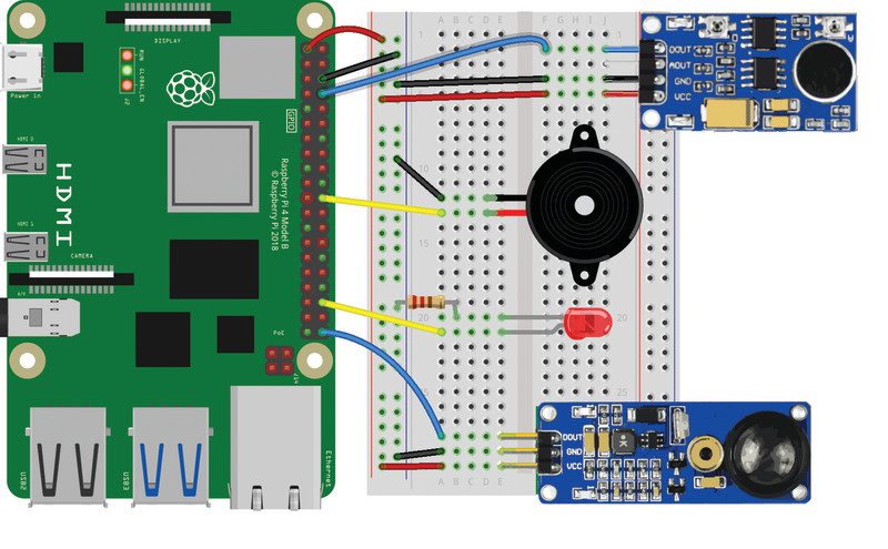
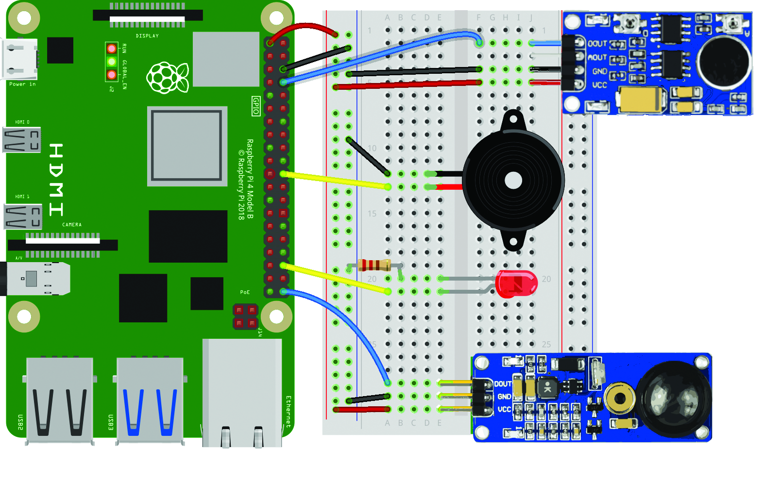
    To include some simple sound effects, connect a buzzer to the GPIO pins on Raspberry Pi.
    Instead of using a breadboard, you could use jumper leads with female sockets at both ends and poke the legs of the buzzer into the socket. Then use some LEGO elements to mount the buzzer so that it doesn’t flop around and become disconnected during frantic gaming sessions.

    Now add the gpiozero library to the list of imports at the start of your program:

    from gpiozero import Buzzer

    Then, make the buzzer available for the program to use, by setting which pin you have connected the positive (+) leg to. here, we used GPIO 17.

    buzz = Buzzer(17)

    If you didn’t use GPIO 17, change the value to reflect the pin your buzzer is connected to.

    Now, whenever the paddle and ball make contact, you want the game to play a short tone.

    Add this line to each action part of the collision detection if conditionals for the ball and paddle:

    buzz.beep(0.1,0.1,background=True)

    Then add a line to play a longer tone whenever the player misses the ball.

    buzz.beep(0.5,0.5,background=True)

    You can read more about the options available with buzzers in the GPIO Zero documentation.

    Improve the Pong game

    Here are some ideas to improve your game of Pong. You can add even more randomness to the speed and trajectory of the ball, and make the ball move faster as the game progresses.

    Right now the game carries on forever – consider having a target score that a player must achieve in order to win and then start a new set of rounds; change the scoring method to count how many times the players return the ball to one another, and reset when someone misses. Or, introduce some haptic feedback, so that the motors turn a small amount when a point is lost.

    At the moment it doesn’t matter what part of the paddle connects with the ball; it will always bounce off at the same angle as it hit. Modify the collision code so that the angle becomes more obtuse if the ball makes contact close to the end of the paddle.

    Create more games that use the LEGO Technic motors as controllers.

    How about a game in the style of Angry Birds, where two controllers are used to set the launch trajectory and the amount of force applied to the catapult?

  • Argon IR Remote review

    Argon IR Remote review

    Reading Time: < 1 minute

    Thankfully, Argon40 has been watching other tech design teams rather than those of most modern TVs. What you get for your very reasonable £9 is a minimalist, slim remote with just enough to make controlling Kodi a breeze. Basic directional control, selection, volume, and standard navigation work alongside a power button that works out-of-the box with any Raspberry Pi 4, regardless of operating system. It’s light too, at just 65 g with two AAA batteries.

    You’ll need an Argon ONE case (or the forthcoming EON) to use the Argon IR

    More than media

    If media centres are not your thing, or you have other epic plans for a remote control, Argon40 provides software that allows you to assign any key press to a button using the standard LIRC library with ease, making the addition of IR remote control to your project easier than ever before. In our tests, this worked flawlessly. However, we did have some issues configuring Kodi due to some missing steps in the supplied instructions. Once resolved, the remote performed admirably from across the room.

    Although the setup instructions could be improved, Argon40 has delivered a sleek, simple, and reasonably priced IR remote, both for Raspberry Pi media centres and homebrew projects.

    9/10

  • PicoLight

    PicoLight

    Reading Time: 3 minutes

    Small but mighty

    Alexandra describes PicoLight’s user experience as “pretty simple”. It’s made up of two fully customised PCBs and an acrylic panel sandwiched together. One PCB is a LiPo battery shield including a charging circuit and a power switch, while the other PCB is a 4×4 NeoPixel matrix with a Raspberry Pi Pico soldered onto the back. It also features a rotary encoder with a push-button, “used to switch between the functioning modes: colour adjustment, brightness adjustment, and rainbow mode, in which the LEDs cycle through all the colours.”

    The team initially connected an external battery to Pico’s micro USB port, but Alexandra says that they soon realised that portability was key, “so we ended up designing our own battery shield as well.”

    The 4×4 NeoPixel matrix in rainbow cycle mode

    All of this has resulted in a very neat-looking and compact end product. As the PicoLight measures just 52×52 mm, they were a little concerned about how they would fit all of the features on it, but “then it hit us that we can actually build vertically, and add a new layer for every new feature we want to integrate, such as the battery charging module,” says Mihnea.

    They’ve found it a useful tool on a day-to-day basis and while PicoLight’s main purpose is adding a “dash of colour to macro photography… we’ve also used it to add a rather nice touch to video calls,” Mihnea adds.

    In the limelight

    The response to PicoLight received so far has been hugely encouraging. “PicoLight ended up being much more popular than we’ve expected,” says Alexandra. “Some of our photographer friends asked for PicoLights to use in their shoots.”

    While considering a few improvements, including the possibility of using the RP2040 chip on a custom board rather than the entire Pico, Constantin tells us that since the feedback has been so positive, and everybody asked where they can buy it, they are pondering crowdfunding the project to bring it to mass production.

    The NeoPixel PCB is sandwiched between an acrylic diffuser panel and the LiPo battery shield

    The team are well-accustomed to using Raspberry Pi boards in their projects. “We have worked a lot with Raspberry Pi development boards for various IoT projects,” says Constantin, “like automated points of sale, magic mirrors, and automated crypto trading bots to name a few, and we are excited about exploring the Pico microcontroller range.”

    They have also, generously, made this project open-source, as Constantin explains: “We foresee using the Raspberry Pi variants in lots of future projects since they offer so much flexibility and the support of the community is so good. We’re also actively giving back whenever we can by open-sourcing our [Raspberry] Pi-based projects.”

    If you’d like to try and make your own PicoLight, step-by-step instructions are available on Hackster, and Mihnea thinks that any intermediate-level maker with a hot plate or DIY reflow oven would be able to achieve this make, as the right tools “make short work of this project.”

  • New User Guide for 2022 in The MagPi magazine issue #113

    New User Guide for 2022 in The MagPi magazine issue #113

    Reading Time: 3 minutes

    Raspberry Pi OS (‚bullseye‘)

    There’s a brand new version of Raspberry Pi OS, based upon Debian ‘bullseye’. The interface has a fresh look (if your Raspberry Pi has 2GB of RAM or more). The new video driver and updated version of Chromium make video playback better than ever. And Raspberry Pi 4 and Raspberry Pi 400 owners can look forward to a speed boost. There’s a whole bunch of stuff to discover and a few surprises that can trip up regular Raspberry Pi owners. Pick up the new edition to read all about it!

    Raspberry Pi Gaming

    We all know Raspberry Pi is incredible for old school gaming. But what about new games? Discover no-emulation gaming with our guide to the best games available for the increasingly powerful computer.

    Old School Minitel Laptop

    We’ve got a lot of time for the classics here at The MagPi. This Minitel terminal was popular in France in the 1980s, where Minitel was an online predecessor to the internet. One maker has remade a Minitel with Raspberry Pi, blending some of the best of the old with the new.

    Make a Build HAT game controller

    This month we have been experimenting with LEGO® bricks and Raspberry Pi. We set about building a pair of Pong-style video game controllers using the encoders on motors and some oversized wheels.

    Composite video with Zero 2 W

    Not many folks know you can hook up Raspberry Pi to classic CRT (cathode ray tube) television sets. This setup is great if you’re looking to play digital videos with a classic style. CRT also enables you to faithfully recreate a retro computer. Zero 2 W has moved the video out to test pins on the back of the board, and PJ’s tutorial will show you how it now all works.

    Interview with Stewart Watkiss

    Get to know members of Raspberry Pi’s community in each edition of The MagPi magazine. This month we chat with Stewart Watkiss (aka Penguin Tutor). Stewart has been creating projects with Raspberry Pi right from the beginning and has been involved with many Raspberry Pi events; he has also written books on Raspberry Pi and electronics.

    The MagPi magazine issue 113 is available as a free digital download, or you can purchase a print edition from the Raspberry Pi Press store. Subscribe to The MagPi in print for 12-months and get a free Raspberry Pi Zero 2 computer.

  • Win! One of five PicoSystem consoles

    Win! One of five PicoSystem consoles

    Reading Time: < 1 minute

    Subscribe

  • Make an intruder alarm with Raspberry Pi

    Make an intruder alarm with Raspberry Pi

    Reading Time: 6 minutes

    Intruder Alarm: You will need

    Connect the laser sensor

    Think of all those movies where a secret agent or thief has to get past some lasers guarding an object: break the beam and the alarm will go off. That’s what we’ll be doing here.

    For this tutorial, we’re using the laser sensor from the [Waveshare Sensors Pack](magpi.cc/wavesensors), available in the UK from The Pi Hut, and also sold separately, but any similar sensor should work in a similar way.

    It continually emits a laser beam, and its receiver only detects a reflected beam of the exact same wavelength (650 nm), so it won’t be triggered by other visible light. When it detects the beam, its digital pin outputs 1; when the beam is broken, it’s 0.

    With the power turned off, connect the laser sensor to Raspberry Pi as in Figure 1. We’re powering it from Raspberry Pi’s 3V3 pin, grounding it with a GND pin (both via the breadboard side rails), and the digital output (marked DOUT on the sensor) is going to GPIO 21.

    Warning!

    The laser sensor used here continually emits a laser beam. Be very careful not to point it towards anyone’s head as it could potentially damage their eyesight.
    More information on laser safety.

    Laser positioning

    With the laser sensor wired up, turn on Raspberry Pi. You should see the sensor’s red power LED (on the right) light up if it’s connected correctly. It should also be emitting a laser beam from the metal tube, so be careful never to look straight into it.

    Aim the beam at a nearby wall (up to 1.5 m away) and check that its left LED (marked DAT) is lit, confirming that it is detecting the laser beam. You may need to adjust the vertical and horizontal tilt of the sensor, or move it closer to the wall.For the finished alarm, we recommend you place the laser sensor fairly near the floor so that anyone walking through it will break the beam and it won’t be anywhere near their eyes.

    Laser test

    To begin, we’ll create a simple Python program, as in the laser_test.py listing, to read the sensor’s digital output and print out a message to show when the beam is broken. From the desktop menu, go to Programming and open the Thonny IDE to start coding.

    from gpiozero import Button laser = Button(21)
    msg = "" while True: if laser.value == 0: msg = "Intruder!" else: msg = "All clear" print(msg, end = "\r")

    As before, we’re using the GPIO Zero library; at the top of the code, we import the Button method from it. We’ll use this to sense when the digital output from the sensor is high, in effect the equivalent of a push-button being pressed. As it’s connected to GPIO 21, we assign the laser object to this with laser = Button(21).

    In an infinite while True: loop, we check whether the pin is low (if laser.value == 0), which means the beam has been broken, and set the message (msg1 variable) that we’ll be printing to the Shell area accordingly. In our print statement, we add the end = „\r“ parameter so the message is always printed on the same line.

    Run the laser_test.py code and then try breaking the beam with your hand and see if the message changes to ‘Intruder!’. You may find that it works better with your hand more distant from the sensor. Even if the DAT LED only flickers off momentarily, that should be enough to trigger our alarm later.

    Add a sound sensor

    Now that we have our laser sensor working, let’s make our setup even more intruder-proof by adding a sound sensor. We’re using a Waveshare sound sensor for this, as featured in the Sensors Pack, but other similar sensors are available, along with USB mics.

    Our sensor has pins for analogue and digital outputs, but we only need the digital output for our alarm. With the power turned off, we connect that pin (DOUT) to GPIO 14, and the VCC and GNC pins to 3V3 and GND (shared with the laser sensor via the breadboard side rails), as in Figure 1.

    Turning Raspberry Pi back on, you’ll see the power LED on the left of the sound sensor is lit up. Make a loud noise and you should see the LED on the right light up to show it has been detected.

    Sound test

    Let’s create a similar program to test the sensor. In the sound_test.py code listing, we assign the sound object to GPIO14 with sound = Button(14). Again, we use the Button method to detect when the pin is triggered.

    from gpiozero import Button sound = Button(14)
    msg = "" while True: if sound.value == 1: msg = "Intruder!" else: msg = "All clear" print(msg, end = "\r")

    This time in our while True: loop, we test whether the pin is high (there is a loud enough noise to trigger the sound sensor). As before, this determines which message (in the msg1 variable) is printed to the Shell area.

    Make a noise

    Now it’s time to test our sound sensor to check it’s wired up and working correctly. Run the sound_test.py Python code and then made a loud noise to make the DAT LED on the right of the sensor light up. You may find that you need to be noisy for a second or so and that there’s a short delay before the message changes briefly from ‘All clear’ to ‘Intruder!’.

    If you’re having trouble triggering it, try altering the sensitivity of the sound sensor by adjusting the lower potentiometer screw (marked D for digital) on it: turning it anticlockwise increases the sensitivity, but don’t overdo it or the DAT LED will be lit up constantly.

    Add a visual alert

    If your sensors and code are working correctly, it’s time to move on to the next part. Printed messages are all very well, but for a proper alarm you need a visual and/or audible alert.

    As in last month’s guide, we’ll add a standard red LED for a visual alert. Ours is 5 mm, but you can use a different size. As always, a resistor is needed to limit the current to the LED to ensure it doesn’t receive too much and potentially burn out. With the LED placed in the breadboard, with legs in different unconnected rows, we connect a 330 Ω resistor between the negative (shorter) leg and the ground rail of the breadboard. The positive (bent, longer) leg is connected to GPIO 16 on Raspberry Pi, as in the Figure 1 wiring diagram.

    Sound the alarm

    For our audible alert, we’ll use a small active piezo buzzer to make a beeping noise. You could use something else to sound the alarm. The buzzer has a longer positive leg and a shorter negative one; their positions may also be marked on its top. Connect the negative pin to the breadboard’s ground rail and the positive pin to GPIO 25 (as in Figure 1).

    Alarm code

    With everything wired up as in Figure 1, you’re now ready to program your intruder alarm. In the final code, intruder_alarm.py, we add LED and Buzzer to the gpiozero imports at the top. We also import sleep from the time library, to use as a delay.

    from gpiozero import Button, LED, Buzzer
    from time import sleep laser = Button(21)
    sound = Button(14)
    led = LED(16)
    buzzer = Buzzer(25) def alarm(): print("Intruder alert!", end = "\r") for i in range(10): led.toggle() buzzer.toggle() sleep(0.5) while True: if laser.value == 0 or sound.value == 1: alarm() else: print("All clear ", end = "\r") led.off() buzzer.off()

    If you wanted, you could create a separate function with a different message for each alarm (like our fire and gas alarm last issue), but this time we’ve kept it simple with a single alarm function, as we’re not bothered how an intruder is detected. When triggered, this executes a for loop which toggles the LED and buzzer on and off a set number of times, with a 0.5 sleep delay each time.

    In a while True: loop, we check the pin values from both sensors and trigger the alarm when the laser beam is broken (laser.value == 0) or the sound threshold is exceeded (sound.value == 1). If neither is triggered, we show the default message and ensure the LED and buzzer are turned off.

    Test the alarm

    Now to test the alarm system. As before, try breaking the laser beam: the LED should then blink and the buzzer will beep. Do the same for the sound sensor by making a prolonged loud noise; the alarm will trigger again. Each time, the ‘Intruder!’ message will show in the Shell area.

    Taking it further

    We now have a simple intruder alarm. To improve it, you could add extra sensors such as a PIR or even a camera to detect movement. You could trigger a larger light and/or play an alert sound or spoken message on a connected speaker. You could also send an email or push notification alert to your phone whenever the alarm is triggered.

    Next time we’ll create a weather station using temperature, humidity, and ultraviolet light sensors. See you then.

  • Review: 3.7″ e-Paper e-Ink Display for Raspberry Pi Pico

    Review: 3.7″ e-Paper e-Ink Display for Raspberry Pi Pico

    Reading Time: 2 minutes

    This 3.7-inch Waveshare e-ink display (from £24) features two female headers on the rear so that you can simply plug in a Pico (equipped with soldered male headers). The graphic on the board makes it clear which way round to orientate Pico to avoid getting the wrong connections.

    The board also features an eight-pin SPI interface, so can be wired up to a Raspberry Pi computer, Arduino, or another microcontroller.

    Four shades of grey

    While the 480×280 display is monochrome, it does offer four levels of greyscale for fairly accurate shading. One advantage of the greyscale display is that it takes less time to do a full refresh than on colour e-ink equivalents (which Waveshare also makes): just three seconds. Even better, it’s possible to do a partial refresh of an area of the screen, for instance for updating a digital clock display, in a mere 0.3 seconds.

    To make the e-ink display work, you’ll need to visit the Waveshare wiki, and download a zip file containing C and Python example code and UF2 files to flash to Pico. The Python demo is limited and prints some text and a couple of rectangles in portrait mode. The C code – detailed in the wiki – uses landscape mode and is more extensive, printing text, drawing shapes, and showing a digital clock with seconds counting. There’s no example of displaying a bitmap image, however, so you’ll need to perform a bit of internet trawling to work out how to do it.

    Verdict

    7/10

    The display itself works well, and is fast to refresh, but you’ll need to do some work on the code to make the most of it.

    Specs

    Display:
    3.7-inch, 480×280 pixels, four-level greyscale

    Refresh:
    3 seconds (full), 0.3 seconds (partial)

    Dimensions:
    95.3×56.9 mm board, 47.32×81.12 mm display area

  • OPINION: Bringing it together

    OPINION: Bringing it together

    Reading Time: 2 minutes

    LEGO hadn’t quite become the modern iteration: with its movie tie-ins and themed sets. And it’s been interesting to pick up LEGO again at a later age, and discover just how much of it has changed. Mostly for the better.

    One thing I love about Build HAT is that it bridges the gap between Raspberry Pi the computer, and learning to code with Raspberry Pi. This is the intersection where The MagPi sits. 

    Many people don’t know that Raspberry Pi is two different organisations. There’s Raspberry Pi Trading, which designs and makes the computers, and components like the Build HAT. And there’s the Raspberry Pi Foundation, the charity that works to put physical computing in the hands of people all over the world. It runs the network of clubs and events and provides computer science courses and curriculum materials to students and teachers, and the Isaac Computer Science platform (funded by the DfE’s National Centre for Computing Education programme.) It also makes a huge range of educational projects, which you will occasionally find in The MagPi.

    The Build HAT is one of those fantastic products with a foot in both camps. Raspberry Pi Trading can be rightly proud of developing such a fantastic product, and the Raspberry Pi Foundation is using Build HAT to create incredible learning experiences for children (of all ages). Adding the computing power of Raspberry Pi to control LEGO with Python is sublime. I keep thinking ‘Twelve-year-old me would have loved this.’

    Still, you don’t have to be twelve years old to love LEGO. Frankly, you can improve your coding skills at any age, so why not have fun with bricks while you’re at it?

    Engineering success

    There’s another intersection at work in The MagPi. On the one side of a Venn diagram are the learners, the makers, and hobbyists; and on the other the engineers, developers, and professional ‘doers’.

    The MagPi magazine has always tried to sit in the middle of this tribe. And I’m not wholly convinced they are that separate. After all, today’s hobbyist maker is tomorrow’s professional developer. And most people who work with computers enjoy computers on the side. You never stop learning.

    The engineering side of Raspberry Pi is growing, and we are increasingly coming across projects with a professional bent. I looked at the Midas display screen this month and realised just how often I see screens in stores, transport hubs, and on the streets. A huge number of them moving forward are going to be powered by Raspberry Pi. Modern manufacturing facilities, storage areas, and delivery trucks are packed with sensors feeding back data on heat, movement, and location. The low-cost, low-energy requirements, and stable Linux support of Raspberry Pi make it perfect for these uses. 

    Wherever you are in your Raspberry Pi journey, you can be sure The MagPi magazine will make every effort to be there with you.

  • Retro Gaming with Raspberry Pi 2nd Edition

    Retro Gaming with Raspberry Pi 2nd Edition

    Reading Time: 2 minutes

    We’ll show you how to download retro games and emulate them with Raspberry Pi computers. You’ll discover how to build your own consoles, both handheld and television-based.
    Build a handheld console with Raspberry Pi

    The arcade cabinet was a defining feature of 1980s and 1990s culture, and you can build your own from kit form. Our huge step-by-step guide makes it easy to assemble an arcade cabinet, add buttons and joystick, decorate it with the design of your choice and load up classic games. It’s like being a kid again.
    Build an arcade machine with Raspberry Pi

    Head into the loft and dig out your classic joysticks and console accessories. We will show you how to hook up equipment like this Kempston Joystick to Raspberry Pi. Then use it to play games using an emulator for classic computers.
    Use a retro DB9 joystick with Raspberry Pi

    The 8-bit games scene never really disappeared. There are hundreds of developers making games every bit as good as back in the 1980s and 1990s. And they’ve only got better at making classic games. Plus, new systems like this incredible PicoSystem and ZX Spectrum Next are merging the best of the old school with the new cool. Get involved with this incredible gaming scene.
    PicoSystem

    Retro Gaming with Raspberry Pi is available as a free digital download, or you can purchase a print edition from the Raspberry Pi Press store. Subscribe to The MagPi in print for 12-months and get a free Raspberry Pi Zero 2 computer.

  • Droiid – A Package Delivery Robot

    Droiid – A Package Delivery Robot

    Reading Time: 3 minutes

    Direct Droiid

    “Droiid came through the inspiration of recent innovations going on within the delivery market,” Eben tells us. “As online consumer demand increases, to keep up with growing demand, the idea of autonomous drones delivering small packages to your doorstep isn’t too far off reality.”

    Furthermore, a Raspberry Pi 4 is central to how this robot operates, as Eben explains: “The robot can be seen as a Raspberry Pi connected to an Arduino attached to motors. Raspberry Pi acts as the orchestrator behind controlling all components of the robot.”

    In terms of dimensions, Droiid is not huge (330 mm W × 380 mm H × 340 mm L), but it has a compartment big enough to hold small parcels or food deliveries, and it can be controlled remotely via a livestream chat from anywhere in the world. 

    Eben has also attached a Raspberry Pi Camera Module, a speaker, and a mic module, and so the robot’s view of the world can be streamed on YouTube or Twitch. Droiid can be controlled through the livestream chat. For instance, a user can write a command (as a message) in the live chat to Droiid, e.g. ‘move? Right’. This command is then sent to a server, and Raspberry Pi receives that message from the server. Raspberry Pi then sends the command to the Arduino, and Droiid receives the message and executes the function.

    In addition, as well as giving the robot a command to move, users can use TTS (text-to-speech). So, using the ‘say?’ command at the start, users could tell Droiid to say ‘Hello, today is Thursday.’ 

    The wheel deal

    Droiid was built using 3D-printed parts and, due to the size of the project, the printing had to be broken down into smaller parts in order to be accommodated on the 3D printer bed. 

    Eben decided to equip Droiid with six wheels mainly as a trade-off between the robot’s cost and its power. “An earlier model of Droiid used four wheels,” he shares. “However, using six wheels seemed to be the sweet spot to get as much power [as possible] from the 12 V geared DC motor to climb inclines with a payload.”

    To aid stability over rougher terrain, such as grass, an accelerometer was added so the tilt level can be monitored. An ultrasonic sensor gives Droiid spatial awareness and the ability to detect obstacles. Finally, a bottom-mounted WS812B LED strip lights the way for the robot in the dark.

    Exciting possibilities

    The feedback that Eben has received from all corners has been hugely positive, as there are clearly exciting possibilities regarding how such a robot can be used. “It’s definitely a conversation starter,” he remarks. “From the maker community, it’s also been awesome – some others are curious how it works and what’s next. I’m now working to take it out to deliver an actual package!” 

    This is just version 1 of Droiid and Eben guarantees that a lot more “features and intelligence” are on the way. Emboldened by the success of the build so far, he is intent on making a number of upgrades. These include improving Droiid’s latency using Apache Kafka – an event streaming platform – so that the time taken from a message being sent to Droiid, to the robot actually performing the action requested, is improved. 

    Eben has also created a couple of additional robot models, including Droiid Mini, which is the four-wheeled version, and is keen to explore the concept of widening the cohort of people who can actually control Droiid’s movements. “The idea of others controlling the robot over livestream to complete tasks [or at] sports events is something I’m interested in looking further into,” Eben enthuses.

  • Review: UPS HAT For Raspberry Pi Zero WH

    Review: UPS HAT For Raspberry Pi Zero WH

    Reading Time: 2 minutes

    This Waveshare UPS HAT is an interesting option, supplied with a 3.7 V 1000 mAh LiPo battery. Fitting onto a sticky strip on the board, the battery has a short cable that plugs into the board’s mini JST socket.

    With the battery installed, the board connects to a Raspberry Pi WH in a novel way: six springy pogo pins connect to the solder on the underside of the GPIO header for power, ground, and I2C pins. This leaves the GPIO header free for connecting other HATs on top.

    Note that the UPS HAT will also work with any Raspberry Pi Zero with a soldered header – so long as your soldering isn’t too messy and has regular peaks to make good connections.

    Battery power

    Once fitted to a Raspberry Pi Zero with I2C enabled, you can power the HAT via its micro USB socket, then flick its on-board switch to power up Raspberry Pi – or just leave it off to charge up the battery for a while.

    If the mains power goes off, it’ll instantly switch to battery power. A fully charged battery should provide power for up to seven hours, depending on the Raspberry Pi Zero’s workload. Naturally, the addition of any connected devices will reduce that time.

    You can monitor the battery level by installing a simple Python program. This shows the real-time load voltage, current (negative if battery power is being used), power, and percentage. While we’ve seen more sophisticated power management features, such as on the PiJuice, it’s a handy tool.

    Verdict

    8/10

    With a LiPo battery included, it represents very good value for money if you need to keep your Raspberry Pi Zero running during a power outage.

  • Interview: Dr Footleg

    Interview: Dr Footleg

    Reading Time: 2 minutes

    “I studied science academically, but computers were a hobby right back to my early teens when we got a C64,” Footleg tells us. “When I graduated, I thought working on computers would be something I would enjoy, so I bought a ‘teach yourself to program in 21 days’ book and started applying for jobs 21 days later! I’ve always enjoyed designing and making things. It used to be electronics, before creating designs using computers became a thing. After I discovered Raspberry Pi robots, that rekindled my love of electronics and now I am designing and making my own add-ons for Raspberry Pi.”

    When did you learn about Raspberry Pi?

    I was quite late discovering Raspberry Pi. I came across an article in Computer Shopper magazine about building a robot. The article used the CamJam EduKit 3, and I bought the kit and a Raspberry Pi Zero to build a robot with my kids. That changed my life, and now I run after-school robotics clubs and build robots to show at Raspberry Jams, to encourage children’s interest in STEM subjects.

    What was your first Raspberry Pi project?

    A CamJam EduKit 3 robot with a Raspberry Pi Zero. From that start, I now have ten Raspberry Pi robots, plus several more built from kits by children in the after-school clubs I’ve run.

    What’s your favourite thing you’ve made with Raspberry Pi?

    My Mars Rover robot which I designed for the Pi Wars 2019 competition. It introduced me to CAD and laser cutting, which I had access to having just joined Makespace Cambridge.

    Any other hobbies?

    Caving is my main other passion. I do exploration and mapping, and underground filming. I am also a caving leader with the Scouts, and help run trips to introduce children to the underground world.

    Any other projects you’d like to highlight?

    Other major projects include a Feather-based lightsaber, and a chicken coop and run I designed and built. In the pipeline, I have an interactive LED cube (based on a Raspberry Pi 4), several PCB projects for robotics and Raspberry Pi power supply, a 3D-printed robot cat, and a walking spider robot. I am also building a Raspberry Pi-based home automation system and sensors which will put the chicken coop online so we can monitor temperature, open and close the door remotely, and see the chickens from the house.

  • Aston Martin DB5 Junior

    Aston Martin DB5 Junior

    Reading Time: 3 minutes

    A real Aston Martin DB5 will set you back an unimaginable amount of money, and won’t even have changing number-plates as standard. If you’re happy with something a little smaller, cheaper, and a bit more eco-friendly, The Little Car Company has a solution for you: the Aston Martin DB5 Junior No Time To Die Edition – which uses some Raspberry Pi magic behind the scenes.

    “As we needed to control two screens, Raspberry Pi 4 was a logical choice as it has dual HDMI outputs,” Simon Richardson, Senior Electrical Engineer at The Little Car Company, tells us.

    Those two screens? The changeable, digital front and rear number-plates of the DB5 Junior. Luckily, it’s not a real car, so you get authentic licence plate numbers from the films. Raspberry Pi also controls hidden mini guns behind the headlamps.

    Small but mighty

    Even though it’s not a proper road car, it is still quite a lot of car. With a 21.5 bhp electric motor, it can reach top speeds of over 45 mph, and has an array of driving modes for more advanced control. There’s even a skid mode for if you want to do some cool doughnuts or other theatrical evasive manoeuvres.

    As for extra gadgets, there’s a working smokescreen that can be ejected from the exhaust, and it’s all controlled by a hidden control panel.

    “When the guns are activated, Raspberry Pi activates relays that control the linear actuators and monitors the limit switches so that the power is cut when the actuator reaches the end of its stroke,” Simon explains. “Raspberry Pi controls the sequence of movement so that the guns cannot move unless it is confirmed that the lights have been lowered. The lights will not raise unless the guns are confirmed as having retracted. Raspberry Pi also plays the machine gun recording when the guns are ‘fired’, and an LED in the gun lights up.”

    Licence to thrill

    It’s a fairly simple setup, requiring a Raspberry Pi 4, an I/O extender, and some timer chips – although Raspberry Pi can handle much more than it’s used for.

    “As a demonstration of the system’s capabilities, I coded it to show the movie trailer on the front screen when the licence plate button was pressed and held,” Simon mentions. “This included playing the audio too. It also played the audio of a theme tune when another button was pressed and held.”

    The car has appeared on TV in the UK and in the USA, and according to Simon, it’s the most interest they’ve ever had for a product.

    You can also get a regular version of the DB5 Junior if you don’t fancy the extra gadgets, but where’s the fun in that?

  • Incredible Raspberry Pi Zero 2 W projects in The MagPi 112

    Incredible Raspberry Pi Zero 2 W projects in The MagPi 112

    Reading Time: 3 minutes

    Make and Build with Zero 2 W

    Discover 40 incredible projects that make the most out of Zero 2 W’s faster 1GHz quad-core processor. Build radio sets, robots, retro games consoles and more. Solder pins to your Zero 2 and get started with electronics. All in this month’s edition of The MagPi.

    Raspberry Pi Gift Guide

    Make your own Raspberry Pi gifts

    One of our goals with this magazine is to help inspire people to build things with technology. So why not use your skills to make presents for people this holiday season? Rob has written a fantastic gift guide that’s packed with ideas for things to make.

    Robot Arm Clock

    Robot Alarm Clock

    Some projects just make us smile. This quirky clock works via the wonderful robot arm. It has been trained to nudge the arms around (one minute at a time). It’s wholly over-engineered but a great way to explore robotics in a fun way.
    Aston Martin DB5 Junior

    Aston Martin DB5 Junior

    A Raspberry Pi user has recreated one of the most iconic cars in history: Bond’s classic Aston Martin complete with spinning license plates, smoke, and pop-out guns. This cut-down little car is so realistic you’d swear it was the real thing.
    Droiid - a package delivery robot

    Droid delivery robot

    Fancy getting goodies delivered to your door? Not content with waiting for delivery companies to get their robots into gear, one The MagPi reader has built Droiid, a clever delivery robot that can be controlled from anywhere in the world.
    Get started with the Raspberry Pi Build HAT

    Get started with the Build HAT

    Raspberry Pi has been working with LEGO® to produce this, the new Build HAT. With one of these attached to Raspberry Pi you can build a huge range of quirky projects using bricks. There are ideas for Pong controllers, robotic faces, data loggers and much more.
    PicoSystem

    PicoSystem tested!

    PicoSystem is a fantastic handheld console built with the new RP-2040 chip (the heart of Raspberry Pi Pico). It’s a sturdy piece of hardware that fits in the pocket and enables you to play video games. The big draw is that you can create your own video games. This could be the start of something big.

  • Win one of ten Raspberry Pi Zero 2 W and FLIRC Raspberry Pi Zero Case Bundles

    Win one of ten Raspberry Pi Zero 2 W and FLIRC Raspberry Pi Zero Case Bundles

    Reading Time: < 1 minute

    Subscribe