Make an intruder alarm with Raspberry Pi
Intruder Alarm: You will need
Connect the laser sensor
Think of all those movies where a secret agent or thief has to get past some lasers guarding an object: break the beam and the alarm will go off. That’s what we’ll be doing here.
For this tutorial, we’re using the laser sensor from the [Waveshare Sensors Pack](magpi.cc/wavesensors), available in the UK from The Pi Hut, and also sold separately, but any similar sensor should work in a similar way.
It continually emits a laser beam, and its receiver only detects a reflected beam of the exact same wavelength (650 nm), so it won’t be triggered by other visible light. When it detects the beam, its digital pin outputs 1; when the beam is broken, it’s 0.
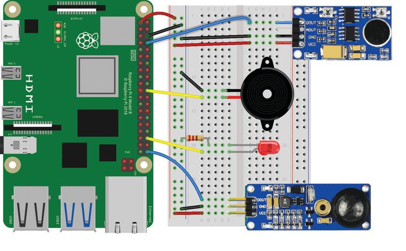
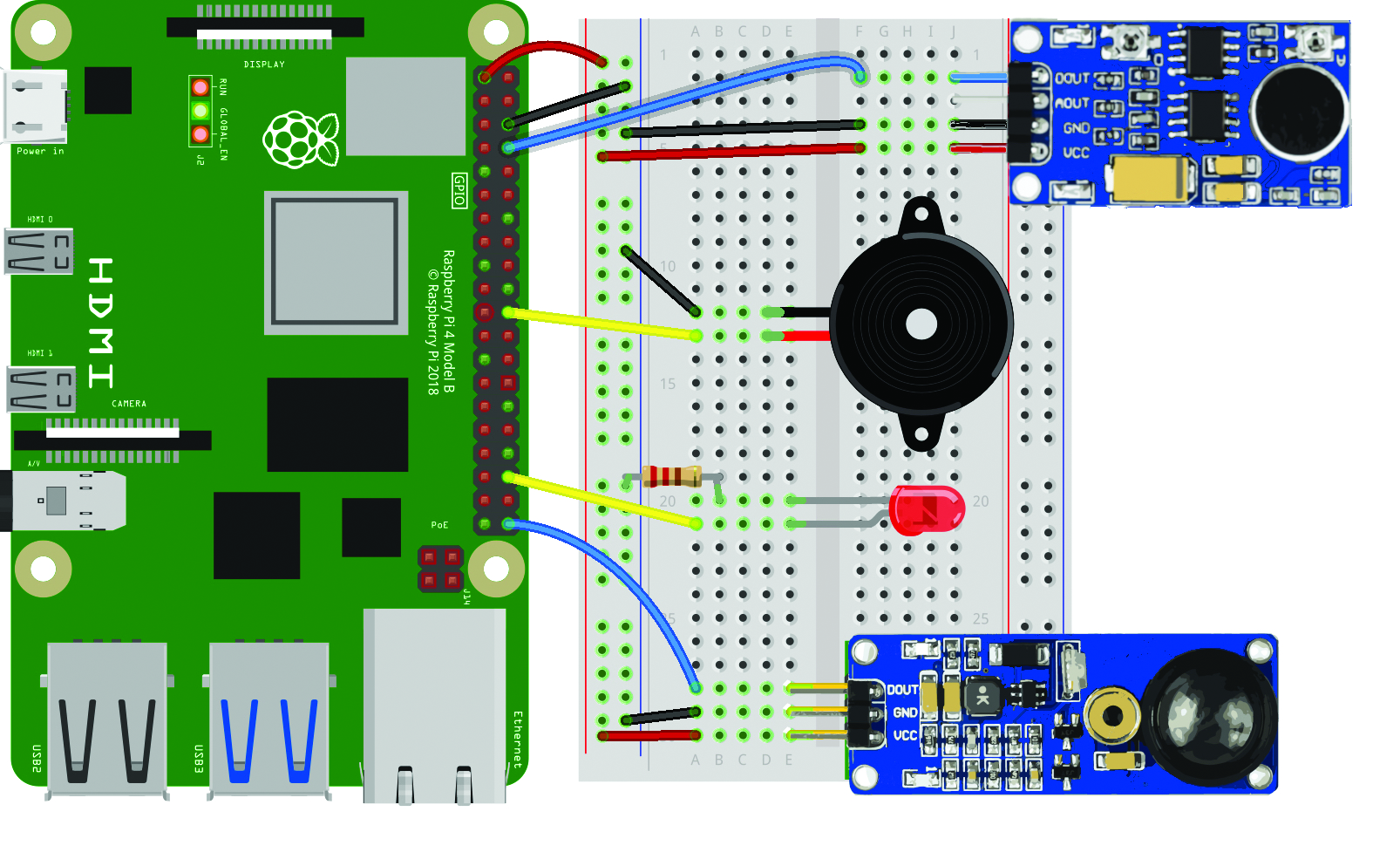
With the power turned off, connect the laser sensor to Raspberry Pi as in Figure 1. We’re powering it from Raspberry Pi’s 3V3 pin, grounding it with a GND pin (both via the breadboard side rails), and the digital output (marked DOUT on the sensor) is going to GPIO 21.
Warning!
The laser sensor used here continually emits a laser beam. Be very careful not to point it towards anyone’s head as it could potentially damage their eyesight.
More information on laser safety.
Laser positioning
With the laser sensor wired up, turn on Raspberry Pi. You should see the sensor’s red power LED (on the right) light up if it’s connected correctly. It should also be emitting a laser beam from the metal tube, so be careful never to look straight into it.
Aim the beam at a nearby wall (up to 1.5 m away) and check that its left LED (marked DAT) is lit, confirming that it is detecting the laser beam. You may need to adjust the vertical and horizontal tilt of the sensor, or move it closer to the wall.For the finished alarm, we recommend you place the laser sensor fairly near the floor so that anyone walking through it will break the beam and it won’t be anywhere near their eyes.
Laser test
To begin, we’ll create a simple Python program, as in the laser_test.py listing, to read the sensor’s digital output and print out a message to show when the beam is broken. From the desktop menu, go to Programming and open the Thonny IDE to start coding.
from gpiozero import Button laser = Button(21)
msg = "" while True: if laser.value == 0: msg = "Intruder!" else: msg = "All clear" print(msg, end = "\r")
As before, we’re using the GPIO Zero library; at the top of the code, we import the Button method from it. We’ll use this to sense when the digital output from the sensor is high, in effect the equivalent of a push-button being pressed. As it’s connected to GPIO 21, we assign the laser object to this with laser = Button(21).
In an infinite while True: loop, we check whether the pin is low (if laser.value == 0), which means the beam has been broken, and set the message (msg1 variable) that we’ll be printing to the Shell area accordingly. In our print statement, we add the end = „\r“ parameter so the message is always printed on the same line.
Run the laser_test.py code and then try breaking the beam with your hand and see if the message changes to ‘Intruder!’. You may find that it works better with your hand more distant from the sensor. Even if the DAT LED only flickers off momentarily, that should be enough to trigger our alarm later.
Add a sound sensor
Now that we have our laser sensor working, let’s make our setup even more intruder-proof by adding a sound sensor. We’re using a Waveshare sound sensor for this, as featured in the Sensors Pack, but other similar sensors are available, along with USB mics.
Our sensor has pins for analogue and digital outputs, but we only need the digital output for our alarm. With the power turned off, we connect that pin (DOUT) to GPIO 14, and the VCC and GNC pins to 3V3 and GND (shared with the laser sensor via the breadboard side rails), as in Figure 1.
Turning Raspberry Pi back on, you’ll see the power LED on the left of the sound sensor is lit up. Make a loud noise and you should see the LED on the right light up to show it has been detected.
Sound test
Let’s create a similar program to test the sensor. In the sound_test.py code listing, we assign the sound object to GPIO14 with sound = Button(14). Again, we use the Button method to detect when the pin is triggered.
from gpiozero import Button sound = Button(14)
msg = "" while True: if sound.value == 1: msg = "Intruder!" else: msg = "All clear" print(msg, end = "\r")
This time in our while True: loop, we test whether the pin is high (there is a loud enough noise to trigger the sound sensor). As before, this determines which message (in the msg1 variable) is printed to the Shell area.
Make a noise
Now it’s time to test our sound sensor to check it’s wired up and working correctly. Run the sound_test.py Python code and then made a loud noise to make the DAT LED on the right of the sensor light up. You may find that you need to be noisy for a second or so and that there’s a short delay before the message changes briefly from ‘All clear’ to ‘Intruder!’.
If you’re having trouble triggering it, try altering the sensitivity of the sound sensor by adjusting the lower potentiometer screw (marked D for digital) on it: turning it anticlockwise increases the sensitivity, but don’t overdo it or the DAT LED will be lit up constantly.
Add a visual alert
If your sensors and code are working correctly, it’s time to move on to the next part. Printed messages are all very well, but for a proper alarm you need a visual and/or audible alert.
As in last month’s guide, we’ll add a standard red LED for a visual alert. Ours is 5 mm, but you can use a different size. As always, a resistor is needed to limit the current to the LED to ensure it doesn’t receive too much and potentially burn out. With the LED placed in the breadboard, with legs in different unconnected rows, we connect a 330 Ω resistor between the negative (shorter) leg and the ground rail of the breadboard. The positive (bent, longer) leg is connected to GPIO 16 on Raspberry Pi, as in the Figure 1 wiring diagram.
Sound the alarm
For our audible alert, we’ll use a small active piezo buzzer to make a beeping noise. You could use something else to sound the alarm. The buzzer has a longer positive leg and a shorter negative one; their positions may also be marked on its top. Connect the negative pin to the breadboard’s ground rail and the positive pin to GPIO 25 (as in Figure 1).
Alarm code
With everything wired up as in Figure 1, you’re now ready to program your intruder alarm. In the final code, intruder_alarm.py, we add LED and Buzzer to the gpiozero imports at the top. We also import sleep from the time library, to use as a delay.
from gpiozero import Button, LED, Buzzer
from time import sleep laser = Button(21)
sound = Button(14)
led = LED(16)
buzzer = Buzzer(25) def alarm(): print("Intruder alert!", end = "\r") for i in range(10): led.toggle() buzzer.toggle() sleep(0.5) while True: if laser.value == 0 or sound.value == 1: alarm() else: print("All clear ", end = "\r") led.off() buzzer.off()
If you wanted, you could create a separate function with a different message for each alarm (like our fire and gas alarm last issue), but this time we’ve kept it simple with a single alarm function, as we’re not bothered how an intruder is detected. When triggered, this executes a for loop which toggles the LED and buzzer on and off a set number of times, with a 0.5 sleep delay each time.
In a while True: loop, we check the pin values from both sensors and trigger the alarm when the laser beam is broken (laser.value == 0) or the sound threshold is exceeded (sound.value == 1). If neither is triggered, we show the default message and ensure the LED and buzzer are turned off.
Test the alarm
Now to test the alarm system. As before, try breaking the laser beam: the LED should then blink and the buzzer will beep. Do the same for the sound sensor by making a prolonged loud noise; the alarm will trigger again. Each time, the ‘Intruder!’ message will show in the Shell area.
Taking it further
We now have a simple intruder alarm. To improve it, you could add extra sensors such as a PIR or even a camera to detect movement. You could trigger a larger light and/or play an alert sound or spoken message on a connected speaker. You could also send an email or push notification alert to your phone whenever the alarm is triggered.
Next time we’ll create a weather station using temperature, humidity, and ultraviolet light sensors. See you then.