Schlagwort: tutorial

  • DIY Fairy House That I Made From Trash

    DIY Fairy House That I Made From Trash

    Reading Time: 3 minutes

    Hi, in this tutorial I show you how I made a fairy house lamp recycling some cardboard from an old box, egg cartons, pizza boxes, toilet paper tubes and two plastic bottles.

    The only bought materials I used are the acrylic colors, the hot glue and the P.V.A. glue (less than 3$ in total). It took me about ten days to finish, including the drying time. Let me know what you think!

    More info: youtube.com

    After cutting the bottom of a bottle, I glued a piece of cardboard to it like this

    By gluing old magazines to the bottle, I made the “foundation” of the house

    I also used old egg cartons to make it sturdier

    When the foundation is ready, it’s time to move further

    Creating a carcass of the house using some cardboards and old pizza boxes

    Making sure everything is stable

    Gluing another bottle to the side of the house

    This will be our little cell!

    Taking care of the windows

    Then, I poured some hot water onto the egg boxes and mixed everything together with PVA glue

    I carefully applied the mass I’ve got onto the entire house

    It should look something like this

    Adding the final touches

    Making the stairs…

    …and the roof

    Last but not least – painting everything!

    Ta-da!

    This is how the finished DIY fairy house looks like

    You can see the entire process in the video below:

    Website: LINK

  • Raspberry Pi LEGO DIY NES Case

    Raspberry Pi LEGO DIY NES Case

    Reading Time: < 1 minute

    We found some nice tutorial on a German website, for your own DIY LEGO Pi Case!!

    The Original Article was way before and also a case to buy, here’s the article: https://www.raspberrypi.org/blog/lego-nespi-case/

    Buy it here: http://www.raspipc.es/public/home/index.php?ver=tienda&accion=verArticulo&idProducto=1305?setLocale=en_GB

    And here is the Tutorial for you own Case, made with LEGO Digital Designer:

    Download: pi-modell

    Download: lego-nes-case-instruction


    Source: https://www.andrerinas.de/tutorials/nespi-like-lego-nes-case-anleitunginstruction.html

    http://ldd.lego.com/de-de/

  • PiBoy3 – Selfmade Arcade Gaming Handheld for under 120$ – TUTORIAL

    PiBoy3 – Selfmade Arcade Gaming Handheld for under 120$ – TUTORIAL

    Reading Time: 4 minutes

    First of all a Happy New Year to all our Community here on blogdot.tv and on our Social Channels 🙂

    We are back in the new year with a quick made tutorial for everyone who wanted to make a game boy by your self ^^ so let’s start…

    THIS TUTORIAL IS BASED ON GETTING THE TFT TOUCH SCREEN WORKING WITH FULL HW SUPPORT / 60FPS AND OPENGL SUPPORT!!!  THIS IS NOT A DESIGN TUTORIAL…


    Parts List:

    37€ – Raspberry Pi 3 (better take a 3, with built in wifi and bluetooth) https://www.cyberport.at/raspberry-pi-3-modell-b-1-gb-1123-00G_544.html 

    33€ – TFT Screen for Pi (we took the Waveshare32, 3.2 Inch Toch Screen, inlc. 3 GPIO Buttons) https://www.conrad.at/de/raspberry-pi-display-modul-schwarz-rb-tft32-v2-raspberry-pi-a-b-b-raspberry-pi-1380381.html

    10€ – 16 GB Micro SD Card (Take a fast one) https://www.conrad.at/de/microsdhc-karte-16-gb-sandisk-ultra-android-mit-80-mbs-und-sandisk-memory-zone-android-app-class-10-uhs-i-inkl-sd-adapter-inkl-android-software-1381008.html

    15€ – 6.000 mAh Battery Pack with overvoltage surge (you need one with at least 2.0A output!!!) https://www.conrad.at/de/powerbank-zusatzakku-varta-powerpack-family-6000-li-ion-6000-mah-1424864.html 

    15€ – Speakers (those are the most problem because of the size, we found some old passive speakers from our old nokia mobile phone that we are using right now) these here are good to open easy https://www.amazon.de/dp/B01MYU3780?psc=1

    10€ – Speaker Alternative: https://www.conrad.at/de/raspberry-pi-erweiterungs-platine-blau-sbc-soundmodule-raspberry-pi-raspberry-pi-2-b-raspberry-pi-3-b-raspberry-pi-a-raspberry-pi-b-raspberry-pi-1503744.html

    10€ – SNES Retro Usb Controller (you can choose the style we took an old one , laying around ) https://www.amazon.de/CSL-Gamepad-Controller-Notebook-Retro-Design/dp/B00HFQEFTY/ref=sr_1_2?ie=UTF8&qid=1484006798&sr=8-2&keywords=snes%2Busb%2Bcontroller&th=1


    SW List:

    Retropie Image: https://retropie.org.uk/download/ we used retropie 4.1 in our tutorial

    TFT Screen Driver: http://www.produktinfo.conrad.com/datenblaetter/1300000-1399999/001380381-an-01-de-8_13_CM__3_2__TOUCH_DISPLAY_320X240_PX.pdf


    Installing Retropie

    Download the Raspberry Pi Image from the Link above, and flash it with ETCHER (Win/Unix/Osx) https://etcher.io/ to your 16 GB SD Card.

    This will take a while….


    When finished , let’s get to the assembling 🙂


    Assembling the PiBoy3

    This is a nice funny video from Element 14 how to use the raspberry pi 3 cases with the pi, and also how to hock up all the cables, we really like it…


    We just need the part to understand how to assemble the case, and also only for those people that never had a Raspberry pi in their own hands by now.


    First Run:

    Your Pi Setup with retropie hocked up to a screen and everythingyou can start you raspberry pi 3.

    First it will resize your image on its own, so you don’t need to do it.

    Second part is emulationstation where it wants to configure a controller, if your controller is hocked up you can set it up, or you can cancel it and leave it for later.

    we gonna leave emulation station, you gonna do that with ‚ctrl‘  +  ‚alt‘ F4 this should open a new terminal where you should be loged in automaticaly, if not the user is ‚pi‘ and the password: ‚raspberry‘

    now we can update the pi for our tft screen to work!

    Installing the TFT Screen


    first we gonna edit the config.txt

    sudo nano /boot/config.txt


    add at the end of the line:


    dtparam=spi=on
    dtoverlay=waveshare32b:rotate=270  

    (THIS IS ONLY FOR THE WAVESHARE TFT DISPLAYS)

    after this edit, let’s restart so the screen turns from white to black that’s good 🙂

    back in emulationstation go straight into the only menu entrance retropie and choose retropie-setup

    A new windows will open there u must choose Configuration/Tools and ‚raspiantools‘

    You will enter a new windows with the option to install Pixel Desktop. DO IT!! 🙂

    Wait a few minutes to finish everything and return back to emulationstation. Restart your Raspberry Pi.

    Again in emulationstation, enter the second terminal like we did above.

    now we need to edit the desktop entries for the tft screen, sudo nano /usr/share/X11/xorg.conf.d/99-calibration.conf

    just copy paste everything and save it with ‚ctrl + o‘   and exit with ‚ctrl + x‘

    Section "InputClass" 
    
    Identifier "calibration" 
    
    MatchProduct "ADS7846 Touchscreen" 
    
    Option "Calibration" "160 3723 3896 181" 
    
    Option "SwapAxes" "1" 
    
    EndSection

    and edit also the file sudo nano /usr/share/X11/xorg.conf.d/99-fbturbo.conf

    change the file from:

    Option "fbdev" "/dev/fb0"

    to:

    Option "fbdev" "/dev/fb1"


    Driver Download:

    cd /tmp 
    
    wget http://www.joy-it.net/anleitungen/rpi/tft32b/waveshare32b-overlay.dtb 
    
    sudo cp waveshare32b-overlay.dtb /boot/overlays/waveshare32b.dtbo

    Reboot your Pi, and you should have your tft screen working with touch screen support 🙂 🙂


    Now let’s get to the picki part Frames and Performance:


    Performance:

    Edit the file sudo nano /boot/config.txt

    paste everything at the end of the file:

    arm_freq=1100
     gpu_mem=333
     force_turbo=1
     core_freq=250
     disable_splash=1
     boot_delay=1

    and comment out the three lines for the gpu memory setting:

    #gpu_mem_256=128
     #gpu_mem_512=256
     #gpu_mem_1024=256

    Now we have our Performance set to get the most games running and also to have a stable environment for the os.

    WE ARE NOT RESPONSIBLE FOR ANY OVERCLOCKING DAMAGE!!!


    After our first Versions we realized, that the Design part will take a little bit longer…

    MKI

    MKII

    Happy New Year 2017 to all our gaming Community and tech Lovers.. Thank you all for the Support!! 🙂 🙂

    Ein von BLOGDOTTV | #GAMES #LIFESTYLE (@blogdottv) gepostetes Foto am

    MKIII


    MKIV Design after 10 Days searching for the right box ^^


    MKV next Design, 3D Printed from https://www.3dhubs.com/

    we callculated a nice case for 25€ with pick up, so that is pretty ok 🙂

    http://www.thingiverse.com/thing:629873


    Hitting the 60 Frames – comming tommorow

    Setting up the GPIO Buttons  – comming tommorow


    Our old Retropie Tutorials:

    https://www.blogdot.tv/2014/08/17/raspberry-pi-retropie-2014-tutorial-make-gaming-console-100/

    *OUTDATED*

    https://www.blogdot.tv/2014/08/23/retropie-emulationstation-steam-xbmc-raspbian-os-fully-working-files-included/

    *OUTDATED*

  • Play Silent Hills: P.T. on PC in VR with Google Cardboard! Full Tutorial iPhone/Android

    Play Silent Hills: P.T. on PC in VR with Google Cardboard! Full Tutorial iPhone/Android

    Reading Time: 2 minutes

    Another Tutorial from us the team behind #blogdottv 🙂

    So we gonna start right away with the Turorial for P.T. the PC Version , also known as PuniTy – PT hallway recreation!

    v2fVK1

    You will need:

    • PC (i5, 8gbram and a solid graphics should do the work)
    • Silent Hill P.T. PC version (remade free download of the console Demo version)
    • Smartphone (capable playing VR content)
    • Cardboard or VR headset (GearVR works to, you need more 3rd Party software for this – Package Disabler Gear VR)
    • Controlls (we recommend a gamepad, xbox controller , etc.)
    • Trinus VR (Android/iPhone App for Streaming PC content to cardboard, vr headset)
    • Time 🙂 🙂


    Download Links: 

    PC

    PuniTy – PT hallway recreationDownload

    Trinus VR ServerDownload

    optional: TriDef 3DDownload (14 Day Trial) VideoLink

    SMARTPHONE

    Trinus VR App – Android/iPhone


    So, you have installed Trinus VR on your PC and phone. Now what?

    Below you will find general instructions on how to create a streaming session between you PC and your smartphone using Trinus VR.

    KEY POINTS

    Before we start, it is important to keep these in mind:

    • Always run your game windowed. If the game doesn’t have such option you can try using DxWnd
    • USB Tethering gives the best performance, but requires tethering to be enabled and working (i.e. Windows to recognize the phone). Refer to your phone manual for details on how to set it up.
    • Disable mobile data while tethered, Windows may try to use the phone as internet access point .
    • For online/multiplayer sessions you will need to change Windows network priorities. Click here for instructions on how to do this.
    • Make sure there are no network blocks between PC and phone (e.g. firewalls)
    • If the screen stays blank/frozen, use the ‘Video Compatible’ mode (remember to window the game). This mode is slower, so consider reducing game resolution to keep a good frame rate and low latency.

    The Lens Settings should be good at the beginning with default, you can always play around with the settings in trinus vr to find your best fits: http://trinusvr.com/help/setup-guide/


    After Setup everything:

    • Turn on Trinus VR Smartphone App
    • Insert Smartphone into Cardboard/VR headset
    • Start Trinus VR PC server application
    • connect Gamepad if not connected (optional)
    • start PuniTy – PT hallway recreation
    • optional Audio setup: headset connected to PC, set default audio output settings do headset
    • enjoy playing , with your selfmade vr headset bringing Silent Hill P.T. Demo back to life on PC  🙂 🙂 🙂

    We hope you liked our small and fast tutorial for playing PuniTy on your VR headset with gamepad or keyboard, you can play also other games with this method, and also as mentioned with real3d support due to the optional 3rd party software!!!

    Gameplay screens


    Source: https://jedlondo.itch.io/punity

    https://www.tridef.com/


  • Discover Pokémon in the Real World with Pokémon GO! Mobile App Startet heute! Pokemon GO PLUS Alle Infos!

    Discover Pokémon in the Real World with Pokémon GO! Mobile App Startet heute! Pokemon GO PLUS Alle Infos!

    Reading Time: 5 minutes

    Get ready for an all-new Pokémon experience! Pokémon GO opens a universe of Pokémon to find, catch, trade, and battle on your iPhone or Android device! With Pokémon GO, you’ll discover Pokémon in a whole new world—your own! Pokémon GO will use real location information to allow players to experience catching, trading, and battling Pokémon. Visit our site for more information.


    Pokémon GO

    Travel between the real world and the virtual world of Pokémon with Pokémon GO for iPhone and Android devices. With Pokémon GO, you’ll discover Pokémon in a whole new world—your own! Pokémon GO is built on Niantic’s Real World Gaming Platform and will use real locations to encourage players to search far and wide in the real world to discover Pokémon. Pokémon GO will allow players to find and catch more than a hundred different Pokémon as they explore their surroundings.

    The Pokémon video game series has used real-world locations such as the Hokkaido and Kanto regions of Japan, New York, and Paris as inspiration for the fantasy settings in which its games take place. Now the real world will be the setting!

    Get on your feet and step outside to find and catch wild Pokémon. Explore cities and towns around where you live and even around the globe to capture as many Pokémon as you can. As you move around, your smartphone will vibrate to let you know you’re near a Pokémon. Once you’ve encountered a Pokémon, take aim on your smartphone’s touch screen and throw a Poké Ball to catch it. Be careful when you try to catch it, or it might run away! Also look for PokéStops located at interesting places, such as public art installations, historical markers, and monuments, where you can collect more Poké Balls and other items.

    Customize Your Trainer

    When you first play Pokémon GO, you’ll get to customize the look of your Trainer, choosing apparel and accessories to give him or her a cool look. Your customized character will appear as you move around on the map, as well as on your profile page. Plus, other players will see your character when they visit a Gym you control.

    Add to Your Pokédex

    In Pokémon GO, you will gain levels as a Trainer, and at higher levels you will be able to catch more powerful Pokémon to complete your Pokédex. You’ll also have access to more powerful items, such as Great Balls, to give you a better shot at catching Pokémon. Keep exploring and encountering Pokémon to raise your level!

    There are other ways to add Pokémon to your roster, too. If you catch the same species of Pokémon enough times, you’ll get the opportunity to evolve one of them. And as you explore, you may find Pokémon Eggs at PokéStops, which will hatch after you’ve walked a certain distance. When they hatch, you may find Pokémon you’ve never seen before!

    Some wild Pokémon will appear only in certain places near where you live or around the world. For example, some Water-type Pokémon may appear only near lakes and oceans. If you’re away from home, be sure to stay alert for Pokémon you wouldn’t normally encounter!

    If you catch the same species of Pokémon enough times, you can evolve one of them. This is useful for catching Pokémon you’re having a tough time finding in the wild. For example, if there are large numbers of Poliwag in your area, but no Poliwhirl nearby, catch a lot of Poliwag to eventually gain the ability to have one of them evolve into a Poliwhirl!

    Join a Team and Battle

    At a certain point in the game, you’ll be asked to join one of three teams. Once you join a team, you’ll gain the ability to assign Pokémon you’ve caught to empty Gym locations or to a location where a team member has placed one of his or her Pokémon. Like PokéStops, Gyms can be found at real locations in the world. Each player can place only one Pokémon at a particular Gym, so you’re encouraged to work with others on the team to build up a strong defense.

    If a Gym is already claimed by another team, you can challenge that Gym using your own Pokémon. Using the Pokémon you’ve caught, engage in battle with the defending Pokémon at the Gym. Battles are challenging and fun. Use your Pokémon’s two attacks to battle the defending Pokémon. You can also dodge the defending Pokémon’s attacks by swiping left and right. If your Pokémon wins the battle, then the Gym’s Prestige is reduced. When the Gym’s Prestige is reduced to zero, the defending team loses control of the Gym, and you or another player can then take control of it by assigning a Pokémon to it. Once your team has control of the Gym, you can increase its Prestige (and level) by training your Pokémon with the defending Pokémon. As the Gym gets to a higher level, your team has the ability to assign more Pokémon to defend it. You can also team up with your friends and battle at a rival Gym together to take down stronger Gyms faster.

    A wide variety of challenges are available that highlight many different categories, such as catching Pokémon and exploration. By completing these challenges, you’ll unlock achievement medals that will appear in your player profile. Try your best to unlock as many medals as you can!

    Pokémon GO Plus

    A portable device called the Pokémon GO Plus will enable Pokémon GO players to enjoy the game even while they’re not looking at their smartphones. The device connects to a smartphone via Bluetooth and notifies the player about events in the game—such as the appearance of a Pokémon nearby—using an LED and vibration. In addition, players can catch Pokémon or perform other simple actions by pressing the button on the device. Look forward to the launch of the Pokémon GO Plus accessory in late July 2016.

    inline-576x240

    Free to Play

    Pokémon GO will be available for download at no charge on the App Store and Google Play. Pokémon GO is free to play, with loads of fun things to do and Pokémon to discover at every turn. For players who want to enhance their Pokémon GO experience even more, certain items and features can be accessed via in-app purchases. Players can spend real money on PokéCoins, the in-game currency of Pokémon GO. PokéCoins can then be exchanged for power-ups, extra items, and other enhancements.

    An early field test limited to the United States, Japan, Australia, and New Zealand is under way for Pokémon GO while the game is still in active development. The features, available languages, design, and overall appearance are not final. Please stay tuned for information about expansion of the field test to other markets.

    Download: http://www.blogdot.tv/2016/07/06/pokemon-go-download-link-mirror-android-apk/


    Photo Fun

    When you encounter a Pokémon in the wild, you can turn on the camera feature, putting the wild Pokémon into the live scene where your camera is facing. Then, capture the moment with the in-game camera you can find in your Bag. Line up your shot and hit the shutter button to take the photo. The pic will then be saved to your phone’s photos for you to share however you’d like.

    Music by Junichi Masuda

    Pokémon GO will feature all-new music composed by GAME FREAK’s Junichi Masuda. Mr. Masuda has worked on Pokémon games since the very beginning and has composed many of the classic and memorable songs that have inspired fans for decades.

    Stay tuned to Pokemon.com for more information about Pokémon GO!

    © 2016 Niantic, Inc. © 2016 Pokémon. © 1995-2016 Nintendo / Creatures Inc./ GameFreak, Inc.


    Official site: http://www.pokemon.com
    Facebook: http://www.facebook.com/Pokemon
    Twitter: http://www.twitter.com/Pokemon
    Instagram: http://www.instagram.com/Pokemon

  • PS4 RemotePlay Tutorial Windows7/8/8.1/10 – Mac OSX ElCapitan

    PS4 RemotePlay Tutorial Windows7/8/8.1/10 – Mac OSX ElCapitan

    Reading Time: < 1 minute

    [mbYTPlayer url=“https://www.youtube.com/watch?v=xr-bpK7_Mbo“ opacity=“.5″ quality=“medium“ ratio=“auto“ isinline=“false“ showcontrols=“false“ realfullscreen=“true“ printurl=“true“ autoplay=“true“ mute=“true“ loop=“true“ addraster=“true“ stopmovieonblur=“false“ gaTrack=“false“]

    PS4 RemotePlay Tutorial Windows7/8/8.1/10 – Mac OSX ElCapitan

  • Geek 3D Prints Super Game Pi, a Fully-Functional Portable Gaming Console!

    Geek 3D Prints Super Game Pi, a Fully-Functional Portable Gaming Console!

    Reading Time: 3 minutes

    3D printing can be used to make many things, including portable gaming consoles, like the Super Game Pi. This DIY game console has 12 buttons, an analog joystick, stereo speakers and a 5-inch HDMI display. This geek used a Raspberry Pi A+ and RetroPie image to enable users to play lots of games across several platforms.

    [mbYTPlayer url=“https://www.youtube.com/watch?v=f_zp42fQ-dQ“ opacity=“.5″ quality=“medium“ ratio=“auto“ isinline=“false“ showcontrols=“false“ realfullscreen=“true“ printurl=“true“ autoplay=“true“ mute=“true“ loop=“true“ addraster=“true“ stopmovieonblur=“false“ gaTrack=“false“]

    [sublimevideo settings=“youtube-id:f_zp42fQ-dQ“ width=“651″ height=“366″]

    Features Components:
    • Raspberry Pi A+
    • True 5” HDMI Display w/ TFP401 Display Driver
    • Analoy joystick + 6 Buttons
    • 66000mAh Lithium Ion Battery
    • Powerboost500 Charger
    • Stereo Audio
    —————————————-­-

    super-game-pi-portable-game-system

    Download 3D Print Case: super-game-pi Source: https://www.youmagine.com/designs/super-game-pi

    Circuit Analysis

    Take a moment to look over the components. The circuit diagram is ment to be used a reference for visualizing wired connections.

    The length of wires, dimension of components, and positions are not exact.

    gaming_circuit-diagram.png

    Wired Connections

    The four main components (Raspberry Pi A+, TFP401 display driver, 2.8W Amplifier and PowerBoost500C) will be powered by the PowerBoost 500C and a 6600mAh Lithium Ion battery via JST cable. To power the circuit on/off, a slide switch is connected to the EN, GND, and Bat pins on the PowerBoost500C.

    The 2.8W Amplifier is connected to GND and +Postive pins on the PowerBoost 500C. A right-angle 3.5mm stereo plug to pigtail cable is wired to the amp and connected to the audio jack on the Pi A+. Two mini metal speakers are wired to the audio output pins on the amp.

    The 5V and GND pins on TFP401 display driver are wired to the 5V and GND pins on the PowerBoost500C. A flat HDMI cable is connnected from the TFP401 to the Raspberry Pi A+.

    The 5″ HDMI display uses a 40-pin FPC extension board to connect the TFP401 display driver to the screen.

    Raspberry Pi GPIO

    Below is a legend of each connection. It includes the pin number, name and connection. The GPIO graphic matches the order of the pins. Use this to reference which buttons connect to the GPIO.

    gaming_pin-legend.png

    How Do I Read This?

    The pin# is the actual number of the pin in series. The numbers go from left to right, top to bottom. The name is the title for a given pin entity. Note the GPIO # does not match the pin number. The connection is the button or wire that needs to be assoicated with the pin.

    The GPIO # will be associated with the Input value in the retrogame.c file.

    In most cases, you should print out the legend (on physical paper) and use it as a cheatsheet while assembling the circuit.

    Button ConnectionsUP        – GPIO 17, Pin 11
    DOWN – GPIO 27, Pin 13
    LEFT    – GPIO 22, Pin 15
    RIGHT  – GPIO 23, Pin 16
    Select  – GPIO 18, Pin 12
    Start    – GPIO 4, Pin 07
    A         – GPIO 24, Pin 18
    B         – GPIO 10, Pin 19
    X         – GPIO 09, Pin 21
    Y         – GPIO 25, Pin 22
    L         – GPIO 11, Pin 23
    R         – GPIO 08, Pin 24
    Color CodesBlack    – Ground
    Red       – DC Power
    Blue      – SDA1, I2C
    Green   – GPIO
    Orange – TX/RX
    Pink       – SPI
    Yellow  – I2C ID EEPROM


    „To make your own Super Game Pi, you’ll have to 3D print the enclosure, hack an SNES controller and solder electronics. You can pick the Raspberry Pi A+ and all the parts to build this project from Adafruit. We’ll need some hand tools and access to a 3D Printer,“ says its creator.

    Source: https://learn.adafruit.com/super-game-pi

  • We present, Paper Shooters Assault Rifle! Perfect for Office Wars.

    We present, Paper Shooters Assault Rifle! Perfect for Office Wars.

    Reading Time: < 1 minute

    Here’s a first: a cardboard assault rifle designed to look like a weapon straight from the Call Of Duty world. Available in 3 different models – Digital Ops, Zombie Slayer, and the limited edition Golden Touch – these paper gadgets fire biodegradable pellets up to 75-feet. They’re packaged in true DIY kit form, where you get to assemble each and every part of the gun. Since each gun is loaded with water soaked paper pellets that have been placed in shell casings, you simply clip the magazine cartridge into the gun and fire away.

    [mbYTPlayer url=“https://www.youtube.com/watch?v=-JtZziT_fqc“ opacity=“.5″ quality=“medium“ ratio=“auto“ isinline=“false“ showcontrols=“false“ realfullscreen=“true“ printurl=“true“ autoplay=“true“ mute=“true“ loop=“true“ addraster=“true“ stopmovieonblur=“false“ gaTrack=“false“]

    paper-shooters-assault-rifle

    http://www.papershooters.com/

  • How to use QUMOX SJ4000 (SJCAM) with official GoPRO Studio Software!

    How to use QUMOX SJ4000 (SJCAM) with official GoPRO Studio Software!

    Reading Time: 2 minutes

    Hey everyone, we got a Video earlier this Week from a Qumox SJ4000:

    We got many Questions about the Cam, and here some Details to make everything clear:
    Original Manufactur and Name: SJCAM
    Amazon Model Name: QUMOX
    we found out that QUMOX has no official Website, no Manufactur or something else,  but the cam is the Original Parts and SW as of the SJCAM, very interesting!
    So here’s the Tutorial Part for all:
    And a lill bit of patience 😉
    So first of all Extract the actual MpegStreamClip zip to a Folder you want, and Start the Program. You Should see a screen like this:
    mpegstreamclip1
    Just select File, Open, Select your QUMOX or SJCAM Footage, and choose ‚Export to MPEG4‘
    You can define your Settings you want, the Best is for GPStudio just to go to 100% Quality and Save it as a New Mpeg4 File!
    After a little bit of wait , the file should be ready and converted and you can go on to GoPro Studio to Open your New Converted File:
    32860_1_gopro_releases_studio_2_0_makes_editing_video_easier_than_ever
    In the GoPro Studio App make sure to Check out the Free Templates you can Download and Use 🙂 😉
  • Philips PicoPix PPX 3614 Android Beamer + How to install XBMC Frodo + Autostart

    Philips PicoPix PPX 3614 Android Beamer + How to install XBMC Frodo + Autostart

    Reading Time: 2 minutes

    Hey everyone, we got the PicoPix Beamer from Philips Picopix last week as a review item. We are very impressed by the way so tinny and so big Screen!

    So here’s the Tutorial for the Philips PicoPix PPX 3614 (Android 2.3.1) to install the XBMC Media Center onto the device. (so you got a small workaround for apps like spotimc or other xbmc apps)

    PPX3614_EU-RTP-global-001


    The Pico Pix Beamer comes with an installed APK Installer, and also Preinstalled Apps like YouTube and more.

    (mehr …)

  • Remote Play on PS4 and PS Vita – Step by Step Guide + Use a Vita as a second PS4 controller

    Remote Play on PS4 and PS Vita – Step by Step Guide + Use a Vita as a second PS4 controller

    Reading Time: 2 minutes

    Maybe you’re picking up a PlayStation 4 today (and you should, because it’s a pretty damned cool console), and one of the games you happen to pick up supports 2 player’s on screen at the same time. Maybe you don’t have a second controller, but your buddy, wife, girlfriend, dog, brother or sister wants to get in on some two-player action. If you have a Vita, you’re sorted.

    Friends

    To quote:

    Sony has released a simple Step by Step guide for those looking to use Remote Play via their PlayStation Vita and PlayStation 4.

    The tutorial is rather brief, but is easy to follow and walks users through basic the process of getting the service up and running between the two pieces of hardware.

    Remote Play on PS4 and PS Vita – Step by Step Guide

    Pairing your PS4 and your PS Vita for Remote Play is quick and easy – and you’ll only have to do it once for the two systems to stay connected.

    As you know, you can use Remote Play to beam the game that’s playing on the PS4 to a PlayStation Vita. One problem with that is that it has to be the same PSN account on the Vita as the PS4. Not really too much of an issue, though. Just use remote play (make sure you’re connecting the vita to the Ps4 directly) and take over the session. Then, with the controller, sign in as a guest or secondary profile.

    Aaaaand Bob’s your uncle. The Vita can be used as one controller, while the actual controller functions as player two. I played a whole lot of LEGO: Marvel yesterday with a friend doing this, and as long as the Vita was connected directly, it worked a treat. Response, for a game like Marvel, worked perfectly. Other games at launch that’ll work this way include Knack, and Call of Duty: Ghosts. And probably a few sports titles.

    There are some things you’ll have to get used to, like using the rear-touchpad on the Vita as the L2, L3, R2 and R3 buttons, but it’s a good temporary solution until you can pick up another controller. You’ll also forgo any sort of rumble on the Vita.

    It’s a bit obvious, really – but If you’ve just blown your cash on a PS4 and don’t have the cash for a second controller at the moment, but you have a Vita gathering dust in your cupboard, put it to some good use.

    Official Source: http://www.youtube.com/watch?v=fX9BLNIm7Fc

    http://www.lazygamer.net/general-news/use-a-vita-as-a-second-ps4-controller/

  • Tutorial how to use PS4 remote play away from home with PS Vita

    Tutorial how to use PS4 remote play away from home with PS Vita

    Reading Time: 5 minutes

    So here we found some interresting articles on Sony Forums Website:

    Registering a device

    The first time you use  
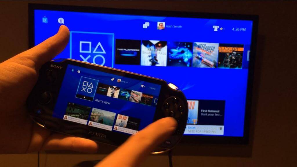
(PS4 Link), you must register (pair) a PS4™ system with your system.
    The number of PS4™ systems you can register with your system is limited.

    • You can register 1 PS4™ system with your system for remote play.
    • You can register up to 10 PS4™ systems with your system to use the second screen feature. If you try to register any additional PS4™ systems with your system for use with the second screen feature, the information of the PS4™ system that you have not connected to for the longest time will be automatically deleted.

    Registering (pairing) a device

    Connect your system and the PS4™ system directly using Wi-Fi, or connect them through a wireless access point to register a device.

    Before performing these procedures, you need to do the following:

    • Link the PS4™ system and your system to the same Sony Entertainment Network account.
      If you have an account that was created on a different device, such as a PS3™ system or a computer, you can sign in using that account.
    • If you are connecting the systems directly using Wi-Fi, select  (Settings) > [PS Vita Connection Settings] from the PS4™ system’s function screen, and then select the [Connect Directly with PS Vita] checkbox to set a checkmark.
      • If you are connecting the systems using a wireless access point, the systems must be connected to the same network.

    3

    1.
    On the PS4™ system’s function screen, select  (Settings) > [PS Vita Connection Settings] > [Add Device].
    A number appears on the screen.
    2.
    On your system, select  (PS4 Link) > [Start], and then select [Remote Play] or [Second Screen].
    3.
    Enter the number displayed on the PS4™ system’s screen, and then select [Register].
    When registration is complete, the PS4™ system’s screen is displayed on your system.

    After these steps you should be able to see this:

    1451502_10200240040282535_1225221367_n


    https://www.facebook.com/photo.php?fbid=10200240040282535&set=a.1442666445510.52293.1798575725&type=1

    So now we get ready to connect outside 😉

    Playing remotely

    To use remote play via the Internet from outside your home, you must first prepare the PS4™ and PS Vita systems.

    • When using an access point provided by a commercial or public Wi-Fi service, or by a private wireless network, set up your system so that it can connect to that access point .
    • Turn on the PS4™ system.
      • On the PS4™ system’s function screen , select  (Settings) > [PSNSM] > [Activate as Your Primary PS4] > [Activate].

    On your system, select  (PS4 Link) > [Start] > [Remote Play]. When the devices connect successfully, the PS4™ system screen appears on your system.

    • On the PS4™ system’s function screen, you must select  (Settings) > [PS Vita Connection Settings], and then select the [Enable Remote Play] checkbox to set a checkmark.
    • If you enable remote start on the PS4™ system, you can use remote play to wake the PS4™ system from standby mode. On the PS4™system’s function screen, select  (Settings) > [Power Save Settings] > [Set Functions Available in Standby Mode], and then select both [Connect to the Internet] and [Enable Turning On PS4 from Network] to set checkmarks.
    • In some network environments, the remote play connection might become unstable.

    Using remote play via the Internet

    You may not be able to use remote play via the Internet depending on your network connection. If this occurs, the following reference information might help you make a connection.

    • On the PS4™ system’s function screen, select  (Settings) > [Network] > [Test Internet Connection], and then confirm that you are able to connect to both the Internet and PSNSM.
    • If your router supports UPnP, enable it on the router.
    • If your router does not support UPnP, you must adjust the router’s port forwarding setting to allow communication to the PS4™ system from the Internet. The port numbers that are used by remote play are 9295 (for TCP), and 9296 and 9297 (for UDP). If these ports are unavailable, it might be possible to use ports 9295~9304 (for TCP and UDP). For information about these settings, refer to the instructions supplied with your router.
    • If the PS4™ system is connected to the Internet via two or more routers, communication may not work correctly.
    • A router is a device that allows multiple devices to share a single Internet line.
      Communication might be restricted depending on the security functions provided by your router or Internet service provider. Refer to the instructions supplied with the network device in use, and information from your Internet service provider.
    • Port forwarding is a function for forwarding signals that arrive at a specific port (entrance) to another specified port (exit). This is also referred to as „port mapping“ or „address conversion.“

    As we found a hint from user greggumz on reddit:

    He got many problems while connecting, but managed to do it 😉

    We found out while we were reading all the manuals and his post, when you disable the ‚Connect Directly with PS Vita‘ checkbox

    3


    Than you don’t need to go out or something to test it in your enviorment, so the AD-HOC mode from PS4 is turned off 😉

    And ‚STREAMING‘ Mode is not working while you are using Remote Play!

    Hope this helps someone, post problems and toughts.


    Official Source: http://manuals.playstation.net/document/en/psvita/ps4link/device.html

    http://manuals.playstation.net/document/en/psvita/ps4link/viainternet.html

    http://www.reddit.com/r/PS4/comments/1rkt0u/if_you_got_ps4_and_vita_remote_play_to_work_via/

  • Make yourself the Most Useless Machine EVER! Tutorial Instructions

    Make yourself the Most Useless Machine EVER! Tutorial Instructions

    Reading Time: 10 minutes

    Also Known As: The Ultimate Machine

    Parts list

    Battery Pack
    Gear Motor
    Toggle Switch
    Microswitch
    Printed Circuit Board
    Green & Red 3 mm LEDs
    Two 56 Ohm Resistors
    Hook-Up Wire
    Heat Shrink

    Soldering The Machine:

    Soldering is so easy there’s a comic book instruction guide called Soldering is Easy that we recommend.  It was created by DIY guru Mitch Altman, Andie Nordgren & Jeff Keyzer.

    If you have never soldered before we highly recommend that you read the above and/or get help from someone with experience before you assemble our kit.

    Observe All Safety Precautions:  wear eye protection.  Don’t breath the fumes: work in a well ventilated area.  Do not touch the hot end of the soldering iron…

    Tip:  Helping Hands  In the above photo you’ll see various ways of holding parts steady in order to solder them.  A PanaVise on the left is a great tool to own if you solder on a regular basis.

    Do not go out and buy a PanaVise just for this project. Less expensive alligator-clip contraptions are available or you can macgyver one as shown in the above photo using pliers and a rubber band.

    We don’t recommend using your real hand…

    PCB Top & Bottom

    Most of the components will be mounted on the Top-Side of the printed circuit board, with the exception of the LEDs.  Make sure you read the entire instructions before starting.

    Step 1:Seat Toggle

    Insert the toggle switch into the top-side of the circuit board as shown in the photo.  

    It’s location is marked on the circuit board as “Toggle”.


    Soldering Toggle

    On the bottom side of the board, solder all 6 pins of the toggle switch.


    Step 2:Insert Resistors

    Insert the two resistors in locations R1 & R2 as shown in the photo.

    Bend the wire leads of the resistors outward to help keep them in place while you solder them to the board.

    Solder the Resistors

    Solder the resistors to the board.

    Clip off the excess leads using a pair of snippers, nippers or even finger-nail clippers.


    Step 3:Insert the LEDs

    The green and red LEDs (LightEmitting Diodes) look identical so we’ve marked the wire leads of thered LED with ared felt marker in order to differentiate them.

    Insert the green LED in the location marked LED1.  The longer lead is the positive (+) one and should be inserted in the hole nearest the + symbol marked on the board.

    The red LED goes in the LED2 location and the longer positive lead goes in the hole nearest the + symbol.

    LED Detail

    The green LED needs to stand off the board 2 millimeters as shown in the photo.

    The red LED should be flush with the board.

    Bend the wire leads of the LEDs outwards so they stay in place while you solder them from the top side of the board.


    Bend Green LED

    After soldering, carefully bend the green led as shown in the photo and then clip the excess leads from the LEDs.


    Step 4:

    Cut the hook-up wire into two pairs about 17 cm (6.5 inch) and 10 cm (4 inch) long.


    Step 5:Microswitch

    Split one end of shorter, 10cm pair of wires and strip back 1/2cm of insulation.

    Cut the heat-shrink in two and slip them over the end of the wires as shown in the photo.  Make sure you keep the shrink away from the ends when are soldering; you don’t want to prematurely shrink them.

    Solder the wires to the outside pins on the micro-switch.  The middle pin on the micro-switch is not used.

    Now move the heat-shrink tubing over the end of the wires, and carefully apply heat using a heat gun or lighter.

    Step 6:Microswitch to PCB

    Split/strip the other end of the micro-switch wires and route them through the strain-relief holes. Solder the wires to the pads labeled Micro as shown in the photo.

    Polarity does not matter, either wire can go in either pad.

    Step 7:Battery Leads

    The battery holder comes with its wire leads stripped and tinned.

    Route the leads from the battery holder through the strain-relief holes of the board ensuring that the red wire goes to the Bat+ location & the black wire to theBat- location.

    Note: polarity matters, make sure the red and black wires are soldered to the correct pads.


    Step 8:  Split/strip the ends of the 17cm hook-up wire pair.

    You’ll note that the conductors are copper and silver colored which helps us install the motor wires with the correct polarity.Motor Wiring

    As shown in the photo to the right, solder one end of the silver wire to the indicated pin on the motor.

    The other end of the silver wire is soldered to pad on the board labeled Mot-.

    Solder the copper colored wire to the the other tab on the motor.  It’s other end is soldered to the Mot+ pad on the circuit board.

    Note that the wires are routed through the strain-relief holes in the board as well as through the clear plastic strap on the end of the motor.

    Test The Circuit:

    The above photos show how the circuit operates.

    ▪ When the toggle switch is flipped ON, the red LED is on and the motor turns counter-clockwise.

    ▪ When the toggle switch is flipped OFF, the green LED is on and the motor turns clockwise.

    ▪ Depressing the micro switch shuts power off to the whole circuit only when the toggle switch is in the OFF position.

    PART2:

    Step 1:
    Remove the protective film covering the acrylic pieces. The film protects the pieces from getting scratched during shipping.

    Step 2:Attach Motor
    Use a #1 Phillips screwdriver to attach the motor to the motor-mount bracket using the two longest screws.

    Tip: Be careful that the motor wires do not become pinched between the motor and the acrylic bracket, causing a finger alignment problem later.

    Step 3:Attach Micro-switch

    Attach the micro-switch using two of the smaller screws.

    Make sure you install the micro-switch so the bump on the micro-switch lever is at the top, as show in the photo to the right.

    Step 4:
    Attach the finger to the cam disc using two small screws.


    Make sure the protruding bump on the cam is assembled as shown in the photo.

    Step 5:Attach Finger
    Mount the finger and cam assembly to the motor shaft using the last small screw.

    You may need to depress the lever on the micro-switch in order to clear the bump on the cam.


    Step 6.
    Understand how the mechanism works:

    When the toggle is pointing to the left (the OFF position), then the green LED is lit and the motor turns clockwise until the micro-switch is activated by the cam, cutting off power to the machine.

    When you switch the toggle to the right (the ON position), then the micro-switch is bypassed, the red LED lights up, and the motor turns counterclockwise.


    The arrow in the picture indicates where the bump on the cam is depressing the micro-switch lever.

    When the toggle is in the OFF position and the micro-switch is depressed, then the machine should be powered off completely; there should be no power, no lights, and no motor movement.

    Step 7.
    Test your assembled mechanism:

    With the toggle switch in the OFF position, put two AA batteries in the holder. The finger should turn clock-wise until the cam touches the micro-switch. The micro-switch is wired so that when pressed, the switch is open (or off), opposite from way most push buttons work. The green LED should then turn off.

    Flip the toggle briefly to the ON position, and then back to the OFF position.

    Warning: Be careful as the machine is not fully assembled so, if the toggle is left in the ON position too long, the motor will keep turning counterclockwise until the finger hits the micro-switch in the other direction.

    You will want to flip the toggle back to the OFF position quickly.

    If the motor turns in the wrong direction, then you have either installed the motor backwards or the batteries are in backwards.

    Remove the batteries before proceeding to the next step.

    Step 8:
    Place a nut it the T-Slot on the motor bracket, as indicated by the arrow in the photo.

    Tip: You can use a small piece of tape to hold the nut temporarily in place.

    Carefully place the top cover plate on the tabs on the top of the motor mount bracket.

    Step 9:
    Carefully insert a bolt into the hole on the top plate. Thread the bolt into the nut and tighten it.

    Notice: Two rectangles were laser-etched into the top plate on the other side of the center hole. Do not try to remove or punch out these rectangles as they are cosmetic and meant to balance the appearance of the real tabs of the motor mount bracket.

    Drop a bolt into the hole between the rectangles and secure it from beneath with a nut.

    Note: The protective blue film on the finger in these two photos is only to make the finger easier to see in the photo. You should have removed the protective film from all your acrylic pieces in the first step for assembly.

    Step 10:
    The toggle switch has 2 hex nuts, a flanged washer, and a knurled lock washer.

    Remove all of them and replace the knurled lock washer.

    Insert the toggle switch into the center hole of the top plate with the LED’s facing the finger.

    Thread one of the hex nuts onto the toggle switch and carefully tighten with a 5-16″ socket or pliers.

    Warning: Be careful not to scratch the acrylic while tightening the nut.

    Now you can insert batteries and fully test the mechanism. The top plate should be a working Ultimate Useless Machine Assembly.

    Remove batteries before proceeding to the next step.

    Case Assembly

    Step 11:
    Start assembling the case:

    Attach the lid as shown in the photo. If you prefer having a blank ‘mystery’ box without “The Ultimate Useless Machine” text showing, then flip the top plate over and assemble the plate with the writing down.
    Note: Pay attention to the orientation of the hinge plate. If you install the hinge with the wrong side facing out, you will have trouble fitting the lid into the case and the lid will not move freely.

    Step 12:
    Attach the sides of the case.

    Note: Make sure the engraved lines on the front and side plates face out.


    Step 13:
    Leave out the final two nuts and bolts on the last side plate, and leave the other nuts loose in the plate, until you can slip the hinged end plate into the pivot holes on the side plates.

    Then press the side plate into position and install the last two nuts and bolts.

    Tighten the other nuts and bolts.

    Step 14:
    To keep the battery holder from moving around in the case, cut the velcro strip in two and apply the hooks side of the velcro to the bottom of battery holder.

    Stick the fuzzy sides of the velcro to the corresponding locations inside the case. Position the battery holder away from the acrylic finger, along the right side.


    Step 15:
    Lower the Toggle Plate Assembly into position on the top of the case and bolt it in place.


    Step 16:
    Stick the rubber feet onto the bottom of the machine. You are done!

    Official Source: http://frivolousengineering.com/

    http://www.youtube.com/watch?v=mD8BHWygt1c

    http://frivolousengineering.com/?page_id=4394#sthash.liRuwUo5.dpuf