Geek 3D Prints Super Game Pi, a Fully-Functional Portable Gaming Console!
> INITIATING DECRYPTION SEQUENCE...
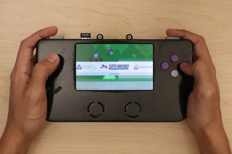
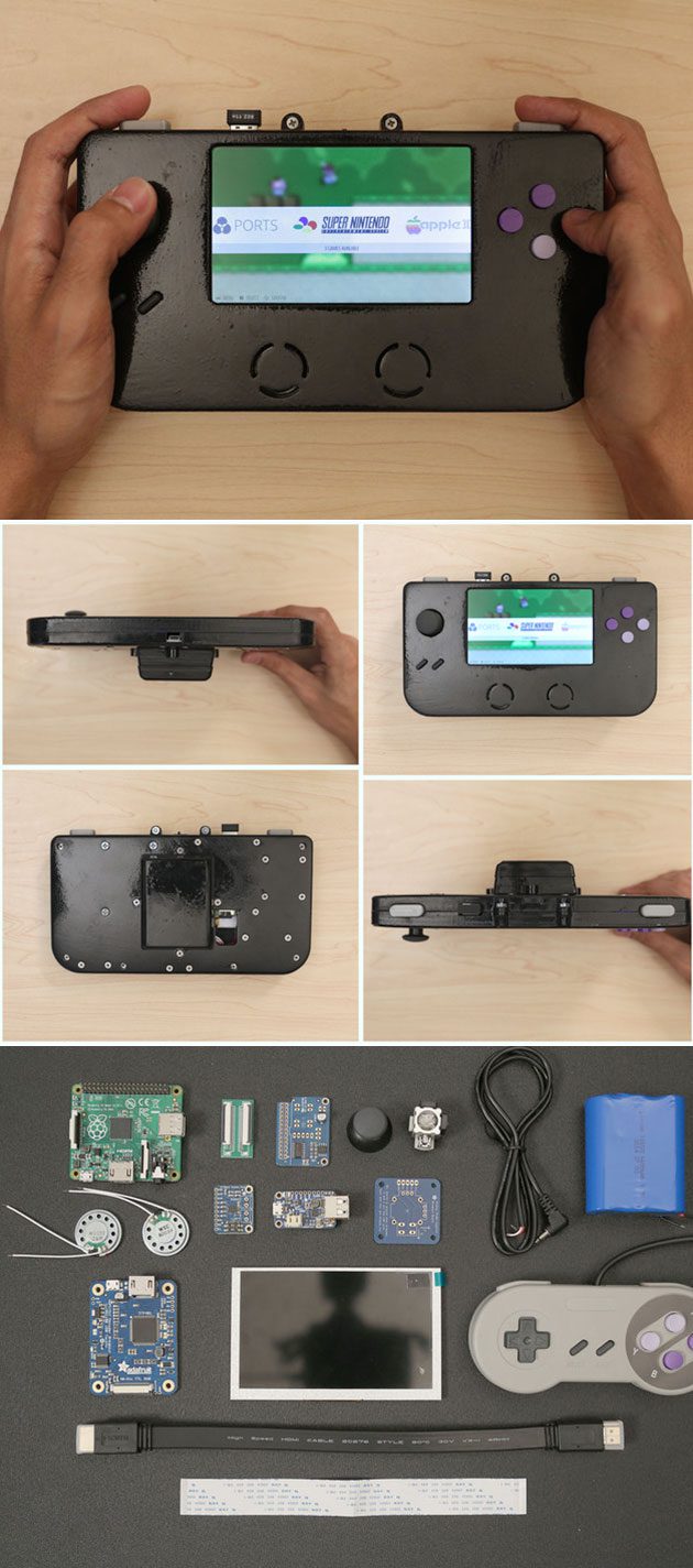
3D printing can be used to make many things, including portable gaming consoles, like the Super Game Pi. This DIY game console has 12 buttons, an analog joystick, stereo speakers and a 5-inch HDMI display. This geek used a Raspberry Pi A+ and RetroPie image to enable users to play lots of games across several platforms.
[mbYTPlayer url=”https://www.youtube.com/watch?v=f_zp42fQ-dQ” opacity=”.5″ quality=”medium” ratio=”auto” isinline=”false” showcontrols=”false” realfullscreen=”true” printurl=”true” autoplay=”true” mute=”true” loop=”true” addraster=”true” stopmovieonblur=”false” gaTrack=”false”]
[sublimevideo settings=”youtube-id:f_zp42fQ-dQ” width=”651″ height=”366″]
Features Components:
• Raspberry Pi A+
• True 5” HDMI Display w/ TFP401 Display Driver
• Analoy joystick + 6 Buttons
• 66000mAh Lithium Ion Battery
• Powerboost500 Charger
• Stereo Audio
—————————————-
Download 3D Print Case: super-game-pi Source: https://www.youmagine.com/designs/super-game-pi
Circuit Analysis
Take a moment to look over the components. The circuit diagram is ment to be used a reference for visualizing wired connections.
The length of wires, dimension of components, and positions are not exact.

Wired Connections
The four main components (Raspberry Pi A+, TFP401 display driver, 2.8W Amplifier and PowerBoost500C) will be powered by the PowerBoost 500C and a 6600mAh Lithium Ion battery via JST cable. To power the circuit on/off, a slide switch is connected to the EN, GND, and Bat pins on the PowerBoost500C.
The 2.8W Amplifier is connected to GND and +Postive pins on the PowerBoost 500C. A right-angle 3.5mm stereo plug to pigtail cable is wired to the amp and connected to the audio jack on the Pi A+. Two mini metal speakers are wired to the audio output pins on the amp.
The 5V and GND pins on TFP401 display driver are wired to the 5V and GND pins on the PowerBoost500C. A flat HDMI cable is connnected from the TFP401 to the Raspberry Pi A+.
The 5″ HDMI display uses a 40-pin FPC extension board to connect the TFP401 display driver to the screen.
Raspberry Pi GPIO
Below is a legend of each connection. It includes the pin number, name and connection. The GPIO graphic matches the order of the pins. Use this to reference which buttons connect to the GPIO.

How Do I Read This?
The pin# is the actual number of the pin in series. The numbers go from left to right, top to bottom. The name is the title for a given pin entity. Note the GPIO # does not match the pin number. The connection is the button or wire that needs to be assoicated with the pin.
The GPIO # will be associated with the Input value in the retrogame.c file.
In most cases, you should print out the legend (on physical paper) and use it as a cheatsheet while assembling the circuit.
| Button ConnectionsUP – GPIO 17, Pin 11 DOWN – GPIO 27, Pin 13 LEFT – GPIO 22, Pin 15 RIGHT – GPIO 23, Pin 16 Select – GPIO 18, Pin 12 Start – GPIO 4, Pin 07 A – GPIO 24, Pin 18 B – GPIO 10, Pin 19 X – GPIO 09, Pin 21 Y – GPIO 25, Pin 22 L – GPIO 11, Pin 23 R – GPIO 08, Pin 24 |
Color CodesBlack – Ground Red – DC Power Blue – SDA1, I2C Green – GPIO Orange – TX/RX Pink – SPI Yellow – I2C ID EEPROM |
“To make your own Super Game Pi, you’ll have to 3D print the enclosure, hack an SNES controller and solder electronics. You can pick the Raspberry Pi A+ and all the parts to build this project from Adafruit. We’ll need some hand tools and access to a 3D Printer,” says its creator.
Source: https://learn.adafruit.com/super-game-pi