Schlagwort: raspberrypi

  • Make a 3D camera

    Make a 3D camera

    Reading Time: 6 minutes

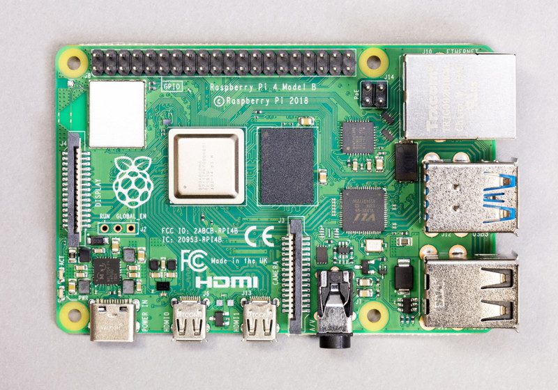
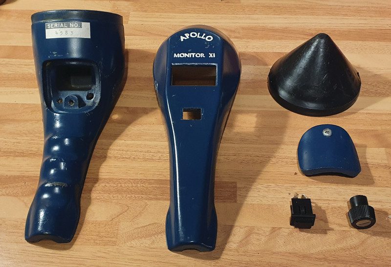
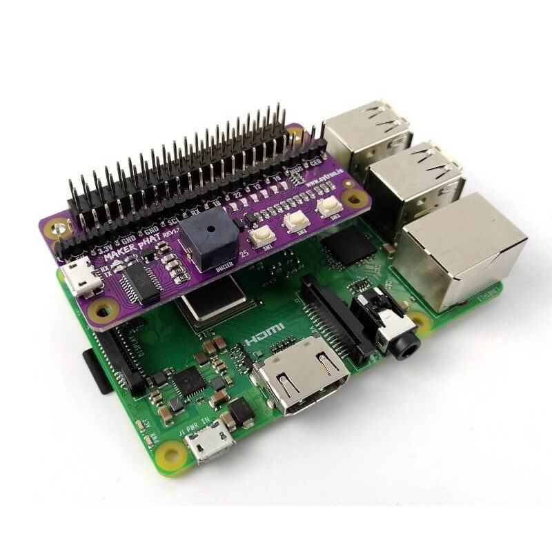
    Kit you’ll need to build a 3D camera

    Here’s an example of what can be produced. This is a cross-view image, so, if you can, cross your eyes together until they settle on a central image. Don’t strain if your eyes feel tired!

    Prepare Raspberry Pi

    To create 3D photographs, we need to be able to take two photos simultaneously, about 5 cm apart. These images can then be processed into a variety of different formats such as parallel view, cross-view, or anaglyph (when you wear red/green glasses). As this is a 3D project, it’s not surprising to learn that we’ll need two of everything. As we can only attach one camera per Raspberry Pi Zero W, we’ll need to prepare a left and right computer. Start by installing Raspbian Lite as normal on both computers and updating everything with:

    sudo apt update && sudo apt full-upgrade

    Make sure both computers are connected to WiFi before proceeding.

    Know the difference

    Choose one computer for the left camera and the other for the right. From the command line, run sudo raspi-config and go to Networking Options > Hostname. Change the name from ‘raspberrypi’ to ‘leftcam’ and ‘rightcam’ on each respective Raspberry Pi Zero. Also in raspi-config, make sure SSH is enabled on each (Preferences > Interfaces).

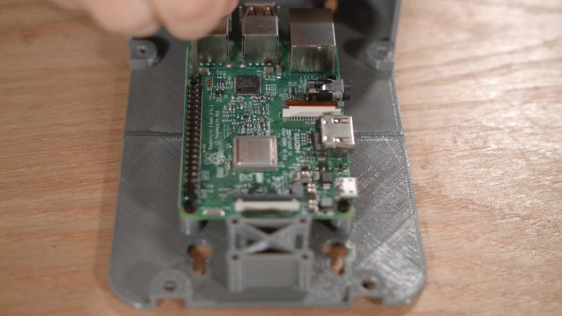
    After this, leave the configuration utility and shut both computers down. Now is a very good time to attach the short camera cable that was supplied with the case to each Raspberry Pi Zero and thread it through the slot on the rear of the case and insert both computers. Add the cover and label each case as ‘left’ or ‘right’.

    Power sharing

    As we have two Raspberry Pi Zero boards, we need two power supplies, right? Well, we can pull a little trick so that only one is required. With some wire, solder a 5 V line and a ground (GND) line from one GPIO to the equivalent on the other (see Figure 1 diagram). This ‘power rail’ allows the second Raspberry Pi Zero W to pull power from the one connected to a USB power supply. Just remember to use a suitable power supply with enough amperes to power both. We found the official micro USB supply worked well. Check, check, and double-check before following this step. Soldering to the wrong connectors could permanently damage your devices.

    Figure 1 Here, a 5 V GPIO pin and GND pin are connected to their equivalents on the other GPIO so one Raspberry Pi Zero W provides power for the other

    Attach the cameras

    It’s really important that the two cameras are lined up together and not at odd angles. We’ve provided a STL file for 3D-printing a mounting plate that holds them perfectly in place. You don’t have to use it, but if you do have access to a 3D printer, it’ll make life easier. Connect the short ribbon cables provided with the cases to each camera, then attach the cameras to the mounting plate side-by-side using the nuts and bolts. Be very careful not to bend or tear the ribbon cables. Finally, flip the cameras over so the plate is resting on the case lids and affix them with some sticky pads.

    So we’re not troubled by multiple power supplies, we can power one Raspberry Pi Zero from the other

    Camera testing

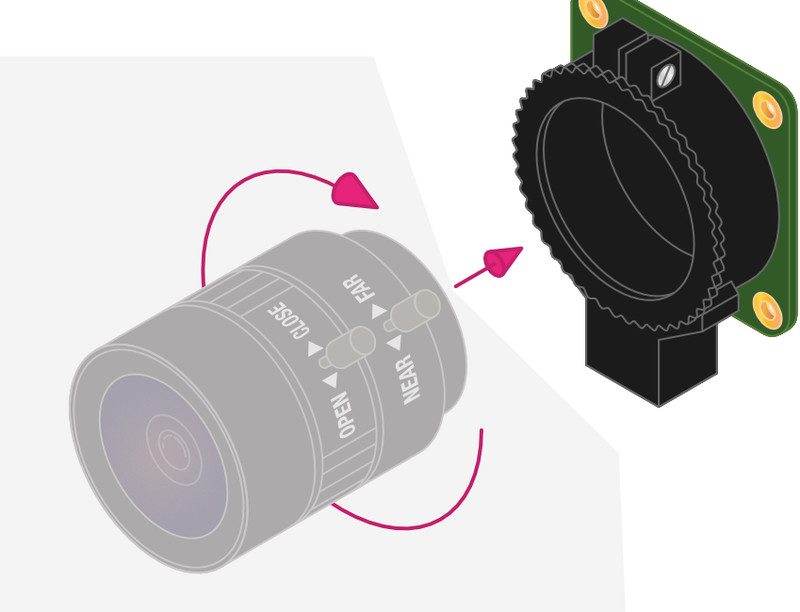
    Before going any further, test that both cameras are working as expected. Carefully attach the lenses to each camera board (if you’re using the mounting plate, watch out for the control levers hitting each other). Use SSH to log in remotely to your left camera (ssh pi@leftcam.local) and at the command line, enter this:

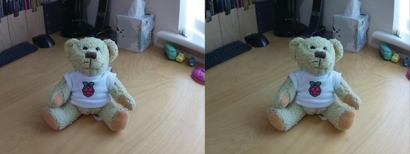
    raspistill -o test.jpg 

    After a few seconds, an image file will be created in your current directory. Transfer it back to your computer and have a look. Chances are it’ll be blurry – but so long as an image was taken, we’re all good. Repeat this test on the right-hand camera.

    Streaming for two

    If you’ve been wondering how one camera is going to get its image to the other, the answer is by setting up a HTTP-based stream on each camera. This will turn each Raspberry Pi Zero W into a streaming webcam and we can then view both images from a further website we’ll install later. The following steps need to be followed on each Raspberry Pi Zero W. Start by installing some libraries we need:

    sudo apt install cmake libjpeg8-dev git 

    Now we’ll get and build the MJPEG streaming software:

    git clone https://github.com/jacksonliam/mjpg-streamer.git cd mjpeg-streamer/mjpeg-streamer-experimental make sudo make install
    

    First test images

    To run the package we’ve just installed, enter the following commands on each Raspberry Pi Zero W: cd ~/mjpeg-streamer/mjpeg-streamer-experimental export LD_LIBRARY_PATH=. ./mjpg_streamer -o „output_http.so -w ./www“ -i „input_raspicam.so“ There is now a web server running on each device. Have a look by visiting

    http://leftcam.local:8080/ 

    and

    http://rightcam.local:8080/.

    Each will have a fun little website where you can view static and video feeds from each camera. When you’re done, you can stop each server by entering CTRL+C in the Terminal.

    Bring them together

    To view both images on the same page and generate 3D images, we need a further web service that takes a feed from both sites we’ve just installed. Create a directory called 3dcamera in your home directory, then create two files: 3dcamera.py and control.html.

    Enter both code listings (or download them from GutHub) and save. This is a very simple web server and an HTML page that will display both images on a single page and, with a simple click, create and download a parallel-eye image.

    Make sure both MJPEG streamers are running and then start the additional server on leftcam only:

    python3 3dcamera.py
    

    You should be able to access the site at

    http://leftcam.local:8081/ 

    and be able to see a video stream of each device.

    View your image

    Take an image by holding the cameras steady and clicking ‘Snap!’ on the website. The dual image will be downloaded to your computer. If you have a Google Cardboard kit or one of the widely available mobile phone VR headsets, transfer your parallel image to your mobile phone and then view it in glorious three dimensions. If not, many people can see the image by focusing their eyes ‘beyond’ the two images until they merge into one. If you’re struggling with this, reverse the two captured images as noted in the code to create a cross-view image.

    Take it further

    This is just a starting point for your adventures in 3D photography. We haven’t touched on creating anaglyphs or streaming 3D video. Check out the GitHub repo for a more advanced version that allows you to set the type of image to generate and adds a few more features. What’s the most creative thing you can do with your 3D camera?

    3dcamera.py

    import os
    import urllib.request
    from http.server import SimpleHTTPRequestHandler, HTTPServer
    from PIL import Image
    from io import BytesIO port = 8081
    control_html = os.path.dirname(os.path.realpath(
    __file__)) + '/control.html'
    # Reverse the URLs to create cross-view images instead of parallel
    left_camera = "http://leftcam.local:8080/?action=snapshot"
    right_camera = "http://rightcam.local:8080/?action=snapshot" def process_image(): left_image = urllib.request.urlopen(left_camera) right_image = urllib.request.urlopen(right_camera) images = [Image.open(x) for x in [left_image, right_image]] widths, heights = zip(*(i.size for i in images)) total_width = sum(widths) max_height = max(heights) side_by_side_image = Image.new('RGB', (
    total_width, max_height)) x_offset = 0 for image in images: side_by_side_image.paste(image, (x_offset, 0)) x_offset += image.size[0] image_buffer = BytesIO() side_by_side_image.save(image_buffer, format='JPEG') image_data = image_buffer.getvalue() return image_data class handle_request(SimpleHTTPRequestHandler): def do_GET(self): print('Sending control HTML') f = open(control_html, 'rb') self.send_response(200) self.send_header('Content-type', 'text/html') self.end_headers() self.copyfile(f, self.wfile) def do_POST(self): new_image = process_image() self.send_response(200) self.send_header('Content-type', 'image/jpeg') self.send_header('Content-disposition', 'attachment; filename="3d.jpg"') self.end_headers() self.wfile.write(new_image) httpd = HTTPServer(("", port), handle_request)
    try: httpd.serve_forever()
    except KeyboardInterrupt: pass httpd.server_close() 

    control.html

    <!DOCTYPE html>
    <html> <head> <style> .viewfinder { display: flex; } </style> </head> <body> <h1>3D Camera</h1> <div class="viewfinder"> <img src="http://leftcam.local:8080/?action=stream" /> <img src="http://rightcam.local:8080/?action=stream" /> </div> <form method="post" action="/"> <button>Snap!</button> </form> </body>
    </html> 
  • BeeMonitor

    BeeMonitor

    Reading Time: 3 minutes

    “The aim of the project was to put together a system to monitor the health of a bee colony by monitoring the temperature and humidity inside and outside the hive over multiple years,” explains Glyn.

    “Bees need all the help and love they can get at the moment and without them pollinating our plants, we’d struggle to grow crops. They maintain a 34°C core brood temperature (± 0.5°C) even when the ambient temperature drops below freezing. Maintaining this temperature when a brood is present is a key indicator of colony health.”

    An Arduino sends the temperature data to Raspberry Pi via a USB cable

    Wi-Fi not spot

    BeeMonitor has been tracking the hives’ population since 2012 and is one of the earliest examples of a Raspberry Pi project. Glyn built most of the parts for BeeMonitor himself. Open-source software developed for the OpenEnergyMonitor project provides a data-logging and graphing platform that can be viewed online.

    The hives were too far from the house for WiFi to reach, so Glyn used a low-power RF sensor connected to an Arduino which was placed inside the hive to take readings. These were received by a Raspberry Pi connected to the internet.

    At first, there was both a DS18B20 temperature sensor and a DHT22 humidity sensor inside the beehive, along with the Arduino (setup info at magpi.cc/ds18b20sensing). Data from these was saved to an SD card, the obvious drawback being that this didn’t display real-time data readings. In his initial setup, Glyn also had to extract and analyse the CSV data himself. “This was very time-consuming but did result in some interesting data,” he says.

    Unlike the humidity sensor, the bees don’t seem to mind the temperature probe

    Sensor-y overload

    Almost as soon as BeeMonitor was running successfully, Glyn realised he wanted to make the data live on the internet. This would enable him to view live beehive data from anywhere and also allow other people to engage in the data.

    “This is when Raspberry Pi came into its own,” he says. He also decided to drop the DHT22 humidity sensor. “It used a lot of power and the bees didn’t like it – they kept covering the sensor in wax! Oddly, the bees don’t seem to mind the DS218B20 temperature sensor, presumably since it’s a round metal object compared to the plastic grille of the DHT22,” notes Glyn.

    The system has been running for eight years with minimal intervention and is powered by an old car battery and a small solar PV panel. Running costs are negligible: “Raspberry Pi is perfect for getting projects like this up and running quickly and reliably using very little power,” says Glyn. He chose it because of the community behind the hardware. “That was one of Raspberry Pi’s greatest assets and what attracted me to the platform, as well as the competitive price point!” The whole setup cost him about £50.

    Glyn tells us we could set up a basic monitor using Raspberry Pi, a DS28B20 temperature sensor, a battery pack, and a solar panel.

    BeeMonitor complete with solar panel to power it. The Snowdonia bees produce 12 to 15 kg of honey per year

  • Share your keyboard and mouse with Barrier

    Share your keyboard and mouse with Barrier

    Reading Time: 4 minutes

    Download Barrier to Raspberry Pi

    Barrier is used to share a keyboard between Raspberry Pi and other computers: Windows PC, Mac, or Linux (even a second Raspberry Pi).

    We’re going to use Barrier to share a keyboard and mouse connected to our Raspberry Pi to a Windows PC on the same network.

    First, install Barrier on Raspberry Pi using APT. Open a Terminal and enter:

    sudo apt update
    sudo apt install barrier -y

    Install Barrier on the client

    Now download Barrier to your client computer (in our case the Windows PC) from the Barrier GitHub page.

    Open the BarrierSetup-2.3.2.exe program (you may have a later version number). Use the corresponding DMG file for macOS – or APT for a Linux, as shown in the previous step.

    Make sure all of your computers are connected to the same network before going any further.

    Client and server

    Now that Barrier is installed on both computers, you need to decide which one is going to be in control. This is the one you will have your keyboard and mouse connected to. This will be the ‘server’ and the other computer will be the ‘client’.

    Because we use our Raspberry Pi so much, we’re going to connect our keyboard and mouse to it and have it control the secondary Windows PC. But it could easily be the other way around.

    If you’re using a laptop and Raspberry Pi, then it’s probably better to set the laptop as the server (because it will always have a keyboard and mouse attached), and the Raspberry Pi as the client.

    Set up the server

    Barrier is installed on Raspberry OS, and is opened by choosing Menu > Accessories > Barrier. The Barrier window will appear (below).

    The Barrier server configuration running on Raspberry Pi

    Ensure that Server is ticked and make a note of the IP address (on our Raspberry Pi this is 192.168.0.41; on your network the IP address may be different).

    Set up the client

    Now open the Barrier app on your client machine (in our case a Windows 10 computer).

    Deselect the Server checkbox and select Client instead. Enter the IP address for Raspberry Pi into the Server IP text box. On our setup, Raspberry Pi is located at 192.168.0.41 (below). Your IP address may vary – it is displayed in Barrier on Raspberry Pi. Make a note of the screen name for your client computer. Ours is ‘lucyhattersley-dell’.

    Barrier on the Windows PC and is set up in client mode. Here is our server configuration

    Configure server

    Head back to Barrier on Raspberry Pi and click Configure Server. This will open the Server Configuration window (below).

    The Server Configuration window is used to set up the position of both monitors correctly (so the mouse flows from one screen to another)

    Now you need to add, and position, the client computer using the Screen Name. Drag the monitor icon from the top-right of the Server Configuration window and place it next to the monitor icon marked ‘raspberrypi’. Ours is positioned to the left of our Raspberry Pi (to match the monitor layout).

    The monitor icon will be called ‘Unnamed’. Double-click it to open the Screen Settings window and change the Screen Name to match the client computer – for example in our case, ‘lucyhattersley-dell’ (below). Click OK to close the window.

    It is important to use the correct screen name of your computer in the Screen Settings window

    Start it up

    Click Start on Barrier on your server computer (in our case, Raspberry Pi). Wait until the lock icon in the bottom left of the Barrier window displays ‘Barrier is running’.

    Now click Start on Barrier on the client computer (our Windows PC). Again, wait for the ‘Barrier is running’ message.

    Mouse and keyboard

    Move the mouse pointer on your Raspberry Pi over to the left of display and it will flow to the client machine. Now you can use Raspberry Pi’s mouse and keyboard to control the Windows interface. Open an app and click on a text box (such as a web browser and URL box). Now you can use Raspberry Pi’s keyboard to enter text into your Windows computer. It’s now safe to disconnect any keyboard and mouse from the client computer. You’ll be able to use the server keyboard and mouse moving forward.

  • Argon Neo & Argon Fan HAT review

    Argon Neo & Argon Fan HAT review

    Reading Time: 3 minutes

    Alongside the fan, The Argon Fan HAT provides a power button, which can perform safe shutdown, forced shutdown, and reboot Raspberry Pi.

    Putting it together

    As with other cases (such as Flirc), the metal part of the case connects to the CPU and RAM (with included thermal paste). The metal case acts as a passive heatsink.

    A neat touch it shares with Argon One is the GPIO pin layout guide printed on the case. (Although with the Argon Fan HAT attached, half of the GPIO pins numbers are hidden behind the board.)

    Unlike Argon One, you can also access Raspberry Pi’s Display and Camera ports (the latter only without the fan connected). When you’re done with accessing ports and GPIO pins, the metal lid snaps the whole kit shut via a magnet to form a stylish metal case.

    Argon Neo is a stylish case with a lid that can be removed to break out the GPIO pins

    Keeping it cool

    The fan speed is related to the CPU temp, kicking in at 55°C and increasing to 100% fan speed at 65°C.

    We stress-tested a Raspberry Pi 4 (4GB) CPU at full capacity for 15 minutes with both Argon Neo and Argon Fan HAT attached.

    Things started at 37°C and the temperature slowly rose and hovered around 55°C, before the fan duly kicked in and held the temperature in check for the full 15 minutes, maxing out at 58°C.

    We ran the same test with the Argon Neo case without the fan attached and found the temperature maxed out at 58°C – exactly the same temperature as with the fan attached.

    None of this is anywhere close to threatening Raspberry Pi performance. As the CPU temperature approaches 85°C, Raspberry Pi OS throttles the CPU speed to bring down the temperature. Either with or without the fan, we didn’t get anywhere near that temperature.

    The Argon Fan HAT sits on top of Raspberry Pi and provides additional cooling at temperatures above 55°C

    With that in mind, we overclocked our Raspberry Pi 4 to 2.0GHz and reran the test. Without the fan, the temperature ran up to 82°C (and was kept in check by the passive cooling of the case alone). Still not enough for Raspberry Pi OS to begin throttling the CPU.

    So, we are left wondering whether you actually need the fan?

    Which to buy?

    It’s $15 for the Argon Neo case and $10 for the Fan HAT, which makes the package the same price as the larger Argon One.

    To its credit, the Argon Neo is a more minimalist design that’s slimmer and more in keeping with the design aesthetic of Raspberry Pi. It’s certainly a neat solution, and is cheaper if you opt for the Argon Neo case on its own.

    Verdict

    8/10

    We like this an awful lot, but we like the original Argon One case a little more. However, the Neo is stylish and cheaper if you opt for the case without the fan.

  • Coffee Maker Greenhouse

    Coffee Maker Greenhouse

    Reading Time: 3 minutes

    A beans to an end

    Having eventually figured out how to disassemble the original machine, Jeremy then turned his attentions to using its features in a new way. “There’s an air pump that, when activated, causes water (or presumably coffee) to go out the spout,” he says. “It seems that it pressurises the liquid chamber and forces water out this way… As for my setup, the Raspberry Pi activates this air pump at a certain time. The brew button is a manual trigger for watering. A soil moisture sensor tells the system when it’s thirsty (though doesn’t control it directly) – when dry, a red light built into the Keurig (and repurposed) lights up. A blue repurposed light signifies that it’s watering.”

    Ingenious, and such a great way to redeploy something destined for the scrap-heap, but Jeremy admits that there were a few challenges along the way, including figuring out the button and light circuitry from only the wires: “I didn’t disassemble enough to actually see where they were going.”

    He also admits that it does still require some fine-tuning, but he’s generally pretty happy with his new gardening aid. “I left the outer cover off as I think the internals look cool,” he adds, “but I hid all the extra parts in the original electronics cavity inside, so it does look mostly original, if partially disassembled.”

    Inside the Coffee Greenhouse

    Fast Facts! Coffee Maker Greenhouse

    • This project took Jeremy 20–30 hours, over a period of around two months

    • He wrote this article on the build

    • A 3D-printed part houses a Raspberry Pi Zero W inside the machine

    • He also grows pineapples in pots made from disposable juice containers

    • His future project plans include a portable oscilloscope

    One person’s rubbish…

    Jeremy is not done tinkering just yet. “There’s an unused but hooked-up power button that I may do some sort of lighting test with,” he says. “I suppose it is an automatic watering system, but I’ve had the thought that I could put a tube on it and water larger plants. Again, more of a thought, but you could get like ten of these for a giant watering system. In this case, solar power would be good, but would kind of mess up the looks.”

    Jeremy chose to use a Raspberry Pi Zero W because it was the perfect size to fit inside the Keurig’s electronics compartment, along with a mini breadboard. He has used Raspberry Pi computers before, including running his 3D printer via OctoPrint. “I also have a DIY NAS setup that runs on a Raspberry Pi 4,” he adds.

    Online feedback on the watering machine has been positive, says Jeremy. “People seemed to think it was a neat idea when I told them about it before it was quite finished, or at least on the internet. I’ve gotten good feedback from YouTube etc.” Inspired yet? It just shows what you can do with a little imagination… and a Raspberry Pi, of course!

  • Build your own classic games console in The MagPi #95

    Build your own classic games console in The MagPi #95

    Reading Time: 2 minutes

    The Migration Museum

    Migration Museum

    A museum celebrating the diversity of London’s residents comes to life when visitors linger near its artefacts. The Room To Breathe interactive displays are the handiwork of Chris Owens and his colleagues from  Clay Interactive. Just one of the many incredible community projects that use Raspberry Pi to make the world a better place.

    Pi Commander

    Pi Commander

    The 1980s was a golden era for imaginative electronic toys. Adrien Castel has taken a Sky Fighter F-16 game and turned it into a micro Raspberry Pi-powered arcade machine.

    Build a DOS emulation system

    Build a DOS Emulation system

    Use the powerful DOSBox-X emulator to boot Raspberry Pi to DOS and run anything from Windows 3.11 to classic games. The extra oomph of the 4GB or 8GB edition of Raspberry Pi 4 provides plenty of power for emulating classics of the past.

    Helene Virolan interview

    Helene Virolan interview

    Helene Virolan and her daughter Avye Couloute are two incredibly important people in the maker community, making huge steps to help young girls explore an interest in STEM.

    We deliver to your door

    Buy The MagPi magazine issue #95 from the Raspberry Pi Press store and we will deliver it straight to your door. Plus! Take a 12-month subscription in print and we’ll give you a free Raspberry Pi Zero computer and starter kit worth £20.

  • Competition: win one of five 8GB Raspberry Pi 4!

    Competition: win one of five 8GB Raspberry Pi 4!

    Reading Time: < 1 minute

    Subscribe

  • Giant Battleships

    Giant Battleships

    Reading Time: 3 minutes

    Dan Aldred has now taken the concept one stage further by recreating the classic Battleships game on a giant colour LED matrix, with the player issuing shot co‑ordinates using the rotary dial of an old telephone.

    “After creating my giant 10×10 LED board – which is great for light shows, lockdown discos, and general colour displays – I wanted to create a giant game,” he reveals. As he had previously coded his own version of Battleships for the Sense HAT, it seemed a natural choice. In this version, the game is played solo with a limited number of torpedoes to try to sink all the randomly placed ships. After a short introduction, the player is asked to select their first co-ordinate. “You simply dial a number and this is then sent as data to the LED board’s Raspberry Pi, which triggers another prompt telling the player to dial the second number,” explains Dan. “Once the co-ordinates have been dialled in, the board tracks the locations, flashes, and then calculates if the torpedo has hit a boat. If it was successful then a message is sent back to the telephone which triggers a random response consisting of an explosion (sound) and a voice update. If the torpedo misses, different data is sent to the telephone which triggers the miss response, the sound of empty water.”

    Double helping of Raspberry Pi

    While Dan originally intended to use a single Raspberry Pi for the project, he ended up using two of them – one inside the LED matrix and another in the telephone – to avoid the matrix’s NeoPixels interfering with the audio for the sound effects and speech, which is played through the telephone’s original handset speaker. “The simple solution was to use a second Raspberry Pi which would be situated away from the LED [matrix].”

    Two-way communication between the project’s two Raspberry Pi boards is achieved using sockets controlled by Python, although Dan encountered some problems. “I did manage to establish one-way communication between the telephone and the LED board fairly early on in the project but could not get the board to communicate back to the telephone, which meant that I could not trigger the gameplay sounds and updates. Big thanks to Nicole Parrot who showed me that I was using redundant code and sent me an example of the new code and from then on it was plain sailing!”

    The giant LED matrix comprises a 10×10 grid of NeoPixels, their light diffused by jars

    Reading the dial

    The method for how the Raspberry Pi reads the numbers from the phone’s rotary dial is simple, according to Dan. “Basically, you send a small current from a GPIO pin through the rotary dial and back to a GND pin on Raspberry Pi. When you dial a number, the circuit is broken or interrupted (often referred to as clicks). So if you dial a number one, you get one click, or one interruption; if you dial the number seven, you get seven clicks or interruptions.” Bought for just £5, the 1960s Bakelite phone had plenty of room for housing a Raspberry Pi.

    Dan discovered it was made by Swiss manufacturer Zellwegger, which used to make government listening devices and phone tapping equipment. “This is where I got excited that perhaps my Swiss telephone had sat on the desk of an important person and been tapped!” says Dan.

    While a thorough inspection of all the parts of the phone sadly revealed no bugging device, “There is something quite fun about hearing the instructions and game sounds coming through an old telephone handset.”

    The LED matrix doubles as an impressive disco light show. Dan is considering using it for Conway’s Game of Life

  • Smart Doorbell and Video Intercom System

    Smart Doorbell and Video Intercom System

    Reading Time: 3 minutes

    “Not many smart doorbells have a screen for the visitor and I thought creating one would be fun,” explains Aaron Tainter. Deciding that his project could also double as a video intercom system if he produced more than one device, he soon got down to work. He figured the system could connect to a virtual meeting room with the touch of a button and send a notification to a mobile phone, allowing a video connection to be made.

    Aaron is a software engineer who enjoys making hardware projects in his free time and teaching others how to make them through his YouTube channel, Hacker Shack.

    “For this project, I knew that I would need a computer that was small, had input for GPIO pins, could connect to the internet, and could handle video streaming,” he reveals. “A Raspberry Pi seemed like the perfect choice – they’re really easy to build with and they integrate with everything.”

    Avoid putting sensitive data on the doorbell’s Raspberry Pi because it could be compromised by anyone gaining access to the USB port

    Opportunity rings

    Aaron approached the project in his usual way. “I always start by looking at the electronic components needed for the core features and any open-source software projects that might make the project easier to build,” he says.

    “Once I’ve figured out the basic systems design and done some initial experiments with software scripts to verify that the project works, I design a housing to fit around the parts. For this project, the most important feature for me was the audio-video I/O. I had to investigate a few different options for hardware parts to make sure that the audio was good enough for a video call.”

    The smart doorbell’s enclosure was designed using CAD software and it was outputted to a 3D printer. “The most challenging part of this build was finding parts which would all work with the Raspberry Pi for video calls and then getting them to fit inside a small enclosure,” Aaron reveals.

    “Thankfully, I had my mechanical engineering friend help design the 3D printed enclosure, but it took several revisions to get all the components to fit together after being printed. The tolerances on my printer were great, so we had to do quite a bit of sanding and filing to make everything fit together.”

    Before attaching Raspberry Pi to the case, Aaron plugged the mic into a USB port. He then connected the camera and speaker, with solder applied to the power wires

    Hello world

    A momentary button with an LED was fitted along with a Raspberry Pi 3 Model B connected to an LCD screen, camera, USB microphone, and a STEMMA speaker that comes with a plug-and-play amplifier. Then it was on to the coding. “The software for this project was relatively simple,” says Aaron. “It took some experimentation to get all of the electronics configured with the device, but the main script was only a couple of hundred lines.” He repurposed some code from an old Raspberry Pi smart security camera that he built a couple of years ago. He used the free encrypted video conferencing app Jitsi Meet to create the video calls.

    So how well does it work? “The video stream playback was a little choppy on a Raspberry Pi 3 during extended use, but I think it might have been because the video call website that I used sucked up too much CPU,” Aaron reckons. “I haven’t tested it, but a Raspberry Pi 4 might work better. People may also want to try implementing their own webcam server and streaming at a lower resolution to optimise performance.”

    Once everything was fitted, Aaron connected Raspberry Pi over VNC to enable the components and video calling

    See also:

  • Caroline Dunn interview

    Caroline Dunn interview

    Reading Time: 2 minutes

    What was your first Raspberry Pi project?

    I learned about the Raspberry Pi April 2014 during my first project with [it], installing Alexa Voice Service with my friend Steve Youngblood. We saw a tutorial on ‘How to Make an Alexa’ and decided to try it with no prior Raspberry Pi experience. It took us six hours to complete our first Raspberry Pi project. We would work on [it] every day on our lunch hour at work and invite our co-workers in our office to watch and/or help. Mostly they just laughed at us bumbling our way through the project. Morale at work was low and we provided comic relief. Prior to this project, I had not used terminal commands in well over a decade. We documented the entire experience on YouTube.

    What’s been your favourite (Raspberry Pi-related) video to make?

    Wow, that’s a tough question, like picking a favourite child or pet. I like practical projects, ones where there is a usefulness to our everyday lives. The most useful project that I have made and still use today is the motionEye project with motion-triggered photo and video. I initially set it up to monitor my geriatric cat, but after a large fire in my neighbour’s apartment, I use it to monitor anyone coming in and out of my apartment.

    What is your story with The MagPi issue 57?

    When [that issue] came out with the Google AIY kit, I went on a wild goose chase to try to buy [it]. I called every bookstore in my city in an attempt to find the elusive issue 57. One bookstore employee said, “You’re only the sixth person to call with that question today,” before hanging up on me. I was desperate to do the Google AIY project and started researching ways to complete the project without issue 57. I ordered a ‘button’ so that I could do the project, then I became impatient waiting two days for it to arrive. While waiting, I figured out how to do the project without the button and without issue 57. When the button arrived, I completed the project with the button. Approximately a year later, the AIY kits were sold at my local Micro Center, and then I finally completed the original project from issue 57.

    Mental well-being

    „Because I am concerned for the mental well-being of people sheltering at home, I’ve started a weekly live show on my YouTube channel where anyone can ask me questions, and I present project ideas that can be completed at home. I dedicate a section of my show to Raspberry Pi every week. For example, last week I provided the free link to the Code the Classics [book] made possible by Raspberry Pi. Anyone can access my weekly show from my channel page, youtube.com/caroline. My weekly show is broadcast every Thursday, 3pm EST / 8pm GMT.”

  • Apollo Pi

    Apollo Pi

    Reading Time: 3 minutes

    When the gauntlet was first laid down, Martin decided it would be a good time to use an Adafruit thermal sensor he’d already bought. “Our libraries already use commercial thermal visitor counters, so I thought I’d build my own,” he reasoned. Years of designing projects has taught him that it’s best not to get too hung up sticking with your original plans. Instead, he says, it’s best “to get started and see where the project takes you!” He advises: “it’s always good to do lots of research up front and have a clear idea of what you want to achieve, but some of the most rewarding projects are those where you make at least some of it up as you go along.”

    Martin expected it to be a quick build. “I thought I’d pop the components into an old infrared flash gun in an afternoon,” he recalls. Unfortunately, the case was too small, so he had to rethink. Digging around in his dusty boxes of old tech for an alternative, the Apollo monitor caught Martin’s eye. “It really leapt out at me as it was just the right size, and also a perfect ‘hold and point’ shape. It was easy to imagine it as a thermal camera.”

    The original Apollo Monitor XI microwave scanner Martin adapted for his project

    Change of plan

    Parts for the project were sourced online, costing around £70 in all. The biggest expense was the thermal sensor. After connecting the screen, sensor, and Raspberry Pi Zero W, Martin started working out what extra switches he’d need, plus how to power the device. He was able to make use of small bits of leftover plastic as circuit board covers, and spent a long time trimming the original case to make the new components fit.

    The screen and sensor are connected to the GPIO pins via jumper cables. To prevent them disconnecting while cramming everything into the grip, Martin hot-glued them in place. With a USB battery pack fitted, he was ready to start testing.

    Martin chose Apollo Pi’s colours to be redolent of the 1970s, and bought the paint just as DIY shops closed down this spring

    Altering the script

    Software for the project is based on Adafruit’s Python code for the thermal sensor. “All I’ve done is added in some extra code to handle more button presses, and some additional integrations with Adafruit.io, to enable uploading the captured images and using dashboard sliders to set the temperature threshold,” explains Martin, modestly.

    Apollo Pi took him a month to build, devoting an hour each evening to the project. “I enjoyed taking my time with it and not rushing to finish,” he says. As he doesn’t have a 3D printer, he had to make everything himself. “A 3D printer would make a much neater job of such tiny parts, but it was incredibly satisfying whittling and filing them by hand!”

    Testing the thermal sensor and the display settings for the temperature readings
    Martin adapted Adafruit’s Python code for the thermal sensor. He chose Raspberry Pi because SciPy could use bicubic interpolation to vastly improve the display

    Sensor info and code can be found at Apollo Pi.

    Build your own Apollo Pi

    Step 1. Attach the thermal sensor and LCD screen to Raspberry Pi Zero W using jumper cables rather than directly mounting on the GPIO pins.
    Step 2. Add a slim USB battery pack and connect it to Raspberry Pi Zero W via a cable with a latching button to turn it on/off. Assemble your customised hand-held scanner so any circuitry is hidden, but leave space inside the case.
    Step 3. ave instruction code to an FTP site, then use PuTTY and Filezilla to instruct Raspberry Pi to power on the display.

  • Strato Pi CM Duo review

    Strato Pi CM Duo review

    Reading Time: 2 minutes

    Strato Pi takes this stripped-down Raspberry Pi and uses the DDR2 SODIMM connector to hook it up to a custom board with 10/100 Ethernet, two USB Type-A ports (with individual power and fault detection), a real-time clock and CR1025 battery, and a hardware watchdog chip (used to switch between the two microSD cards and perform a hardware reset if required).

    A green plastic terminal block has five positions for power and serial connections. It’s rated 9–28 volts with surge protection (and delivers 1.9 A at 5 V to the Compute Module). The Strato Pi takes over most of the GPIO pins, but uses the standard UART TX/RX pins on the GPIO connector to implement a standard RS-485 port. The RS-485 interface can be used to integrate the Strato Pi with a range of industrial control systems and communication signals. It can handle up to 32 devices, at a range of up to 1200 metres.

    Uptime

    Our device shipped with stock Raspbian, and we removed one of the microSD cards and added a blank ssh file to the boot system to gain access (don’t forget to change the password). From there you can install the Strato Pi utility software, install the real-time clock software, and control the RS-485 serial port. Detailed instructions are in the user guide.

    The two microSD card slots are hidden inside the case (away from prying fingers) and you can switch between the two. You can run one as a boot drive, and the second as storage; but the primary use-case is to maintain uptime during any upgrade process.

    Verdict

    8/10

    Strato Pi CM Duo is an excellent piece of kit. We found it to be well-built, with an intelligent design that integrates Raspberry Pi with the industrial landscape. It’s not a low-cost solution, but then neither is industrial downtime.

  • Get started with the High Quality Camera

    Get started with the High Quality Camera

    Reading Time: 7 minutes

    In this tutorial, we’ll show you how to attach a lens to the HQ Camera and adjust its focus and aperture settings. We’ll then use the supplied ribbon cable to connect it to Raspberry Pi, enable it in Raspbian, and enter some commands in a Terminal window to start capturing photos and video.

    See also: High Quality Camera Guide and The MagPi issue 93

    High Quality Camera: You’ll need

    Using the 6 mm CS-mount lens

    A low-cost 6 mm lens is available for the HQ Camera. This lens is suitable for basic photography. It can also be used for macro photography because it can focus objects at very short distances.

    Fit the lens to the camera

    Fit the lens to the camera

    The lens is a CS-mount device, so it has a short back focus and does not need the C-CS adapter that comes with the HQ Camera. Rotate the lens clockwise all the way into the back focus adjustment ring.

    Back focus adjustment ring

    Back focus adjustment ring

    The back focus adjustment ring should be screwed in fully for the shortest possible back-focal length. Tighten the back focus lock screw to make sure it does not move out of this position when adjusting the aperture or focus.

    Adjust aperture

    Adjust aperture

    To adjust the aperture, hold the camera with the lens facing away from you. Turn the middle ring while holding the outer ring, furthest from the camera, steady. Turn clockwise to close the aperture and reduce image brightness. Turn anti-clockwise to open the aperture. Once you are happy with the light level, tighten the screw on the side of the lens to lock the aperture ring.

    Adjust Focus

    Adjust focus

    To adjust the focus, hold the camera with the lens facing away from you. Hold the outer two rings of the lens; this is easier if the aperture is locked as described above. Turn the camera and the inner ring anti-clockwise relative to the two outer rings to focus on a nearby object. Turn them clockwise to focus on a distant object. You may find you need to adjust the aperture again after this.

    The 16 mm C-mount lens

    Using the 16 mm C-mount lens

    The 16 mm lens provides a higher-quality image than the 6 mm lens. It has a narrow angle of view which is more suited to viewing distant objects.

    Fit the C-CS adapter

    Ensure the C-CS adapter that comes with the HQ Camera is fitted to the lens. The lens is a C-mount device, so it has a longer back focus than the 6 mm lens and therefore requires the adapter.

    Fit the C-CS adapter
    Fit the lens to the camera

    Fit the lens to the camera

    Rotate the lens and C-CS adapter clockwise all the way into the back focus adjustment ring.

    Back focus adjustment ring

    Back focus adjustment ring

    The back focus adjustment ring should be screwed in fully. Tighten the back focus lock screw to make sure it does not move out of this position when adjusting the aperture or focus.

    Adjust aperture

    Adjust aperture

    To adjust the aperture, hold the camera with the lens facing away from you. Turn the inner ring, closest to the camera, while holding the camera steady. Turn clockwise to close the aperture and reduce image brightness. Turn anti-clockwise to open the aperture. Once you are happy with the light level, tighten the screw on the side of the lens to lock the aperture ring into position.

    Adjust focus

    Adjust focus

    To adjust the focus, hold the camera with the lens facing away from you. Turn the focus ring, labelled ‘NEAR FAR’, anti-clockwise to focus on a nearby object. Turn it clockwise to focus on a distant object. You may find you need to adjust the aperture again after this.

    Connecting and using the camera

    With your HQ Camera and mounted lens ready, it’s time to connect it to your Raspberry Pi and start capturing some images.

    Connect ribbon cable to camera

    On the bottom of the HQ Camera board, you’ll find a black plastic flap (Figure 1). Carefully pull the sticking-out edges until the flap pulls part-way out. Slide the ribbon cable, with the silver edges downwards and the blue plastic facing upwards, under the flap you just pulled out, then push the flap gently back into place with a click; it doesn’t matter which end of the cable you use. If the cable is installed properly, it will be straight and won’t come out if you give it a gentle tug; if not, pull the flap out and try again.

    Figure 1. The ribbon connector

    Connect cable to Raspberry Pi

    Find the Camera port on Raspberry Pi and pull the plastic flap gently upwards. With Raspberry Pi positioned so the HDMI port is facing you, slide the ribbon cable in so the silver edges are to your left and the blue plastic to your right, then gently push the flap back into place. As before, if the cable is installed properly, it’ll be straight and won’t come out if you give it a gentle tug; if not, pull the plastic flap out and reinsert the cable. If using a Raspberry Pi Zero, its Camera port is found on the edge of the board. However, as it’s a smaller size than the regular one on other Raspberry Pi models, you’ll need a camera adapter cable to use it.

    Tip! Longer cable

    The HQ Camera is supplied with a standard 20 cm ribbon cable for connection to Raspberry Pi. However, longer camera cables are available from the usual online retailers.

    Enable the camera

    Connect the power supply back to Raspberry Pi and let it load Raspbian. Before you can use the camera, you’ll need to tell Raspberry Pi it has one connected: in the Raspbian menu, select Preferences, then Raspberry Pi Configuration. When the tool has loaded, click the Interfaces tab, find the Camera entry in the list, and click on the round radio button to the left of ‘Enabled’ to switch it on (Figure 2, overleaf). Click OK, and the tool will prompt you to reboot your Raspberry Pi. Do so and your camera will be ready to use.

    Figure 2. Settings

    Test the camera

    To confirm that your camera is correctly installed, you can use the raspistill tool. This, along with raspivid for videos, is designed to capture images from the camera using Raspberry Pi’s command-line interface (CLI). In the Raspbian menu, select Accessories, then Terminal. A black window with green and blue writing in it will appear: this is the Terminal, which allows you to access the command-line interface. To take a test shot, type the following into Terminal:

    raspistill -o test.jpg
    

    As soon as you hit ENTER, you’ll see a large picture of what the camera sees appear on‑screen (Figure 3). This is called the live preview and, unless you tell raspistill otherwise, it will last for five seconds. After those five seconds are up, the camera will capture a single still picture and save it in your home folder under the name test.jpg. If you want to capture another, type the same command again – but make sure to change the output file name, after the -o, or you’ll save over the top of your first picture.

    Figure 3. A capture from the high quality camera

    More advanced commands

    The raspistill command has a list of options so long that it borders on the intimidating. Have no fear, though: you won’t need to learn them all, but there are a few that might be useful to you, such as:

    raspistill -t 15000 -o newpic.jpg
    

    The -t option changes the delay before the picture is taken, from the default five seconds to whatever time you give it in milliseconds – in this case, you have a full 15 seconds to get your shot arranged perfectly after you press ENTER.

    Capture video

    For shooting video, raspivid is what you need. Try it out with this Terminal command:

    raspivid -t 10000 -o testvideo.h264
    

    This records a ten-second video (10,000 milliseconds) at the default 1920 × 1080 resolution. You can also shoot slow-mo video at 640 × 480 by using:

    raspivid -w 640 -h 480 -fps 90 -t 10000 -o test90fps.h264
    

    You can use VLC to play the videos back. This application is pre-installed in the Raspbian ‘Full’ version. If it’s not, you can use the Recommended Software tool to install it.

    Tip! Using VNC

    By default, you won’t be able to view the camera preview window when accessing your Raspberry Pi remotely from another computer via VNC. However, there is a setting to make the window appear. Open the VNC Server menu on Raspberry Pi and go to Options > Troubleshooting, then select ‘Enable direct capture mode’.

  • Game of Life

    Game of Life

    Reading Time: 3 minutes

    John sadly passed away in April this year but his creation lives on, not only in memory but in different manifestations. One of the most intriguing – from our perspective at least – is a version run on a Raspberry Pi. It has been produced by software engineer Nick Kelly, and it uses the same fixed set of rules that has served the simulation well over the years.

    Nick is a software engineer living in San Francisco whose life changed when a friend introduced him to Python and web development.

    See the GitHub page for this project and follow Nick Kelly on Twitter.

    “It started as a C# assignment for one of my engineering classes at university, so I had a lot of direction and criteria for what was expected,” Nick tells us. “In terms of architecture, I usually take a very object-oriented approach, but since Python was new to me at the time, I went down the functional route.”

    To allow the changes to be observed, John Conway originally used a program written by MJT Guy and SR Bourne for a PDP-7 computer with a screen (Credit: Tore Sinding Bekkeda, CC SA 1.0)

    Game of Life Fast Facts

    • It will run using any Raspberry Pi computer

    • The code could work in an infinite space

    • The game is governed by four defined laws

    • It’s about overpopulation and evolution

    • Once run, it needs no further interaction

    That’s life (on Raspberry Pi)

    The project consists of a Raspberry Pi 2 computer, four 8×8 Adafruit LED grids, and the code. The panels each use Adafruit’s FadeCandy, a NeoPixel driver that has built-in dithering and connects to a Raspberry Pi over USB. This allows the LEDs to illuminate or switch off depending on the Game of Life’s set of rules.

    But what are they? Well, the simple premise is that you have a set of cells, some alive and some dead, behaving in accordance to what is going on around them in the adjoining eight squares. This leads to very complex behaviour and patterns. If there is a live cell with either one or fewer live neighbours, or if there are more than four live neighbours, then that cell will die. If there are two or three neighbours present, then it will remain alive. Dead cells become alive when there are three live neighbours around them, otherwise they remain in a deceased state.

    “Designing it wasn’t a challenge, but there were plenty of challenges during development,” Nick says. “Along with Python, I was also getting a very intense primer to web development and networking. Remote environments, monkey patching, GPIO – these were all foreign terms to me.”

    Controlling LEDs in Python

    Delving into a real-world project, he says, provided a perfect way to familiarise himself with a new language. “My boss at work helped me out quite a bit in terms of connecting the technologies involved, such as Raspberry Pi, LED grids, Open Pixel library, and so on,” he says. But Nick also believes improvements can still be made.

    “I’ve refactored code I wrote 24 hours ago, so I would certainly restructure this whole project and add more features,” he affirms. “Probably some web interface to select patterns and such.”

    As it stands, however, it’s a fun and mesmerising project exploring concepts of underpopulation and reproduction, and Nick has been happy to bring it back to life following John’s death. So what has been the end game? “Getting an exotic final pattern has been tough because the project would normally end with four pulsating rectangles,” Nick says. But the ‘game’ runs until the script is stopped and you’re never quite sure what you’ll see in the meantime.

    You can discover more about John Conway’s Game of Life by checking out the large collection of information posted to the LifeWiki.

  • Unicorn HAT Mini review

    Unicorn HAT Mini review

    Reading Time: 2 minutes

    One slight downside is that – unlike the full‑size Unicorn HAT HD – it doesn’t come supplied with a translucent diffuser layer to fill out the gaps in the display between the small pixels. However, you could always make your own, even out of paper.

    Push-button controls

    Four programmable push-buttons – two on either side of the matrix – feel satisfyingly springy and responsive, while their input can be read using the standard GPIO Zero library. Since the Unicorn HAT Mini uses different pixels and twin LED driver chips from the other Unicorn boards, examples and code written for those won’t run directly without a few tweaks to the code first.

    Fortunately, Pimoroni has put together a special Python library for the Unicorn HAT Mini. Note that you’ll need to enable SPI manually (in Raspberry Pi Configuration > Interfaces ) to get it to work.

    As well as enabling precise individual pixel control using RGB and brightness values, the library features eleven Python code examples to get you started. These include a nifty pixel shading demo, multicoloured scrolling text, and fun Simon and Columns to make use of the buttons. To give you an idea of how fast the matrix can be refreshed, an ‘fps’ example tries to do so as rapidly as possible while printing the frame rate to the Terminal – in our tests, it averaged an impressive 67fps.

    Of course, you can always write your own code to do whatever you like with this versatile little board. Robin Newman has even managed to control its display using OSC messages from Sonic Pi.

    Verdict

    9/10

    A versatile mini RGB LED matrix with bright pixels, a fast refresh rate suitable for animations, and the bonus of four programmable push-buttons.

  • 8GB Raspberry Pi 4 in The MagPi #94

    8GB Raspberry Pi 4 in The MagPi #94

    Reading Time: 3 minutes

    8GB Raspberry Pi 4

    A Raspberry Pi 4 with double the RAM

    With twice the memory as any previous Raspberry Pi, and 40 times the power of the original board, the new 8GB model is a powerhouse! Gareth Halfacree muses on what you can do with the ultra-powerful 8GB Raspberry Pi 4 in this month’s edition of The MagPi magazine. Plus! Eben Upton talks about the march to 64-bit computing with the all-new Raspberry Pi OS (replacing Raspbian).

    Make a 3D camera

    The best High Quality Camera tutorials and projects

    This issue we continue with amazing projects for the Raspberry Pi High Quality Camera:

    • Make a 3D camera. PJ has built an incredible 3D camera using two Raspberry Pi Zero computers and two High Quality Cameras. It’s a fun way to discover a new kind of photography.

    • High Quality Camera case hack. Ozzy and Richard have turned a High Quality Camera and an official Raspberry Pi case into an amazing homemade digital SLR camera.

    • Precise control and time-lapses. Explore the many camera image options available and shoot time-lapse videos.

    • The best High Quality Camera projects. Rob has gathered together some of the best camera projects around. All ripe for High Quality Camera conversion by budding project makers.

    Apollo Pi

    Apollo Pi Thermal Camera (and other amazing projects)

    Martin Mander creates some of the best Raspberry Pi projects around, and this month he’s turned an old barcode scanner into an incredible thermal camera.

    Just one of several amazing projects outlined in this month’s edition of The MagPi:

    • HAL 9000. Using Google Assistant to recreate the computer from the classic movie 2001: A Space Odyssey.

    • Game of Life. A beautiful tribute to John Conway with Raspberry Pi and four 8×8 Adafruit LED grids.

    • Smart Doorbell. How one reader used a Raspberry Pi, camera, and screen to build a two-way video intercom system.

    • Giant Battleships. Playing a classic game of Battleships on a giant LED matrix.

    • Coffee Maker ‘Greenhouse’. Upcycling an old coffee machine into a plant-watering gardening assistant
      .

    • BeeMonitor. This project keeps an eye on bee life cycles with Raspberry Pi and live hive data.

    • Raspberry Pi loft bed. Transform a bunk bed with LED lights and an embedded display.

    10 best Raspberry Pi robot kits

    The 10 best Raspberry Pi robot kits

    Fancy building a wheeled-wonder or robotic arm? It’s a lot easier when you start with a kit. This month Rob takes a look at some of the best robotics kits around.

    The MagPi magazine 94: Contents page

    Don’t miss out on this month’s edition of The MagPi magazine. Click here to get your copy today.

  • Win one of ten Maker pHATs!

    Win one of ten Maker pHATs!

    Reading Time: < 1 minute

    Subscribe

  • 8 Bits and a Byte interview

    8 Bits and a Byte interview

    Reading Time: 2 minutes

    How did the channel start?

    The idea of the channel started when Dane finished his first Raspberry Pi hobby project. He loved the project, but he also wanted to take it apart to be able build something else: his next project. We thought it would be a shame to just take it apart and be done with it. Around the same time, Nicole had just finished a video editing course. We were able to borrow a camera and we thought we’d try to document the project, but at this point it was just for ourselves. The video wasn’t too bad and we also realised we would be making more of these projects in the future. That’s when we had the idea that it could be fun to share them with others.

    A classic Monty Python sketch made into a robot face that argues with you. Poorly.

    From thereon it grew; we indeed built more things, although very infrequently at first. Eventually we got our own camera, so we could also document the building process and not just film the finished result. We also started writing tutorials and sharing the code, which is not only nice for others but it has actually been really beneficial for us too. When you’re working on something, it makes it very easy to track back and find how you did this same thing before. It feels a bit like cheating off your own previous work, but it’s very helpful and we do it all the time.

    When did you learn about Raspberry Pi?

    Oh that’s a tough question, we’re not sure when we first heard about them. Dane came into contact with Raspberry Pi for the first time during his internship about four years ago, where he used one to build a prototype. Nicole heard about Raspberry Pi from Dane, who couldn’t stop talking about them.

    This painting is both interactive and has space monsters, so it’s definitely the greatest.

    What was your first Raspberry Pi project?

    For both of us, the first Raspberry Pi projects were work-related prototypes. Whilst working with them, we realised Raspberry Pi [computers] were a lot of fun and that there was so much more that you could do with them. It didn’t take long before we bought one to mess around with at home.

    Dane’s first hobby project with a Raspberry Pi was Tata, a cute and fluffy remote-controlled pet that could drive around and make all kinds of monster noises. Nicole’s first Raspberry Pi-powered hobby project was a device that tracked how far our hamster Harold ran in his wheel.

  • RIoT Brick

    RIoT Brick

    Reading Time: 3 minutes

    Cloud computer engineer Alan regularly blogs about his Internet of Things inventions and has previously graced these pages with his Countdown-playing robot. “Building intrepid devices I can take along with me outdoors is the perfect way for me to combine my interests in one fell swoop,” he says. “I have been known to go running with 3D-printed devices attached to my legs (although understandably only at night) to gather data on my leg movement.”

    Last September, Alan put his movement-sensing project to the test in a gruelling endurance race across the Brecon Beacons in Wales. He created the ‘RIoT Brick’ (Rosie Internet of Things Brick) so his family – some as far away as Australia – could remotely track his progress. Hooking himself up in this way also enabled Alan to monitor basic environmental conditions during what would be “a very, very long day!”

    The Brecon Beacons, where Alan tested his project to track his progress during a gruelling running race

    RIoT Brick fast facts

    • The rugged antenna helps the RIoT Brick communicate with other transceivers (maintaining a signal and internet connectivity proved tricky for this project)

    • The LCD can be used to provide GPS co‑ordinates, but was switched off to preserve battery power during the 10 Peaks Challenge. Those following Alan’s progress via the web still got detailed data!

    • The RIoT Brick project cost less than £50 all-in

    • Remote tracker data exchange was a particular challenge

    • There was no way to check whether the transceiver was faulty

    • It didn’t matter because before the race began… the aerial broke off in Alan’s car boot

    The RIoT Brick is a Raspberry Pi Zero-based sensing station housed in a crudely 3D-printed box. Alan cheerfully explains that he prefers to adapt existing code and hardware, and tries to stay well away from designing and printing ‘stuff’ for his projects. In this instance, the Brick case was needed to protect the Raspberry Pi Zero and sensing modules from many miles of jostling on his 58-mile run across ten peaks.

    The rig securely attached to Alan’s ultra-running backpack

    The box houses a nRF24L01+ transceiver and u-blox NEO-6 GPS receiver, along with BME280 temperature/pressure/humidity and BH1750 light sensors. Alan credits the Raspberry Pi and Linux community for the ease with which he was able to get these devices up and running. “I chose a Raspberry Pi Zero as the central component as I needed a flexible Linux platform that was sufficiently powerful to run multiple applications concurrently,” he says.

    The abundance of community-developed open-source libraries available for the modules and sensors he planned to connect to it was another big draw. He made use of an SQLite database and Python SDK Amazon Web Services. “IoT Core, IoT Events, DynamoDB, S3, Cognito, Simple Email Service, Lambda, and Elasticsearch Service are used to collect, process, and present this information back to my supposedly interested family members”, he explains.

    Data from four sensors in the RIoT Brick captured details of Alan’s 10 Peaks race

    Bricks and pieces

    “During the event itself, there were several onlookers understandably baffled by the strange bright device attached to the side of my backpack,” says Alan. “A small number were even brave enough to ask! The reaction on Twitter has also been great, and I was able to raise a few pounds for Alzheimer’s Research UK as well.”

    Full instructions for RIoT can be found on GitHub.

    Create a RIoT

    Step 1. Connect your Raspberry Pi Zero to an nRF24L01+ transceiver. This will receive the data from the other sensors. You also need a u-blox NEO-6 GPS receiver to obtain GPS readings. Step 2. Temperature, pressure, humidity, and light readings are provided by BME280 and BH1750 sensors. Data from all the sensors and transceivers is stored locally in an SQLite database on Raspberry Pi Zero.
    Step 3. This useful schematic shows the data flow and how to assemble the RIoT Brick.

  • Learn JavaScript with Raspberry Pi

    Learn JavaScript with Raspberry Pi

    Reading Time: 3 minutes

    NodeSchool

    Price: Free Link: NodeSchool

    NodeSchool

    NodeSchool is an astounding resource for learning not only JavaScript but many of the tools you need to get the most out of the experience. The tutorials available are installed as a series of command-line applications that allow you to create your code for real and then have it verified automatically. This means you are breaking out of the sandbox and coding for real.

    Starting with the very basics of JavaScript, you soon progress to the Node.js environment and then on to more advanced topics such as data streaming. You can even build your own workshops! Furthermore, NodeSchool organises and runs workshops and regular groups all over the world, so beginners can get support and friends. A perfect resource for those who prefer to collaborate.

    Node.js in Action (2nd Edition)

    Author: Alex Young, Bradley Meck, Mike Cantelon
    Price: £18
    Link:
    Node.js in Action

    Node.js in action

    Manning Publications has been a supporter of Node.js since its inception in 2009. This had been showing a bit with the original Node.js in Motion book getting a bit out of date as Node.js versions raced ahead. Now the book has been brought up to date to be in line with modern Node.js practices. While it doesn’t cover the most recent developments (Node.js progresses so rapidly, it would be impractical), what the book excels at is giving a thorough grounding in how Node.js works under the bonnet, really helping the reader understand some of the key concepts that make Node.js different from browser-based JavaScript. There’s also a video course available (you may recognise the presenter).

    Essential resources

    Learning JavaScript and Node.js? You’re going to need these…

    NPM

    Node Package Manager is like Python’s pip for Node. Literally thousands of libraries to enhance your project can be installed in a single command. Always start here to avoid reinventing the wheel.

    NPM

    MDN Web Docs

    This free resource from Mozilla is like the Library of Alexandria for internet development, amongst which you’ll find comprehensive documentation on all versions of JavaScript with examples and browser support information.

    Stack Overflow

    Every developer’s little secret. A gigantic Q&A site for many subjects including Raspberry Pi, JavaScript, and Node.js. Chances are the answer to your question is here somewhere.

    Amazing frameworks

    Frameworks allow your JavaScript code to do amazing things

    Express.js

    Think writing a web server from scratch is difficult? It certainly was until Express.js came along. This library and command-line tool can scaffold a full working server in seconds, perfect for web apps and APIs.

    Electron.js

    Electron

    Electron takes the components of your web app, the JavaScript, HTML and CSS, and packages it all with a web browser to create a standalone application that can be compiled for many different platforms.

    Sequelize

    If databases are your thing but you find SQL a bore, this object-relational mapping (ORM) framework makes creating, managing, and using databases a joy. Supports many platforms and integrates with Express.

  • DIY MIDI Door

    DIY MIDI Door

    Reading Time: 3 minutes

    The kit’s manual included an example circuit for controlling the brightness of an LED by turning a potentiometer knob. So Floyd took that basic concept and added a switch and a MIDI interface to the setup to enable it to control the pitch of musical notes played.

    DIY MIDI Door: Fast facts

    • The project took Floyd one afternoon to complete

    • Floyd decided to play The Doors on his door… obviously!

    • This was his first project involving a Raspberry Pi and circuitry

    • He plans to continue exploring Raspberry Pi’s musical possibilities

    An a-door-able idea

    After testing the circuit design with a breadboard setup, Floyd glued a potentiometer to the hinge of a door so that opening the latter to different degrees alters its voltage. Read by an ADC connected to a Raspberry Pi, this then determines the note played by a synthesizer whenever the door handle is pushed down to close a circuit.

    “A C program on Raspberry Pi reads the values picked up by the converter,” he explains. “These values range between 0 and 256. On a synthesizer, all notes are numbered from 0 (that’s C0, the lowest note) to 127 (G9, the highest note). So, my program just divides the converter’s input by a certain factor and rounds those numbers and sends them [via MIDI] to the synthesizer. Pushing the door handle closes an electrical circuit which makes Raspberry Pi send a ‘note on’ command to the synth, and releasing the handle sends the ‘note off’ command.”

    It’s an ingenious use of Raspberry Pi, but not every step of the project was straightforward. For example, Floyd found that he had to spend some time finding the correct factor by which the numbers read by the ADC had to be divided. “Making the [door] movements too small wasn’t an option, because the whole system isn’t very precise. In the end, I defined some value ranges for the three or four notes which are used in the song [Break on Through (to the Other Side) by The Doors].”

    In addition, some mechanical issues popped up, such as how to design a lever to turn the potentiometer’s knob, as it had to be very tight so the door movement could be picked up precisely. He settled on a solid metal paper clip, with one end glued to the inner edge of the door and the other end attached to a notch in the potentiometer knob – after finding that it was catching on the door frame, Floyd solved the problem by simply bending the clip with a pair of pliers.

    Floyd is a keen musician, but this is the first time he’s used a door to play music!

    Scores on the doors

    Unsurprisingly, viewers of Floyd’s YouTube channel have found the idea to be very innovative. “I think most people thought it was really interesting, but in a weird way,” he says. “The kids loved it for sure. The whole system is suited for slow music (think ambient music, meditation and so on, haha – meditating on a door handle).”

    So, could we see some kind of door orchestra in the near future? “While that would make for a spectacular video, I think I’ll use the ultrasonic distance sensor for determining the note’s pitch next, creating a variation of a theremin.”

    Read more: Playing The Doors with a door

  • Vineyard Kikushima

    Vineyard Kikushima

    Reading Time: 3 minutes

    “We are now doing viniculture in Koshu city, Yamanashi Prefecture, and we aim to open a small winery in Katsunuma in the spring of this year,” says Kunio Kikushima, owner of Vineyard Kikushima. “We also aim for eco-friendly wine without any agricultural chemicals where possible. We are now doing viniculture and vinification.”

    Kunio is an ex-employee of electronics manufacturers turned vine farmer, he lives a modest lifestyle but wants to make great wine. Kunio didn’t have much experience with programming and developing, but a chance meeting with friend of The MagPi, Masafumi Ohta of the Japanese Raspberry Pi Users Group, enabled him to gain some knowledge of Raspberry Pi and how it could be used to great effect in this instance.

    The first prototype system set out in the field. Sensors hang out of the box to obtain an accurate reading

    Solving a problem

    Grapes can be prone to disease, especially in the relatively high temperatures and humidity of Vineyard Kikushima. While using agricultural chemicals and pesticides helps, they can alter the flavour of the wine, so Kunio needs a more exact method of applying them in the ideal weather conditions for maximum efficiency.

    “I wanted to check the timing of high humidity [by] collecting temperature and humidity data automatically measured at regular intervals,” he explains. “I want to check those data in real-time through the network, as the fields are scattered and far away from my office.” This also means the setup requires solar and battery electric power.

    The second box is near one of the electric fences used to keep animals out

    Field tests

    The system is currently in a trial phase, with one prototype being used for the field test, and another reserved for system development. The total cost is ¥30,000–¥40,000 [about £225–£300] including the solar power equipment. Adding 3G dongles to the system, the total expected cost will be ¥50,000–¥60,000 [about £375-£450].

    Kunio hopes to add more sensors in the future and offer the system to other farmers in the region.

    The first prototype system set out in the field. Sensors hang out of the box to obtain an

    “It is very easy to get Raspberry Pi at the store in Akihabara and online shops,” he says. “There are tons of various use cases I can see on the internet. I think I had the illusion that I could make [the vineyard-monitoring system] without any programming skills on Linux. But it is very fun for me to assemble by watching and imitating, and it could be applied to another use with the same platform if the automatic display and measurement of temperature and humidity in fields works well.

    “I could make delicious wine with Raspberry Pi.”

    How to make Raspberry Pi wine

    Step 1. The grapes are monitored from the office using the Hinno IoT system to see what the atmospheric conditions are in the fields.
    Step 2. A decision based on the monitoring tells Kunio whether or not to spray his crops. The fewer chemicals used, the better.
    Step 3. The grapes are harvested and turned into small-batch wine. There are several types that are sold from Vineyard Kikushima.