Schlagwort: minipc

  • Stellina review

    Stellina review

    Reading Time: 3 minutes

    This is the first time we’ve seen a product that uses a Raspberry Pi for a tracking telescope before – or more accurately, an observation station. See, Stellina (£3,643 / $4,700) isn’t just for getting a better look at the moon or maybe seeing a planet, it’s designed to look into the deep reaches of space and bring you images of nebula and galaxies that you could never see with the naked eye. And it’s all controlled from a smartphone or tablet, which is pretty clever.

    Space in your hands

    Probably the most unique feature of Stellina is how it’s not only fully controlled from
    your phone or tablet, but also you get to see what it’s pointing at from your device.
    No need to peer through a viewfinder if that isn’t your thing, although if it is your thing
    you may want to look somewhere else.

    Its modern chic look hides its function. The plastic casing isn’t quite as premium as we’d expected, though

    A Raspberry Pi 3 inside creates a local wireless network that works with a Stellina app for remote viewing and controlling. Because of this control, pointing at an object is incredibly simple: there’s a predetermined list of cosmic destinations you can select from in the app, and Stellina automatically swivels and raises its lens towards it before continuing to track it throughout the night if you so wish. The longer you look at these objects, the better picture you’ll get as the software ‘stacks’ the photos on top of each other to get a
    clearer image. You can then do some colour correcting of the image when saving it,
    or even just invert the colours for that very scientific black-on-white look.

    Chasing Saturn

    We took a Stellina out to a field in the middle of nowhere one evening to give it a proper test and we were pleasantly surprised by the results. Despite having the various planets in our solar system selectable to observe, the real magic occurs when you get it to look at nebula and galaxies. As you might expect, the darker it is the better, and some patience is required if you want to get some truly astonishing sights. Saturn was the first and last target of the evening, with barely a blurry smudge visible just after dusk, and the rings clearly circling it several hours later. Which was quite breathtaking, even if the whirring of the motors as it tracked the
    planet across the sky was a touch distracting. We feel like that this device is more aimed at folks with a balcony who’d rather be sitting inside while looking at Jupiter or Andromeda – it does claim to filter out light pollution after all. The kind of people who might have a nice balcony to put it on may also be a bit more comfortable with the hefty price tag, which runs quite a lot higher than more traditional telescope/automated tripod systems. The magic here is in the software and ease of use then, although you will be paying a premium for it – however, a much cheaper version is in the works and we’re interested to see how it compares.

    Verdict

    9/10 While the price is eye-watering, if you really like looking at stuff in space and don’t
    get out of the city much, you could have a magical time with it.

  • Smart Garden

    Smart Garden

    Reading Time: 3 minutes

    “The convergence of the two ideas was what motivated me to build it,”
    he explains. “I also liked the ‘Americana’ influence captured by the use of the Weber grill.
    Weber is an icon of the American backyard BBQ culture; I like that it can continue to serve
    up food for us humans to enjoy.“

    Horticultural haven

    Armed with his elderly BBQ and a Raspberry Pi-based Smart Garden System Kit (SGS v1)
    from SwitchDoc Labs, Etienne set to work to inject new life into the old grill. He needed to
    make modifications to both the Smart Garden System Kit and the BBQ – for example, the
    Smart Garden Kit was designed for indoor use, so Etienne needed to ‘weatherise’ it, and
    the BBQ had to be transformed into a planter box with an adequate drainage system,
    which required some carpentry and plumbing skills to be called into action. This didn’t hold
    Etienne back, however: “I found a tutorial video on building planter boxes and applied
    some of the knowledge that I learned watching it. I have built significantly more complex
    carpentry projects than this one in the past.”

    Testing the watering system before the final build

    Once his planter was ready to propagate, the technical side came into play. “The Smart
    Garden works essentially in an ‘event-based’ model,” he says. “It uses a module in Python
    called APScheduler to create recurring events. For example, it will ‘check’ the soil moisture
    sensor level every 15 minutes. If the return of this ‘check’ is below a predetermined
    moisture threshold, then an ‘alarm’ is created to water the plant.” The tank capacity is also
    monitored by an ultrasonic sensor which again triggers an alarm when the water level gets
    too low. However, the other sensors – including air quality, sunlight, and temperature – are
    for information purposes only, so no alarms are required.

    The project required a lot of soil moisture sensors

    Etienne did some tweaking to the Python code to fit his specific needs in the extreme Las
    Vegas environment – for example, he changed the soil moisture check to every five
    minutes instead of 15, so that plants wouldn’t have to wait too long to be watered, and he
    changed the length of watering time so that they got enough water. He also tells us that he
    “used a longer ‘dumb’ moisture sensor to measure deeper into the soil than the moisture
    sensors of the Smart Garden can reach. The soil moisture at seven inches deep was not
    high enough.”

    Feeling hot, hot, hot…

    So, what’s Etienne growing and how are the plants faring? Having originally planted
    tomatoes and peppers a little too late, he soon found that the Las Vegas summer desert
    temperatures proved too much for his young vegetables and they succumbed to the
    extreme heat (up to 46°C!)

     Etienne surrounded the metal frame of the BBQ with wooden panels

    That said, he’s now feeling more confident: “Now that the heat
    of the summer is passed, I have planted again for the fall season. I am growing mini yellow
    squash, mini cucumbers, and a poblano pepper plant. I am not late planting this time
    around so I am optimistic that the result will be good.”

     An ultrasonic sensor measures the tank’s water level

    Feedback from family and friends has been very positive, and it has educational benefits
    too. “They also appreciate that I do these projects, not only because I enjoy them, but to
    expose my son to STEAM educational opportunities,” explains Etienne. “I can clearly see
    the evolution of his questions over time, reflecting his increasing understanding.” He adds,
    “A mixed vegetable grilled antipasto is delicious eating for a BBQ; this Weber won’t be
    cooking it, but it might provide some of the ingredients!” It’s an excellent and pleasurable project where you should (extreme temperatures
    permitting!) have something to show for your labours at the end – why not try it
    yourselves?

  • Lunchbox Arcade Game

    Lunchbox Arcade Game

    Reading Time: 3 minutes

    He eventually chose one celebrating a different game, kicking off his Raspberry Pi-based Lunchbox Arcade Game project.

    “I used to have a cool metal Pac-Man lunch box for school but trying to get a Pac-Man one is nearly impossible, and ones that do come up go for silly money on eBay,” he explains. At more than £60 a tin, he couldn’t bring himself to drill holes in an original 1980s version. Instead, Rich decided to modify a Gauntlet one.

    Most of the parts for what became a roughly £250 build came from Arcade World.

    01 Connect Raspberry Pi to the LCD screen using an HDMI cable, then plug in an amp to the 3.5 mm audio jack.

    Lunch bunch

    Rich had already built three Windows-based arcade machines having moved on from assembling his own PCs, plus one using Raspberry Pi. For his Lunchbox Arcades, Raspberry Pi was a shoo-in. 

    “So much power in such a small form factor makes Raspberry Pi a great choice for mini arcade machines,” says Rich. “With all my machines the sound quality is important, so I’ve fitted the largest speakers the lunchbox could realistically support.” He strengthened the tin all round using plywood in the base and fitted new rivets into the metal sides. 

    02 Use a USB keyboard converter as a control block to convert arcade buttons to keystrokes. Rich suggests sourcing these from petrockblock.com

    Next came the lid. He removed the original hinge, realising it wasn’t strong enough to support the LCD screen. “I was able to gain some height with new hinges. This allows the screen to fold inside the casing, giving a seamless look when shut,” Rich says. “The joystick is removable to allow the lid to close. It’s a modified Sanwa joystick shaft with a quick release system. The sprung release shaft comes off easily and can be stored in the back of the machine. The original latch holds the lid shut.”

    It wasn’t all straightforward, though. “Airflow was also important, so a 60mm fan forces air inside over Raspberry Pi and out of two slots cut in the control panel.” With hindsight, says Rich, this could have gone on the rear rather than where the handle is. A Gauntlet fan grille he created on a 3D printer now covers it up a bit.

    Power play 

    03 The control block enables the arcade to safely shut down via the power button on the front. Attach it to Raspberry Pi using the GPIO pins.

    The Lunchbox Arcade runs off a 12V, 6A power supply. A buck voltage reducer takes this down to 5V for Raspberry Pi and the screen. “The buck voltage PCB will also look after a rechargeable battery, so I’m trying to source a 12V battery that will fit in the case and also provide a good few hours playtime,” says Rich.

    Although the project has the potential to be self-powered, he didn’t want to compromise on the speakers. “The speakers and amp were the whole reason behind the 12 volt power supply. I didn’t want some tiny speakers and a 5V amp.” Despite having to reposition the heatsink to accommodate the amp, the audio setup proved worth the extra hassle. “The speakers sound really good as they resonate through the tin and have good bass, which surprised me,” says Rich. 

     RetroPie and RetroArch games provide plenty of retro gaming options

    He thinks others might enjoy making something similar. Raspberry Pi is perfect for this size of machine. It has plenty of power, great visuals, and no slow-down in the games,” he enthuses. If you’re embarking on your own arcade project he advises, “Always think about maintenance and how you’re going to access all the components in the future. The controls need to be easy to remove, so making up some sort of quick wiring connect that you can just unplug will save a lot of hassle in the future.”

  • Build a retro CD-ROM console

    Build a retro CD-ROM console

    Reading Time: 8 minutes

    This month, we’ll add a disc drive to Raspberry Pi 4, connect a TV to make the most of CRT-era graphics, and overclock Raspberry Pi for an emulation performance boost.

    We’ll use this hardware to add disc support to the system we made in our DOS emulation tutorial and to emulate early disc-based consoles. We’ll also explore the best legal landscape of disc emulation.

    This project works best with Raspberry Pi 4 and a freshly installed Raspberry Pi OS (32-bit).

    Images, discs, and the law

    In the UK, you’re not allowed to make copies of software, video, or music discs you’ve bought (here’s the law); there are no exceptions for backups or transcoding to play on another platform.

    Unlike some PC software, permission to make copies for personal use is never granted in console games’ End User License Agreements (EULAs). You have to use the original discs.

    More obviously, you can’t download disc images that someone else has made (even if you already own the game) or console operating system BIOS files. This means we’ll be restricting ourselves to emulators that can actually play games from disc and which have a High Level Emulation (HLE) BIOS.

    This peculiar combination of laws currently rules out a number of normally viable emulation platforms, such as the Amiga CD32, for which BIOS images are legally available via Cloanto’s Amiga Forever, as the emulators that use them expect you to work with CD ISOs rather than original discs.

    Early DOS CD-ROM games like Conspiracy were designed to run directly from the disc

    Similarly, although the RetroArch Disc Project is doing fine work on introducing disc support to certain Mega CD, Saturn and 3DO emulators, most of the emulators that currently have real disc support require BIOS images that you won’t be able to legally obtain in the UK.

    Read on, though, because that still leaves a few disc-based gaming platforms you can bring back to life with Raspberry Pi.

    Disc support

    USB disc drives and Raspberry Pi can be an awkward combination. Modern bus-powered drives often use dual power/data USB connections that require more power than Raspberry Pi can readily supply, and don’t play nicely with USB hubs or external 5V power adapters.

    Emulation adds to these problems, as early consoles often expected the disc to be spinning at all times, which many portable USB disc readers are unhappy with. Similarly, avoid Blu-ray drives: their spin and spin-down speeds frequently don’t mesh well with the expectations of emulated consoles.

    A standard internal DVD-ROM drive is perfect: this build used a 2008 Sony NEC Optiarc AD-7203S SATA DVD-RW. Drives in this range are widely available for around £15, and this project is an excellent use for any old PC CD or DVD drives you might have lying around.

    To connect it, you’ll need either an external disc drive enclosure or SATA to USB adapter that takes external mains power. The kit photo above shows a StarTech USB2SATAIDE, which also supports IDE CD-ROM drives and hard disks. While this adapter is a little pricey at £42, similar hardware can be bought for about £20.

     This system can play DOS CD-ROM titles from disc as well as original games

    01 Connect your disc drive

    Plug the SATA data and power connectors of your adapter into the back of your DVD-ROM drive, plug the adapter’s USB connector into Raspberry Pi, and its mains adapter into a plug socket or power strip.

    This also works with externally powered drive boxes, which look better if you want a tidy and portable final product, but will require a little more assembly to the tune of a few screws.

    02 Overclock Raspberry Pi (Optional)

    Emulation can be demanding, so GPU and CPU overclocking makes sense, although it’s not absolutely necessary for this project. In a Terminal, type:

    https://www.libretro.com/index.php/category/retroarch-disc-project/

    And add the following lines:

    over_voltage=6
    arm_freq=1750
    gpu_freq=700

    These were stable during testing, but if Raspberry Pi fails to boot, power-cycle it and hold down SHIFT to boot into recovery mode. Then knock the settings down a bit. Here is further information on overclocking Raspberry Pi 4. If you overclock, you should use a stand or, better still, an active or passive cooling case. A FLIRC Raspberry Pi 4 Case worked well here.

    The source code may be lost forever, but you can still play Silent Hill in its original glory – complete with tank controls

    03 Enable OpenGL

    We’ll want OpenGL support for some emulators, such as PCSXR, In a Terminal, enter:

    https://flirc.tv/more/raspberry-pi-4-case

    Select Advanced Options > GL Driver > GL (Fake KMS), then exit
    and allow the system to reboot. Open /boot/config.txt and make sure the following option is present and not commented out:

    dtoverlay=vc4-fkms-v3d

    04 Drop your resolution

    Dropping your display resolution is an easy way of improving emulator performance. If you’re using a standard 1920×1080 widescreen monitor, you won’t need that resolution to play older games. Open the menu and go to Preferences > Screen configuration and set your resolution to 720×576 (or 640×480) if you either have a 4:3 display or can live with a bit of screen stretching in exchange for smooth full-screen graphics. Choose 1280×720 if you don’t mind playing in a window on emulators that can’t do aspect ratio correction.

    05 Connect an elderly TV (Optional)

    A 4:3 aspect ratio display is ideal here, and older display tech has the edge for 1990s console and computer games, too. Using a CRT TV rather than a modern LCD flatscreen can improve graphical quality as sprite and even 3D graphics of the era were optimised to work with the display artefacts of CRT.

    To control fixed‐path disc mounting for DOSBox using pmount, you’ll have to disable the File Manager’s default volume management behaviour

    Raspberry Pi supports composite video out. Connect a 4-pole 3.5mm AV cable to the 3.5mm port on Raspberry Pi and connect the other end to your TV. Using a composite to SCART adapter can improve picture stability. Note that Raspberry Pi’s 4-pole connector expects video to be connected to the sleeve and ground to ring 2, so ensure that you use a fully compatible cable. The wrong cable selection can result in non-functional sound, misordered cables, or even damage to your hardware.

    06 Output composite video (Optional)

    If you’re using a typical 4:3 PAL TV, make the following changes to /boot/config.txt to correctly position your display – small alterations may be required for different models. disable_overscan=0
    overscan_left=16
    overscan_right=16
    sdtv_mode=2 In a Terminal, enter:

    sudo raspi-config

    then go to Advanced Options, Pi 4 Video Output, and Enable analogue TV output. Finish and reboot.

    07 Mount a CD in DOSBox

    If you’ve been following these tutorials, you may already have DOSBox or DOSBox-X installed. If not, at a Terminal:

    sudo apt install dosbox
    dosbox

    To mount a disc at the DOS prompt, type:

    mount D /media/YourDiscName/ -t cdrom -usecd
    0 -ioctl

    To unmount a disc in DOSBox, type:

    mount -u D

    By default, each individual disc has to be manually mounted in DOSBox, as mount point names are automatically generated based on the volume name of the disc. This can be a problem if you need to swap DOS CDs during play or installation.

    08 Create a fixed mount point

    If you’re going to be playing on a PAL CRT television, you’ll need a 720×576 full-screen resolution

    To work around this, we can use the

    pmount

    command. From the Terminal, let’s first make sure it’s installed and then configure it:

    sudo apt install pmount
    sudo mousepad /etc/pmount.allow

    Add the following line to the file, then save and exit:

    /dev/sr0

    On the desktop, open File Manager. Go to Edit > Preferences > Volume Management and untick all the Auto-mount options. Reboot Raspberry Pi.

    09 Mount and swap CDs

    Now, to mount a disc, insert it, open a Terminal window and type:

    pmount /dev/sr0

    To unmount it:

    pumount /dev/sr0

    Repeat the first

    pmount

    command to mount a new disc. Now, every disc will have a fixed mount point of

    /media/sr0/

    This means that, in DOSBox, you’ll just need to mount

    D/media/sr0/

    once. When you want to swap discs, whether at the DOS prompt or in-application, hop over to a Linux Terminal window, run through the

    pmount

    commands and then, back in DOSBox, press CTRL+F4 to update cached information about your mounted drives.

    10 Play original discs

    Getting PCSXR’s disc drive settings right is critical. Too high a speed or too fast a spindown can make games judder and stutter

    PCSXR – the R stands for either Reloaded or ReARMed, depending on which version you’re using – is an open-source emulator. It also has a genuinely good emulated bios, so you don’t need to download anything dodgy to make it work. The desktop version works best for original discs. Open a Terminal and type:

    sudo apt install pcsxr

    It can run games including Final Fantasy VII, Silent Hill, GTA, Sheep, and Resident Evil either perfectly or with only minor errors, but you’ll have to adjust some settings first.

    11 Configure PCSXR’s graphics

    Go to the Configuration menu and select Plugins & BIOS. From the Graphics pull-down. Select OpenGL Driver 1.1.78. Click on the window icon directly to the right of the pull-down.

    This build included an internal PC DVD-ROM drive, an externally powered SATA- to-USB adapter, a composite video out cable and SCART adapter, a heat-sink case, and controller

    Starting with the Windows options tab, assuming you’re using the PAL resolution we configured, enter a width of 720, a height of 576, and tick the Fullscreen box. On the Textures tab, set Quality to Don’t care, Filtering to None, and HiRes Tex to None.

    In the Framerate tab, ensure that Use FPS limit is ticked and set to auto-detect. Moving to the Compatibility tab, select Standard offscreen drawing, a Black framebuffer, and Emulated Vram for framebuffer access. Make sure the Mask bit and Alpha multipass boxes are ticked.

    In the Misc tab, tick Untimed MDECs, Force 15 bit framebuffer updates, and Use OpenGL extensions. The Special game features tab includes game-specific options, such as battle cursors for Final Fantasy VII. Click Okay to save your changes.

    12 Configure PCSXR’s sound and CD-ROM

    Click on the window icon next to the Sound pulldown in the configuration window. Set Volume to Low, Reverb to Off, and Interpolation to None. Unsick everything except Single channel sound. Click Close, then open the CD-ROM settings. Set read mode to Normal (No Cache), Spindown time to 2 minutes, Cdrom Speed to 2min, and tick Emulated subchannel read. While you may need to adjust these settings for individual games or experiment with higher resolutions, this combination allows the vast majority of titles to run reasonably smoothly from their original discs. To test this, insert a disc into the drive, wait for it to load, then click on the CD icon at top left of the PCSXR window.

    Catch KJ on Twitter @KJOrphanides

  • pi-top [4] DIY Edition

    pi-top [4] DIY Edition

    Reading Time: 3 minutes

    It has considerable heft to withstand the rigours of the classroom. We measured the base
    unit at 100×130×35mm and weighed it in at 397g.The GPIO sockets (with BCM numbering) break out to the top of the case alongside a small
    120×64 OLED display and four control buttons, a built-in battery, and a speaker. You gain a second USB-C port for the upcoming pi-top Bluetooth Keyboard and FHD Touch
    Display
    . Which promises to transform pi-top [4] into a touchscreen laptop.

    Battery and screen

    Add your own Raspberry Pi 4 to the pi-top [4] DIY Edition

    It’s the only case we’ve seen that contains a built-in battery and display. Making pi-top [4]
    good for mobile use and also acts as power redundancy. It takes around an hour to charge
    and lasts for around five hours of use. The small 128×64 OLED displays information on the battery level, CPU load, and network
    connection. We were glad to discover an OLED and Button API in the documentation. The ‘ptoled’ module enables you to draw text, images and GIFs to the display, and plot and draw shapes.

    Built-in cooling

    pi-top [4] includes a fan that automatically adjusts its speed according to the CPU
    temperature. We tested it with Stressberry and found that pi-top [4] idled at 35°C, maxing out under stress at 45°C (with an ambient temperature of 14°C). We overclocked it and ran pi-top [4] at 2GHz and the temperature maxed out at 56°c. At all
    times the fan remained at a constant low non-intrusive spin, with speed controlled by the pi-top Hub. Reconnecting the fan to a second jumper enables manual control.

    Installation

    A built-in battery provides around five hours of portable use

    Installing Raspberry Pi inside pi-top [4] took around five minutes. Wil Bennett, pi-top’s
    director of technology, has a YouTube video that walks you through the installation process. pi-topOS Solaris is a feature-packed operating system built on top of Raspberry Pi OS (32-
    bit) ‘Buster’. It’s possible to use stock Raspberry Pi OS and control the pi-top hardware. We used this script:

    echo "deb http://apt.pi-top.com/pi-top-os sirius main contrib non-free" | sudo tee /etc/apt/sources.list.d/pi-top.list &> /dev/null curl https://apt.pi-top.com/pt-apt.asc | sudo apt-key add sudo apt update sudo apt install --no-install-recommends -y pt-device-manager pt-sys-oled pt-firmware-updater sudo reboot

    We had to install a firmware update to get the stock Raspberry Pi OS working; pi-top
    assures us the final version will ship with the firmware installed. On the whole, we really like pi-top [4]. A lot more than we expected. The price remains a
    hurdle, costing four times more than the Argon One. However, it has a range of unique features that make a compelling case for the additional cost and there’s no arguing with the build quality.

  • Raspberry Pi 400 specifications, benchmarks, and personal computer kit

    Raspberry Pi 400 specifications, benchmarks, and personal computer kit

    Reading Time: 6 minutes

    Raspberry Pi 400 packs a measurable speed boost over Raspberry Pi 4, thanks to a clever passive cooling system which offers enough headroom for a processor jump to 1.8GHz. Join us as we dive into the latest, and most impressive, Raspberry Pi ever made.

    Raspberry PI 400 specifications

    • Price: £65 / $70 (Raspberry Pi 400), £93.00 / $100 (Raspberry Pi 400 Personal Computer Kit)

    • SoC: Broadcom BCM2711C0 quad-core A72 (ARMv8-A) 64-bit @ 1.8GHz

    • GPU: Broadcom VideoCore VI

    • RAM: 4GB LPDDR4 SDRAM

    • Networking: 2.4 GHz and 5 GHz 802.11b/g/n/ac wireless LAN, gigabit Ethernet

    • Bluetooth: Bluetooth 5.0, Bluetooth Low Energy (BLE)

    • GPIO: 40-pin GPIO header, populated

    • Storage: microSD

    • Ports: 1× USB Type-C power input, 2× micro-HDMI 2.0, 1× USB 2.0, 2× USB 3.0, 1× RJ45 Ethernet, 1× Kensington locking slot

    • Cooling: Built-in passive heatsink

    • Dimensions: 286mm × 122mm × 23.7mm, 385g

    Where to buy Raspberry Pi 400

    Click here for a full list of Raspberry Pi 400 resellers

    Raspberry Pi 400 Personal Computer Kit

    You can buy Raspberry Pi 400 on its own, or as part of a Personal Computer Kit bundle with all the accessories you need. Inside the box you’ll find:

    Raspberry Pi 400 Personal Computer Kit

    Meet Raspberry PI 400

    On the first inspection, Raspberry Pi 400 is deceptively similar to the Raspberry Pi keyboard and hub. It features the same high-quality keyboard.

    Raspberry Pi 400 Front

    Around the back of Raspberry Pi 400

    The rear of Raspberry Pi 400 tells a different story, with an array of sockets and connectors. Inside Raspberry Pi 400 is hardware based upon Raspberry Pi 4, but with a different design to reposition all the connections.

    Raspberry Pi 400 sockets and connections

    40-pin GPIO header

    The 40-pin GPIO header is used to connect Raspberry Pi 400 to electronic devices and to experiment with electronics and coding. Look closely and you’ll see PIN1 and PIN40 imprinted on the case next to the first and last pin.

    Raspberry Pi 400 GPIO pins

    Using HAT hardware with Raspberry Pi 400

    Raspberry Pi 400 has the same 40-pin GPIO header as all current Raspberry Pi models. Only now it’s positioned on the rear of the case.

    You can connect HAT hardware directly to the 40-pin GPIO header, but it will be pointing backwards and down. A ribbon cable can be used to extend the GPIO pins and most will connect to Raspberry Pi 400 and extend with the pins facing upwards. You can pick up ribbon cables from The Pi Hut and other stores for around £3.

    Here we’re using a 40 Pin GPIO Ribbon Cable – Rainbow 150mm from The Pi Hut (£3).

    Raspberry Pi 400 with ribbon cable and Sense HAT

    Raspberry Pi 400 sockets and connections

    Raspberry Pi 400 sockets and connections

    microSD socket

    This push-click microSD socket acts as the main drive. A 16GB microSD card with Raspberry Pi OS pre-installed is included in the box. Ensure the microSD card is inserted and power up to start Raspberry Pi 400.

    2x micro HDMI

    Two micro HDMI connectors are used to connect Raspberry Pi 400 to up to two 4K monitors. Raspberry Pi tell us they’re „happy with the micro HDMI connector form factor“ and there would be no way to support dual display with full-size connectors. A micro HDMI to HDMI cable is included in the Raspberry Pi 400 personal computer kit.

    USB-C power

    Raspberry Pi 400 is powered via this USB-C Power connection using a Raspberry Pi 15.3W USB-C Power Supply (included in the Raspberry Pi 400 personal computer kit).

    USB 3.0

    Two USB 3.0 sockets are used to connect devices requiring fast throughput, such as external storage drives.

    USB-A 2.0

    A single USB 2.0 socket is provided; typically it is used with the included mouse.

    Gigabit Ethernet

    Gigabit Ethernet provides a fast direct network connection.

    Kensington lock socket

    Secure Raspberry Pi 400 to a table with the security lock socket.

    The Raspberry Pi 400 with a mouse, USB-C power, and HDMI cable attached

    Inside Raspberry Pi 400

    Built entirely into the keyboard, Raspberry Pi 400 keeps clutter to a minimum while simplifying setup – and if you buy the bundled version, it even comes with a Raspberry Pi OS microSD card pre-installed to get you up and running as quickly as possible.

    Inside Raspberry Pi 400

    The underside of the case, which clips in place using no screws, includes two ventilated sections to let the built-in heatsink cooling system breathe. A QR Code with the serial number is included in case you ever need to contact support.

    Inside Raspberry Pi 400, the custom heatsink takes up almost the entire casing. Connected to the system-on-chip with a thermal pad, the heatsink works silently to keep Raspberry Pi 400 from thermally throttling. This enables the processor to run at a faster 1.8GHz base speed.

    Under the heatsink, the printed circuit board uses a very different layout to previous Raspberry Pi models. Long and thin, the board has Ethernet hardware at its left, the USB and HDMI ports, the silver system-on-chip in the middle, the GPIO and keyboard connectors, and ends at the right with the wireless LAN and Bluetooth radio.

    Opening Raspberry Pi 400

    Open your Raspberry Pi 400 carefully! There are no screws, and it just clips into place all around the four sides of the body. Put a spudger (or a plectrum) between the two halves and slide until you feel a clip, then push to release; keep doing it until all clips have been freed and the two halves are apart. Remove the four screws to detach the heatsink.

    Benchmarking Raspberry Pi 400

    With 300MHz of extra clock speed, Raspberry Pi 400 is no slouch. Raspberry Pi 400 isn’t just an entirely new form factor and Raspberry Pi’s first integrated design: it’s also the fastest Raspberry Pi model ever released. A large metal heatsink, running almost the entire width of the casing, coupled with a roomier printed circuit board means Raspberry Pi 400’s system-on-chip ships clocked at 1.8GHz (one billion eight hundred million cycles per second) – up from Raspberry Pi 4’s 1.5GHz.

    The additional speed can be felt in everything from web browsing and image editing to running Python programs, and it doesn’t come at the cost of compatibility: Raspberry Pi 400 is fully compatible with all software and operating systems which work on Raspberry Pi 4, and older models too.

    It can also use less power: while the extra 300MHz means Raspberry Pi 400 draws more electricity than Raspberry Pi 4 under load, it finishes more quickly – and not needing an external USB keyboard means it uses less power at idle, too.

    For the majority of use-cases, Raspberry Pi 400 is now the machine to beat – but those working on embedded projects will find the more compact Raspberry Pi 4, with its Display Serial Interface (DSI) and Camera Serial Interface (CSI) ports and Power over Ethernet (PoE) capabilities, is still the go-to model.

    See also: Raspberry Pi 4 benchmarks

    Raspberry Pi 400 benchmark testing: Linpack (higher is better)

    Raspberry Pi 400 Linpack Benchmark

    Originally developed for supercomputers, this synthetic benchmark – ported to Raspberry Pi OS by Roy Longbottom – offers a look at best-case performance gains between models. Three versions of the benchmark are compared: Single Precision (SP), Double Precision (DP), and a Single Precision variant which uses the accelerated Arm NEON instructions available since Raspberry Pi 2.

    The extra speed of Raspberry Pi 400 makes it ideal for use as a desktop computer

    More benchmarks and engineering interview in The MagPi magazine issue #100

    We’ve got all the Raspberry Pi 400 information you could ask for in The MagPi magazine issue #100. On sale 26 November 2020. We have an in-depth interview with Eben Upton, CEO of Raspberry Pi and co-creator of the Raspberry Pi computer, and Simon Martin, Senior Principal Hardware Engineer at Raspberry Pi and designer of Raspberry Pi 400. Plus more detailed benchmarks and thermal testing of Raspberry Pi 400. Click here to subscribe to The MagPi and be sure not to miss a single issue.

  • Coffee Stirrer Camera

    Coffee Stirrer Camera

    Reading Time: 3 minutes

    “I’ve always loved pinhole cameras,” he tells us. “As I played with [them], I wondered if I
    could create a camera with hundreds of holes instead of a single point of light. That little
    idea virus took hold and eventually I found myself buying out Wal-Mart’s entire inventory of
    straws to test the idea.”

    He worked on the new camera for about a year, building three prototypes before arriving at
    the final design. “It’s funny how ideas seem like they will work in your head, but then when
    you build it in real life, things fail in unusual ways. For example, I went to great lengths to
    find the right surface for the image to be projected on inside the camera. At one point I
    debated destroying a large TV screen because I thought the matte glass of the TV was
    what would work. In the end, the material that worked best was ordinary wax paper. You
    just never know what will work until you experiment.”

    A Lego mounting system enables the HQ Camera (and an Olympus one) to be switched easily between prototypes

    Points of light

    Adrian explains the basics of how the camera works: “Think of a straw as a telescope.
    Look through it and you see a tiny part of the bigger picture. Stack thousands of straws
    and all those points of light add up to make a bigger picture. To capture the picture, the
    light from each straw lands on a semi-transparent surface inside the camera. I take a
    picture of that projection to get the final image.”

    Exposure times range from one to six seconds. “It’s a guessing game,” he says, “but the
    Raspberry Pi gives me a rough preview. As far as focus, the closer things are to the
    straws, the clearer they appear. Focusing comes down to getting as close to the subject as
    I can.”

    From left to right: The final camera, Prototype 1, Prototype 3, and Prototype 2

    Adrian reveals that when he heard about the new High Quality Camera earlier this year, he
    knew he had to try it. “I’ve always wanted to build my own digital camera. Old film cameras
    are easy to take apart and modify, but digital cameras are black boxes. Until Raspberry
    Pi’s High Quality Camera, it has been virtually impossible to build your own digital camera.
    Now the sky’s the limit.”

    A Lego mount enables easy attachment of the Raspberry Pi HQ Camera to any of the
    prototypes. “Once I screwed the 6mm Raspberry Pi lens to a 6×6 lego brick it made it
    easier to play with,” he says. “Lego is a quick and easy way to hold things in place as you
    are prototyping.”

    Public display

    Raspberry Pi is connected via an extended ribbon cable to the HQ Camera at the rear, which captures the projected image

    The public reaction to the camera has been very positive. “People’s first response is
    skepticism because it sounds like such a strange thing,” says Adrian. “But when they see
    the images it creates, they are won over. They realise it isn’t a gimmick, it’s a way to create
    images that are unlike anything else. And now that I am developing a following on
    Instagram (@ade3), it is rewarding to get kudos from people outside my small circle of
    friends and family.”

    The camera is ideal for portraits and eventually he wants to have a show where it can be
    in the gallery alongside the portraits taken with it. “Right now the camera still requires me
    to be very hands-on, but eventually I think I can to get it to a point where anyone could
    walk up to the camera and take a selfie. I like the idea of the camera existing on its own
    without me being there to operate it.”

  • Raspberry Pi Ultimate Wishlist in The MagPi magazine #99

    Raspberry Pi Ultimate Wishlist in The MagPi magazine #99

    Reading Time: 2 minutes

    Raspberry Pi Compute Module 4

    Compute Module 4

    Packing the power of Raspberry Pi 4 with an embedded form factor, Compute Module 4 is an incredible update for engineers and professionals. The most powerful Compute Module ever made packs a PCI Express lane, eMMC storage, and a quad-core ARM Cortex-A72 processor. We’ve got in-depth information about this new computer, plus benchmark tests and information about the new carrier boards.

    Project Showcase: Coffee Stirrer Camera

    Coffee Stirrer Camera

    Adrian Hanft has built an innovative camera that uses 23,248 coffee stirrer straws and a Raspberry Pi High Quality Camera to capture stunning, and unique, pictures. We talk to him about building experimental photography builds with Raspberry Pi.

    Build a CD-ROM disc system

    Build a retro CD-ROM console

    KG has been building a range of retro consoles for us in recent months, each one getting more and more advanced. This month KG delves into the world of CD-ROM gaming and multimedia entertainment systems. Attach a CD/DVD drive to your Raspberry Pi and get ready to (re)discover a world of classic entertainment.

    Raspberry Pi Holiday Projects

    Holiday projects for a festive home

    Get ready for the holidays with our guide to decorations, lights, sound, remote control, glitz and glamour. We’ve put together a selection of fantastic community projects that you can use to bedeck your home for the festive season.

    Stellina review

    Stellina review

    Rob goes hands-on with a high-powered Raspberry Pi telescope. Stellina whirred and tracked across the night sky and took photographs of Saturn for us. It’s a magical piece of kit.

    Christina Foust interview

    Christina Foust interview

    One of the creators of the current Digital Making at Home streams tells us how she went from teacher to a different kind of teacher.

  • Win one of three PiBoy DMG kits!

    Win one of three PiBoy DMG kits!

    Reading Time: < 1 minute

    Subscribe

  • CubeSat dual-redundant flight computer

    CubeSat dual-redundant flight computer

    Reading Time: 3 minutes

    The University of Surrey student got the chance to work on a live CubeSat project with Surrey Space Centre, drawing on his undergraduate dissertation research. The AAReST(autonomous assembly of a reconfigurable space telescope) mission he worked on takes a modular approach to setting up a large-scale telescope in space. Its dual-redundant flight computer is equipped with two Compute Modules. Alex worked on its PCB (printed circuit board). 

    Raspberry Pi Compute Modules being tested. In use, an embedded microcontroller continuously monitors the system state of health to detect hardware faults

    Taking the helm 

    The project began in 2014, soon after the launch of the original Raspberry Pi Compute Module. This made a CubeSat board with redundant devices viable. “Redundancy is a common way to increase the reliability of space hardware. It has been used in the computers of Mars Rovers and the Space Shuttle,” Alex notes. “The idea is that if one system fails or becomes unresponsive, another can take over and continue its task.” This project was covered on the Raspberry Pi blog back in 2015

    Alex has been working on its fourth iteration. AAReST will use “a WiFi inter-satellite link to allow multiple spacecraft to rendezvous,” he explains. “Imagine flying into space one day and being able to connect to a satellite from your phone to conduct maintenance activities.” 

    Raspberry Pi works well because of its low cost and compact size. It’s a good alternative to the significant expense of a ‘radiation-hardened’ device that can withstand the extreme temperature of near space. “Raspberry Pi has many attractive characteristics for a COTS (commercial, off the shelf) flight computer,” says Alex. “It is low-cost and compact, more powerful than comparable microcontrollers, and has excellent support from the electronics and hobbyist community.

    “From an engineering perspective,” he adds, its “self-contained processor system can be integrated into an application without needing to worry about hard-to-implement supporting components.

    “The Compute Module’s edge connector gives access to the GPIO, USB, and camera interfaces, providing the flexibility to directly integrate a Raspberry Pi into another application.”

    Built-in redundancy

     Alex began with a partially completed blueprint from a previous student, but says this was largely a “clean sheet project”. Having been tasked with adding a cross-switched Raspberry Pi camera function and improving the system monitoring and control, he realised an integrated USB WiFi chipset would be beneficial. The Compute Modules run identical images of Raspberry Pi OS Lite (32-bit). In future, custom software code will run the dual-redundant code, possibly using Docker.

    “I needed a stable software platform for running basic benchmarks and interacting with the system. Both Compute Modules run identical images of Raspbian Buster Lite, with modified device tree blobs to initialise all required GPIO and buses on the right pins. During testing, pigpio was used to access the functions of I2C and UART buses.”

    Alex explains, “The CubeSat flight computer includes an MSP430 microcontroller to detect hardware failures and switch to the backup systems as soon as possible, to avoid permanent hardware damage. If a radiation hit caused a latch-up fault in the active Raspberry Pi, it would create a short-circuit path between the supply and ground.” The CubeSat would then switch to the other on-board Raspberry Pi.

    AAReSt concept showing how each CubeSat docks to form part of the modular satellite. Credit: AAReST collaboration

  • Raspberry Pi Compute Module 4 specs, benchmarks and testing in The MagPi magazine issue 99

    Raspberry Pi Compute Module 4 specs, benchmarks and testing in The MagPi magazine issue 99

    Reading Time: 3 minutes

    In The MagPi magazine issue #99 (on sale 29 October 2020), Gareth Halfacree takes a deep dive into Compute Module 4’s specifications and performs benchmark testing. Subscribe to The MagPi magazine to get all the in-depth information delivered to your door.

    The original Raspberry Pi Compute Module launched in April 2014 as a means to make it easier for engineers and professionals to put the power of Raspberry Pi into their designs. The compact Raspberry Pi Compute Module isn’t a single-board computer but a system-on-module (SOM) designed to be inserted into a carrier board.

    In 2016, Raspberry Pi Compute Module 3 and Compute Module 3 Lite offered higher specifications, switching to the same processor as Raspberry Pi 3. Compute Module 3+ boosted specifications still further. 

    And now Raspberry Pi Compute Module 4 and Compute Module 4 Lite make the jump to the same high-performance hardware as Raspberry Pi 4.

    These are the most powerful Compute Modules ever made. Eben Upton, CEO of Raspberry Pi trading and Raspberry Pi co-creator talks about Compute Module 4 in this Raspberry Pi blog post.

    Compute Module 4 mounted in Carrier Board

    Meet Raspberry Pi Compute Module 4

    Raspberry Pi Compute Module 4 uses a new form factor, swapping the SODIMM edge connector of earlier models to two high-density connectors on the underside. It’s a necessary change that brings all the features of the module to the Carrier Board.

    This requires a change in the pins which connect the module to the carrier board. While both systems have 200 pins, the new connector is smaller and adds compatibility with new Raspberry Pi features, like the second HDMI port and PCI Express.

    Compute Module 400 high-density connectors

    This means Raspberry Pi Compute Module 4 isn’t compatible with carrier boards designed for Raspberry Pi Compute Module 3.

    The new SoC improves performance, the additional RAM makes it possible to work with more complex applications, and high-speed PCI Express connectivity means carrier boards have access to significantly more bandwidth.

    Compute Module 4 specifications

    • SoC: Broadcom BCM2711C0 quad-core ARM Cortex-A72 (ARMv8-A) 64-bit @ 1.5GHz

    • GPU: Broadcom VideoCore VI

    • RAM: 1GB, 2GB, 4GB, or 8GB LPDDR4 SDRAM

    • Networking: Optional 2.4 GHz and 5 GHz 802.11b/g/n/ac Wi-Fi, Gigabit Ethernet PHY

    • Bluetooth: Optional Bluetooth 5.0 and Bluetooth Low Energy (BLE)

    • GPIO: Carrier board dependent

    • Interfaces: PCI Express, 2× DSI, 2× CSI, 2× HDMI

    • Storage: External (CM4 Lite); on-board 8GB/16GB/32GB eMMC (CM4)

    • Ports: Hirose U.FL antenna connector, 2× 100-pin high-density connectors

    • Dimensions: 55 mm × 40 mm × 4.5mm, 12g (exc. carrier board)

    Compute Module 4 Carrier Board

    Compute Module Carrier boards

    Unlike other models, Raspberry Pi Compute Module 4 has no connectors of its own – bar the U.FL antenna connector and the two high-density connectors on the underside. Instead, it relies on a carrier board – and the features available will depend on what features the carrier board breaks out.

    Raspberry Pi Compute Module 4 Input/Output (IO) Board is an open-source design. It is designed to help developers get started: it brings out features including two full-size HDMI ports, Gigabit Ethernet, two USB ports, a 40-pin general-purpose input/output (GPIO) header, a Power over Ethernet (PoE) header, two DSI ports, two CSI ports for cameras, a PCI Express slot, and more.

    Compute Module 4 and Compute Module 4 Carrier Board

    Other carrier boards compatible with Raspberry Pi Compute Module 4 may be specialised for particular tasks, offering specific features or adding extra hardware of their own. Designers can tailor the carrier board to a particular task, but all carrier boards will be mechanically compatible with all Raspberry Pi Compute Module 4 models.

    The MagPi issue #99 is on sale 29 October with in-depth benchmark testing for Compute Module 4. Buy your copy from the Raspberry Pi Press Store or subscribe now to get The MagPi magazine delivered to you door every month.

  • Build a multi-room audio system with Raspberry Pi

    Build a multi-room audio system with Raspberry Pi

    Reading Time: 6 minutes

    Kit you’ll need

    Mopidy Music System

    Hi-Berry DAC+ Zero

    Case (optional)

    See also: Build a home music system with Raspberry Pi and Make a audio system with Mopidy

    Tip! Choose your DAC

    There are a wide range of digital-audio convertors out there catering for every budget from £12 to thousands – choose wisely.

    Going multi-room

    Sure, playback from our Mopidy setup is great, but you don’t want to be carrying that setup around the house. With Snapcast we can play music anywhere in perfect sync so you can wander around your home without interruption. This clever piece of open-source software sends out audio in ‘frames’, each one with a time code attached. Any device that’s part of the stream matches the frame’s time code to its own internal clock to ensure playback happens at the same time, providing in-sync audio. The only downside is a short delay in starting playback as everything syncs up.

    Snap to it

    Before we can add Snapcast clients, our original Mopidy needs to become one itself, so it can keep in sync with everything else. We start by installing the Snapcast client and server on the same machine (it’s effectively streaming to itself). Enter the following on the command line to download the client:

    wget https://github.com/badaix/snapcast/releases/download/v0.20.0/snapclient_0.20.0-1_armhf.deb
    sudo dpkg -i snapclient_0.20.0-1_armhf.deb

    If you get an error here, run this to fix it:

    sudo apt -f install

    This automated install sets everything up and will restart the service on reboot.

    Snappy service

    We have the client running on your Mopidy system, but nothing to serve music. So, now install the server:

    wget https://github.com/badaix/snapcast/releases/download/v0.20.0/snapserver_0.20.0-1_armhf.deb
    sudo dpkg -i snapserver_0.20.0-1_armhf.deb

    This will also restart on boot. The client will automatically find the server as its local. Now tell Mopidy to send its audio stream to the Snapcast server instead of the DAC.

    sudo nano /etc/mopidy/mopidy.conf

    Change…

    output = autoaudiosink

    …to (on one line):

    output = audioresample ! audioconvert ! audio/x-raw,rate=48000,channels=2,format=S16LE ! wavenc ! filesink location=/tmp/snapfifo

    Now restart Mopidy:

    Tell Iris about it

    Iris comes with full control over the Snapcast system. After restarting Mopidy, go to the Iris interface and into Settings. You’ll see a Snapcast icon. Click on it and then click ‘Enable’. You should see a ‘Connected’ message appear. There will also be a group which represents your local Mopidy setup. Click the group to rename it to something memorable. Before proceeding further, make sure that playback still works. It’ll take a second or two longer to start as Snapcast syncs up, but should otherwise be unaffected. If it works well, your local Mopidy setup is complete.

    The HiFiBerry DAC is an entry-level digital-to-analogue convertor that provides much higher quality than the standard audio out from a Raspberry Pi

    Just add clients

    Your system is now in effect streaming to itself, which means it can play in sync with other devices, so let’s add one. We’re using the HiFiBerry DAC+Zero, a great DAC for a small price. Start by connecting the DAC to a Raspberry Pi Zero W, ideally using standoffs to ensure a secure fit. Install Raspberry Pi OS Lite on this device as we’re going to be running it headless. Using raspi-config make sure you’ve configured wireless LAN and set a suitable hostname. Now update everything to the latest version using:

    sudo apt -y update && sudo apt -y full-upgrade

    Make some noise

    To enable the DAC+ Zero, get command-line access to your Raspberry Pi Zero W (using SSH or connect up a monitor and keyboard) and edit the main configuration file:

    sudo nano /boot/config.txt

    Near the end of the file, find the line reading:

    dtparam=audio=on

    Delete it (or comment out with a #) and add:

    dtoverlay=hifiberry-dac

    Save (CTRL+X) and reboot your computer. Once back up, connect the phono sockets on the DAC to an amplifier and test the output:

    aplay /usr/share/sounds/alsa/Front_Center.wav

    If everything is working well, a nice person will say “front centre”.

    The addition of this purpose-built case not only protects your project but also adds a bit of class

    Join the band

    To get streaming working, we now repeat the process for installing the Snapcast client. Start by downloading and installing the client:

    wget https://github.com/badaix/snapcast/releases/download/v0.20.0/snapclient_0.20.0-1_armhf.deb
    sudo dpkg -i snapclient_0.20.0-1_armhf.deb

    If you see errors at the end of the process with the line ‘dependency problems – leaving unconfigured’, run the following command:

    sudo apt -f install

    This will detect and install all the dependencies required and then finish configuration. Snapcast will be configured to automatically start on boot.

    The case includes access to the HDMI and USB ports, so you can connect a touchscreen monitor and use it as a Mopidy control centre

    Configure and test

    The Snapcast client is now running, but we need to tell it where the server is. Edit the configuration file:

    sudo nano /etc/default/snapclient

    Find the line that reads SNAPCAST_OPTS=““ and add your Mopidy server hostname as follows:

    SNAPCLIENT_OPTS="--host jukebox.local”

    Replace ‘jukebox.local’ with whatever you named your server. Save and exit, then restart the client:

    sudo systemctl restart snapclient

    In a web browser, open up Iris on your main server and go to Settings, then click on Snapcast. You should see a new group (something like ‘Group 8ec’); that’s your device.

    You can use Iris on any web device to control which group is listening to which stream

    Play, tweak, repeat

    Now try playing something from Mopidy with your new client hooked up to an amplifier or active speaker. Everything should be in sync. If not, you can adjust latency under your group settings to fine-tune the playback. At the bottom of the screen, you can click the speaker icon to control which devices are playing and set their individual volume levels.

    You can add as many Snapcast clients as you like. It’s a great use for an older Raspberry Pi and you don’t have to use a DAC, you can just use the standard audio/video jack to an active speaker. We built another client using Pimoroni’s Speaker pHAT and a battery for portable tunes.

    Add some Apple

    Snapcast supports multiple streams, allowing clients to switch between them. We can add Apple AirPlay 2 support as a Snapcast stream that runs alongside Mopidy. We can’t just install a package, though: we have to build and install Shairport Sync with the following commands:

    cd
    sudo apt install build-essential git xmltoman autoconf automake libtool libpopt-dev libconfig-dev libasound2-dev avahi-daemon libavahi-client-dev libssl-dev libsoxr-dev
    git clone https://github.com/mikebrady/shairport-sync.git
    autoreconf -fi
    ./configure --with-stdout --with-avahi --with-ssl=openssl --with-metadata
    make
    sudo make install

    Multistream!

    The final step is to configure Snapcast to enable Shairport Sync as a stream. Open up the Snapcast configuration file as follows:

    sudo nano /etc/snapserver.conf

    In the section starting [stream] you’ll see an entry starting stream =. Directly under there add the following line:

    stream = airplay:///shairport-sync?name=Airplay&devicename=Jukebox

    (You can change the names to anything you like.) Now restart everything:

    sudo systemctl restart snapserver.service
    sudo systemctl restart mopidy.service

    In Iris, go to the Snapcast settings and change the default stream to AirPlay. You can now push audio from iOS devices and Macs to your music system or any other Snapcast client.

    You can add as many Snapcast clients as you like and control their volume and latency from any smartphone or web browser

    Going further

    If you’ve played along and built this setup, you how have a pretty sweet audio player setup. The great thing about this project is the wider range of budgets and platforms for which it caters. You can reuse older hardware, upcycle speakers, and turn just about anything with a processor into a streaming client. You can also get HATs with pure digital S/PDIF or coaxial output so you can use an amplifier’s DAC if you prefer. How about using a USB audio capture device to stream audio around the house from your record player? As ever, it’s over to you.

    Tip! DAC’s not for me

    If you’re on a tight budget, you don’t need a DAC at all. The line-out found on board most Raspberry Pi computers will suffice for smaller projects.

  • Sonic Kayak

    Sonic Kayak

    Reading Time: 3 minutes

    After helping out on Sonic Bikes, a sound art project started by Kaffe Matthews, they thought about bringing the bikes to Cornwall, “but it’s a dangerous place for cycling with very few cycle paths and narrow roads,” Amber tells us, “so we started talking about making a version for boats.”

    With a background in wildlife conservation genetics, she thought it would be good to add some environmental sensors and try using it to gather underwater data. “So it’s gone from being a pure sound-art project on bikes, to something that has both sound-art and scientific purpose on kayaks. Kaffe’s now working on putting some of the environmental sensors onto the Sonic Bikes, so it’s going full circle.”

    Out on the water around Falmouth harbour, gathering environmental data from industrial areas, places where people live on houseboats, where there might be farm run-off etc

    Environmental sensors

    Each Sonic Kayak kit is equipped with four environmental sensors. Water temperature is measured using a digital thermometer, water cloudiness using a home-made sensor consisting of an LED and an LDR in a dark tube (the amount of light that hits the LDR is a measure of how cloudy the water is), underwater sound using a hydrophone, and above-water air pollution using a laser dust sensor.  There’s also a GPS unit to record the kayak’s geographical co-ordinates, which enables mapping of the environmental data gathered.

    Sounds based on the data are played in real-time through waterproof Bluetooth speaker to the kayaker. “This does two things,” explains Amber. “Firstly, it gives people a real connection to the underwater world that is otherwise very hard to understand. Secondly, if you are interested in gathering a particular type of data, for example pollution coming from a large boat, if you can hear when you are entering a polluted area then it allows you to follow that data and collect exactly what you need.”

    The system has also proven useful for people with visual impairments. “We’ve been working with an accessible kayak club to develop the system for navigation purposes, to allow people to kayak independently even if they have little or no sight.”

    Electronics and water

    The kit’s electronics – including a Raspberry Pi 3B and Arduino Nano – are housed in a Bopla Bocube plastic enclosure that fits into the rear of the kayak. The combination of electronics with salt water has proved problematic previously. “One of our earliest Sonic Kayak events was the British Science Festival in 2016, and on the second day the sea was very choppy and both kayaks capsized with the systems on them,” recalls Amber. “We watched all the electronics break apart and wash up on the beach, then almost instantly corrode due to the salt water, which was rather painful! Since then we’ve got very good with embedding electronics in resin, and using rubber seals for the sensor cables.”

    While the data gathered so far by the project is proof-of-principle, it may well be of interest to professional researchers. “This type of data is really hard to get, particularly for places close to cliffs or in tidal estuaries, where it’s difficult to take large research boats,” says Amber. “Our system also means you can get very fine-scale data, as opposed to the broader scale sea temperature data you get from satellites, or the data you can get from attaching sensors to buoys.”

    However, Amber says they’re more interested in getting it into the hands of people who want to use it to map their local environments. “We’ve started working on ways to visualise the data from the Sonic Kayaks on maps, and would love to make a portal where people can upload the data from their kayaking trips, and have it visualised automatically.”

  • Play classic console games legally on Raspberry Pi

    Play classic console games legally on Raspberry Pi

    Reading Time: 5 minutes

    In this tutorial we’re going to look at a much broader range of legal console ROMs. Some can be purchased legally, while others have been developed and are distributed for free.

    So let’s set up a RetroPie console and play some classic games.

    Thriving scene

    Sega’s Mega Drive Classics collections include ROM images of the games that you run on any emulator you like, and brand new commercial releases for Sega and other platforms are thriving, as are active homebrew scenes bringing innovative new games to console formats that went out of production over 25 years ago.

    Sega is incredibly supportive of its emulation community, and is happy to just sell you some classic Mega Drive ROMs, included in the Sega Mega Drive Classics collections for Windows, macOS, and Linux. You can buy 50 classic Mega Drive games on Steam, either individually or as a pack.

    Once bought, to find the ROMs, open the title’s Steam Library page, clear the gear icon on the right, select properties Properties, select the Local files tab, and then click Browse local files. You’ll find all the ROMs in the clearly labelled uncompressed ROMs directory. Rename all files with ‘.68K’ and ‘.SGD’ extensions to ‘.bin’ and copy them over to Raspberry Pi using a USB stick or via its Samba share.

    Buy new classics

    If you’re after new games for classic systems, itch.io should be your first port of call. The Nintendo Entertainment System is the most popular 8-bit console for modern developers, while the Mega Drive has won the hearts of 16-bit devs. Games are also available for the 8-bit Sega Master System and 16-bit Super Nintendo Entertainment System.

    We’ve made itch.io collections for each of those platforms, going out of our way to avoid unauthorised ports and ROM hacks. These include both commercial and freeware games, plus a couple of open-source titles:

    That’s not the only place that you’ll find releases for those platforms. In the tutorial, we download Mystery World Dizzy by the Oliver Twins. It’s a wonderful example of a lost NES game that was recovered by its creators and released as freeware to the fan community, but it’s also rare to find Nintendo games from that era re-released with their creators’ blessing. And unlike Sega, Nintendo doesn’t look fondly on ROM hacks, fan games, and the like.

    On the homebrew side of things, projects such as Retrobrews and sites like vintageisthenewold.com and indieretronews.com compile collections and lists of homemade games for classic consoles, but watch out for the odd unauthorised port slipping into their catalogues.

    There’s a small but lively industry releasing cartridges for retro consoles, and a number of developers and publishers make the ROM files available online, either for free or a small price. Among these are RetroSouls, the team behind Old Towers, and Miniplanets publisher Playonretro.

    Image your RetroPie drive

    Download the Raspberry Pi Imager for your operating system. Insert a microSD card – 8GB will be fine if you plan to limit yourself to 8- and 16-bit games, but if you want to emulate more powerful consoles in future, a 32GB card is a good investment.

    Run Raspberry Pi Imager and pick RetroPie from the choose operating system list. You want the most powerful Raspberry Pi you can lay your hands on, but a Raspberry Pi Zero will do the trick if you stick to emulating relatively early systems, and is great for embedded console projects.

    Choose your microSD card, click Write, and give the software permission to overwrite any data on the microSD card. Wait for the image to be downloaded and flashed.

    Plug it in, baby

    Insert the microSD card and connect Raspberry Pi to a keyboard, mouse, and monitor. If you’ve got controllers or joysticks, plug them in before you power up.

    After the image boots, you’ll be prompted to assign your gamepad’s buttons, if you have one. Trigger buttons on some controllers – notably Xbox 360 compatible gamepads – may not register when pressed. Press and hold any other button to skip configuring them for now. If you make a mistake, you’ll be able to go back and correct it when you get to the end of the configuration list.

    Fix your triggers (optional)

    If the triggers are unresponsive on your Xbox 360 compatible controller, you should update the xpad driver. Go to RetroPie configuration and select RetroPie Setup. From the ncurses menu, select Manage Packages > Manage Driver Packages > 847 Xpad Driver, then Update.
    Exit back to the main EmulationStation interface and open the Menu. You may find that this has been remapped from Start to the Right Trigger button after the update. Scroll down and select Configure Input.

    It takes a little getting used to, but EmulationStation’s controller configuration tool means that RetroPie can handle almost any gamepad you want to use with it

    Set me up

    With your controller configured, you’ll be taken to the main interface. You won’t see any emulators on offer until you’ve copied over games for them to play. Press A on RetroPie to enter the config menu.

    Select WiFi. Press OK at the following menu to go on to connect to a wireless network. Choose from the network list and enter the network key. Select Exit to return to the main EmulationStation config menu.

    Some 1920×1080 displays will show a black border. If this is the case, select raspi-config. Go to Advanced Options, then Overscan – this will get rid of the black border. Select No to disable overscan compensation. You’ll need to reboot for this to take effect.

    Get some ROMs

    Before we go any further, you’ll need some games to run on RetroPie’s suite of emulators. For our first NES ROM, we’ll grab the Oliver Twins’ Mystery World Dizzy. Go to yolkfolk.com/mwd and click Download. To test Mega Drive emulation, go to arkagis.com and click ‘Download trial version’ to take Arkagis Revolution’s great rotating field navigation for a spin.

    It’s easiest to download ROMs on another computer and copy them across your local network to RetroPie’s Samba share at retropie.local using your file manager. Each console has its own subdirectory under the roms directory. Windows users should ensure that network discovery is enabled.

    Time to play

    Back on Raspberry Pi, restart EmulationStation: press Start on your controller, select Quit, then Restart System. Restart the interface every time you add games to force it to re-check its ROM directories.

    If you have a keyboard connected, it’s quicker to press and hold F4 to quit to the command line, then type exit to restart EmulationStation.

    As you scroll to the left or right, you should see logos for the NES and Mega Drive. Press A to enter the menu, then press A while highlighting the game you want to play. Right and left directional controls switch between different consoles.

    Shortcuts, mods, and fixes

    Remember the Hotkey you defined during controller configuration? You’ll be using that a great deal, as it serves as a mode switch for controller shortcuts. You’ll find more info in the docs, but these are the most useful:

    • Hotkey + Start – quit the game

    • Hotkey + Right Shoulder – Save

    • Hotkey + Left Shoulder – Load

    • Hotkey + B – Reset

    • Hotkey + X – Open quick menu for save states, screenshots, recording and similar

    If you don’t get any audio from Raspberry Pi 4, make sure the HDMI lead connecting your monitor is plugged into the HDMI 0 port, nearest to the power connector.

  • Mister C (aka Mark Calleja) interview

    Mister C (aka Mark Calleja) interview

    Reading Time: 2 minutes

    The streams have evolved greatly since then to be a lot more streamlined and useful, and the Foundation also provides pre-recorded videos for students to follow along with.

    How did you first learn about Raspberry Pi and related programs?

    It was way back in 2014, when I was still teaching Year 3. I used to run a code club for my school and I was on the second ever Picademy, held at the old Raspberry Pi offices up on the hill in Cambridge. Since then, I’ve taught literally thousands of people with a Raspberry Pi – from six- and seven-year-olds taking their first steps in coding, to brainstorming ways for postgraduate marine biologists to maintain lab conditions, to the thousands of young people who run their code each year on the International Space Station as part of our Astro Pi project! I’ve been working with (and for) Raspberry Pi for quite a while, and now each week I get to host a live stream that is broadcast to the whole world, aimed at giving young people the opportunity to do some coding at home wherever they are. I’m very lucky.

    What has the reaction been to the streams?

    Really positive! We’ve had loads of guests from all over the world come onto the stream to discuss what they do, or do some coding with us – we’ve had people from all over the world as well as a few young people from Ireland and the UK. Now that we’re running at a later time each week, we’re able to get a lot more young people from the US to drop by for some practice in programming, both on and off camera. We’ve had environmental scientists, editors, inventors, and iconoclasts on the stream, as well as representatives from the European Space Agency and even one of the Founders of Raspberry Pi, Eben Upton. We’re taking a lot of what we’re learning and using it to help run online clubs, as well as training sessions for groups like the Scouts.

    Any upcoming plans you can share?

    This whole month on Digital Making at Home is about Self Care – we’re looking at ways you can create with technology that are therapeutic and stress-relieving during back-to-school madness. Have a look at rpf.io/home for more videos and info!

  • The Weather Station made from spoons

    The Weather Station made from spoons

    Reading Time: 3 minutes

    As luck would have it, Çağan Çelik has created a weather station using a fan and spoons.

    Çağan Çelik is a full-time hardware editor on a Turkish technology magazine. He has also been making tutorial and DIY videos on his YouTube channel about hobby electronics and programming in his spare time.

    In fact, he’s developed two weather stations – the first being five years ago. “The original was made using an Arduino Uno when I just starting to learn electronics and programming,” he recalls.

    “Where I used to live, the weather was often unpredictable and I wanted to know the forecast so I could dress accordingly just by glancing at a screen.”

    That version had outdoor sensors hooked up to the Arduino using long cables and the values were displayed on a small Nokia 5110 screen. “It was a neat project, but I hit the limitations of Arduino,” Çağan continues. “I couldn’t add functions to it because of the 32kB of code memory, and I wanted to include an early warning system when the air pressure suddenly dropped, which mostly means it’s going to rain or snow.” Cue Raspberry Pi, with the advantage of being able to show the results on a large and easily readable screen. “I could use fancy graphics if I wanted and also be far less conservative about my programming thanks to being able to use a massive microSD card as a storage medium. With a lot of CPU muscle in the background, it was a win for bringing my project alive again.”

    	A Raspberry Pi 3 sits in the housing and connects to a LiPo battery that also powers the LEDs and motors

    Inside and outside

    To start with, Çağan wanted to expand the functionality of the weather station by adding wind speed to the temperature, humidity, and air pressure sensors of the original. He also wanted to present the information more clearly.

    “The most important thing was separating the inside and outside modules because, in the previous iteration, the inside module – the Arduino and the screen – had to be placed near the window so that the cables would reach the exterior sensors,” he explains. By using wireless communication, he could dispense with wires. “I was very familiar with NRF24L01 transceiver modules, so I picked this.”

    Even so, Çağan had never used this transceiver module with Raspberry Pi before. He wanted the latter to communicate with an exterior module based on an Arduino Uno, so he headed online to research and troubleshoot his way through and eventually got the two to talk to each other.

    	Çağan feels the interface could be improved. “It’s one of my first GUI designs,” he says

    Sensor fun

    The Arduino Uno is used to gather information from the sensors at set intervals before transmitting the data wirelessly to a Raspberry Pi 4 located inside his house. This is attached to a 7-inch official Raspberry Pi touchscreen running a clean user interface that he created using the GUI framework Tkinter.

    “It was a new thing for me, although I realised it’s fun once you grasp the basics,” he says. “I learned how to use transparent PNG files with the Tkinter interface and how to resize and manipulate them.”

    Now that the weather station is up and running, Çağan doesn’t get caught by the ever-changing weather any more, but he admits he could easily get snowed under with extra work. “Maybe I could show the time and date, the wind direction, and the temperature inside using another sensor,” he suggests. “But I’m pleased at the good feedback I’ve had so far.”

  • SUDO: sudoku-solving robot

    SUDO: sudoku-solving robot

    Reading Time: 3 minutes

    Named after both the UNIX command and Japanese puzzle, SUDO began life as a companion to help Arijit with number-based puzzles. “I was trying to master sudoku puzzles and invested a lot of effort,” he explains. As an experienced inventor and programmer, he soon realised there was no need to solve sudokus manually. “I can build a robot to solve any complex sudoku within seconds,” he reasoned.

    SUDO is powered by a Raspberry Pi 3B+ and has been carefully trained using machine learning to recognise numbers shown in different fonts

    Keeping track with robot camera eye

    Arijit has been experimenting with Raspberry Pi possibilities since 2017, when he began trying out IoT projects. These include a Spy-Dog live video surveillance bot, a drowsiness detection device, and a web-based GPS tracker. His SUDO robot runs on a Raspberry Pi 3 B+, but he says it could easily run on a Raspberry Pi Zero.

    For the sudoku challenge, the robot required “an eye to see the sudoku, a brain to solve the sudoku, and a medium to communicate the solution”, says Arijit. He soon realised that Raspberry Pi’s Camera Module could act as the eye, its processor as the brain, and a display and speaker as the communication medium.

    As long as SUDO is able to detect the puzzle placed in front of its camera, it’s able to solve complex sudokus in a few seconds. The caveat, says Arijit, is that the robot finds it tricky to read the puzzle grid in poor light. When it recognises a grid, SUDO states: “I have detected a sudoku,” quickly followed by “I have solved the sudoku successfully.” SUDO then displays the solution on its touchscreen display.

    Arijit holds out a sudoku puzzle for the robot to scan and solve; at the moment, it needs to be held steady

    Puzzling it out
    : solving sudoku with Raspberry Pi

    Arijit is working on overcoming the challenge of low light, which can cause SUDO to misread numbers on a sudoku grid. He has put in many hours getting SUDO to recognise different fonts. “Accuracy was the ultimate factor, as misinterpreting numbers would give wrong results,” he says.

    This required training the robot using machine learning algorithms to recognise all those fonts. Arijit used OpenCV to train SUDO. He is currently looking at ways to get his robot to follow and track a piece of paper held in front of its camera, since people often unintentionally move the paper containing the sudoku puzzle while SUDO is trying to decode it.

    Having gained experience of machine learning when training Raspberry Pi to recognise vehicle number-plates for another project, Arijit knew which existing algorithms to use to get SUDO to solve the puzzles. He adapted them to work with Raspberry Pi and his own machine learning data set. He used open-source Python code to control the robot. The robot’s appealing case was originally that of one of his childhood toys. The fully operational robot has been shown off at Maker Faires and tech events, attracting selfie-takers and kids who plead with Arijit to make them a robot to solve maths problems. SUDO even had a human challenger. Arijit proudly relates what happened: “Before the guy wrote a single digit on the paper, SUDO solved [the sudoku puzzle] and showed the solution”.

    Build a sudoku robot

    Find instructions on how to build your own SUDO robot on GitHub.

    Place an IR sensor on top of the touchscreen and connect it to Raspberry Pi, then screw or clip the rear of the robot shell in place. Use sudoku grids to help train your robot to recognise numerals.

  • Set up a LAMP server with Mythic Beasts

    Set up a LAMP server with Mythic Beasts

    Reading Time: 7 minutes

    In this test, we’ll use it to set up a WordPress website similar to the one we use online. But you could also use LAMP to deliver any kind of website.

    Sign up with Mythic Beasts

    Start by ordering a Raspberry Pi 4 from Mythic Beasts.

    We’re going to use a faster Raspberry Pi 4, to get the extra 4GB RAM for our LAMP server. There’s a monthly charge of £7.25 for a Raspberry Pi 4 web server, which is an excellent deal for a dedicated computer with network storage (our look at non-Raspberry Pi services showed around £27 per month for a Linux machine with four cores).

    You can test out the service with a Raspberry Pi 3 for only £5.25 per month (this only has 1GB RAM).

    We’re going to stick with the default 10GB storage, although the ‘Disk space’ slider at the bottom is used to select up to 250GB (at 2p per GB).

    Click the green Order Now button.

    Enter a service name and tick the ‘I agree to the terms and conditions’ box. The other fields are optional. Click Confirm to provision (activate) your Raspberry Pi. Enter your payment details or click Raise Invoice.

    Wait for Raspberry Pi to be provisioned and the operating system to be installed. Don’t close the web window.

    Generate an SSH key

    When provisioning has completed, click ‘Configure your server’ (if you browse away, then you will find the server at
    mythic-beasts.com/customer/servers/rpi
    ).

    Mythic Beasts uses SSH keys to provide secure access between your local computer and the remote Raspberry Pi server. If SSH Keygen is new to you, then take a look at passwordless SSH access in the Raspberry Pi documentation.

    First, check whether there are already keys on the local computer. Open a Terminal window and enter:

    ls ~/.ssh

    If you see files named id_rsa.pub or id_dsa.pub then you have keys set up already, so you can skip the ‘Generate new SSH keys’ step below and head to Step 3. To generate new SSH keys, enter the following:

    ssh-keygen

    Upon entering this command, you will be asked where to save the key. We suggest saving it in the default location (~/.ssh/id_rsa) by pressing ENTER.

    You will also be asked to enter a passphrase, which is optional. The passphrase is used to encrypt the private SSH key so that if someone else copied the key, they could not impersonate you to gain access. If you choose to use a passphrase, type it here and press ENTER, then type it again when prompted. Leave the field empty for no passphrase.

    Add the key SSH

    Take a look a the content of the key:

    cat ~/.ssh/id_rsa.pub

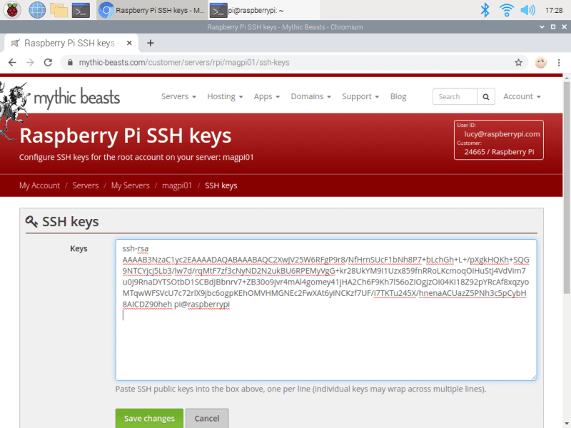
    The output will start with ‘ssh-rsa’ and end with your hostname ‘pi@raspberrypi’.
    Use your mouse to select all the output of the SSH key, then right-click and choose Copy. Now head back to the browser and click ‘configure keys’. Right-click on the large ‘Keys’ text field and choose Paste to enter the SSH key. Click ‘Save changes’.

    A secure SSH key generated on your local computer is shared with the remote computer to provide access

    SSH access

    Scroll down the server window and take a look at the details in SSH access. Here you will see your Username, Host, Port, and Authentication information. You will use this information to connect to your Raspberry Pi server. There is also a Command section, with the Terminal command used to connect directly. Ours looks like this:

    ssh -p 5274 root@ssh.magpi01.hostedpi.com

    Copy and paste the command into the Terminal and press ENTER.

    Respond ‘yes’ at the ‘continue connecting’ prompt and your SSH key will be added to your list of ‘known hosts’.

    If you created one, you’ll need to add the SSH key password when prompted. When logged in, the command prompt will change to root@raspberrypi. You are logged in as ‘root’ and in the root user’s home directory ‘/root’.

    Install a web server

    We’re going to use the Apache web server, which you can install with the following commands:

    apt update
    apt upgrade -y
    apt install apache2 -y

    Note that you don’t need to use ‘sudo’ as you are the root user.

    Open a web browser and visit the following URL (replacing ‘magpi01’ with the name of your own hosted server: magpi01.hostedpi.com.)

    This will display the Apache2 Debian Default webpage with an ‘it works!’ message.

    This page is an HTML file located on your remote Raspberry Pi, at /var/www/html/index.html.

    Navigate to this directory in the Terminal and have a look at what’s inside:

    cd /var/www/html
    ls -al cat index.html

    Install PHP

    We now have the ‘L’ and ‘A’ of our LAMP server: Linux and Apache. The M and P come next: MySQL and PHP.

    MySQL is a database system, while PHP is a programming language. You’ll need both to run most content management systems, such as WordPress.

    Now is the ideal time to add the software. You can install PHP with the following command:

    apt install php -y

    And MySQL with this command:

    apt install mariadb-server php-mysql -y

    Now restart your Apache server to ensure both services are running.

    service apache2 restart

    Upload content remotely

    You don’t need to be logged in to your Raspberry Pi server to edit content in the html directory. Close the connection with:

    exit

    You can send files directly to the html directory from your local computer using secure copy (scp).

    First, we’re going to get a photo (of our cat) and name it cat.jpg. Then create an index.html file.

    nano index.html

    And enter this basic HTML code:

    <html> <head> <title>Siouxsie</title> </head> <body> <p>Our cat, Siouxsie!</p> <img src="cat.jpg"> </body>
    </html>

    Copy the two files directly to the html directory on your remote Raspberry Pi server:

    scp -P 5274index.html cat.jpg root@ssh.magpi01.hostedpi.com:/var/www/html/

    …making sure to replace the ‘5274’ and ‘magpi01’ parts with the port and hostname of your Raspberry Pi server. Press F5 to refresh your web browser and view the new webpage design.

    Test out PHP

    Let’s test that PHP is working, and also take a look at the index page for our website. Create the file index.php:

    cd /var/www/html
    nano index.php

    Put some PHP content in it:

    <?php echo "Hello, World!"; ?>

    Save the file and close with CTRL+O and CTRL+X.

    Now get rid of the index.html file (because it takes precedence over the index.php file):

    rm index.html

    Reload your website in the web browser and you will see ‘Hello, World!’. This page isn’t dynamic, but it’s created with PHP code.

    A LAMP (Linux, Apache, MySQL, and PHP) server can be used to run a WordPress-based website

    Install WordPress

    Now we’re going to head back into our remote server and do something a little more detailed. We’re going to set up WordPress, a popular CMS (content management system). This makes use of our PHP and MySQL database and is a great option if you’re looking for a powerful website with a minimum of coding.

    Log back into your remote Raspberry Pi server.

    ssh -p 5274 root@ssh.magpi01.hostedpi.com

    Go to your html folder and get rid of all the content.

    cd /var/www/html/
    rm *

    Now download the latest version of WordPress:

    wget http://wordpress.org/latest.tar.gz

    If you need to install wget, use apt install wget.

    Next, extract the WordPress tarball to get at the WordPress files:

    tar xzf latest.tar.gz

    Move the contents of the extracted wordpress directory to the current directory.

    mv wordpress/* .

    Tidy up by removing the tarball and the now-empty wordpress directory:

    rm -rf wordpress latest.tar.gz

    Use ls to view the contents of a WordPress directory inside your html directory. It will include a new index.php file along with various HTML and PHP files.

    The WordPress login page running on a Raspberry Pi web server using PHP and HTML

    Set up your WordPress database

    Although you have the WordPress files, you can’t use your website just yet. First, you need to set up the MySQL database. Enter this command:

    mysql_secure_installation

    As this is the first time running MariaDB, there is no password, so just press ENTER.

    Type in Y and press ENTER to ‘Set root password?’. Type in a password and press ENTER. Make sure you note this root password, as you will need it shortly.

    You’ll be asked four questions. Answer ‘y’ to each one: Remove anonymous users, Disallow root login remotely, Remove test database and access to it, and Reload privilege tables now.

    When complete, you will see the message ‘All done!’ and ‘Thanks for using MariaDB!’.

    Create a database

    Now that the database is installed, you need to create a database for WordPress:

    Run mysql in the Terminal window:

    mysql -u root -p

    Enter the root password you created. You should start up the MariaDB monitor and see this command prompt:

    MariaDB [(none)]>

    Enter this command:

    create database wordpress;

    If this has been successful, you should see this:

    Query OK, 1 row affected (0.03 sec)

    Now enter these two commands:

    GRANT ALL PRIVILEGES ON wordpress.* TO 'root'@'localhost' IDENTIFIED BY 'YOURPASSWORD';
    FLUSH PRIVILEGES;

    Exit the MariaDB monitor using CTRL+D.

    Open WordPress

    Open the web browser on Raspberry Pi and head to your website: magpi01.hostedpi.com.
    You should see a WordPress setup page; click on Let’s Go.

    You will see ‘unable to write to wp-config.php file’. Select all the code inside the window and right-click to copy. Now switch to the Terminal window on your remote Raspberry Pi and enter:

    nano wp-config.php

    Paste the code into the wp-config.php file in Nano, then save and exit (CTRL+O, CTRL+X). Switch back to your web browser, and click ‘Run the installation’.

    Fill out the information fields and click the Install WordPress button, then log in using the account you just created.

  • Pioneer600 review

    Pioneer600 review

    Reading Time: 2 minutes

    First of these features we noticed was a five-way joystick and 0.96-inch OLED display. This is backed up by a dual-LED and buzzer. On closer inspection, we discovered the on-board LFN0038K to enable remote control. A DS3231 real-time clock is also included (you’ll need to supply your own battery).

    There is a built-in BMP280 for measuring air pressure and temperature, but it’s the available ports for external sensors that are the key attraction: a PCF8591, 8-bit resolution, screw terminal interface, a 1-Wire device (a DS18B20 thermometer is included), a 4×4 pin sensor interface, and GPIO expansion.

    There is also a micro USB to UART connection and cable supplied. UART is normally used to debug Raspberry Pi, but with debugging mode disabled, you can send data to and from Raspberry Pi and a connected PC.

    One for the C crowd

    The physical setup is easy enough. This isn’t an official HAT (hardware attached on top) standard board, so manual installation of the various software library components is required.

    Sample programs for bcm2835, WiringPi, and Python can be found on the Pioneer600 wiki. We had more success with the bcm2835 and WiringPi sample code (both are in C) than Python, where we encountered a few errors.

    Perhaps this is better than the other way around: Pioneer600 is a professional sensor board that will find a happy home in an industrial environment running C code to sense and report on its findings. Ultimately, we recommend it to C developers over Python coders.

    Verdict

    7/10

    Pioneer600 is packed with a lot of I/O and the OLED screen is a nice touch. We found the Python sample code cranky, but the WiringPi code runs just fine. Better for C developers.

  • 10 amazing Raspberry Pi IoT projects

    10 amazing Raspberry Pi IoT projects

    Reading Time: 3 minutes

    Smart doorbell: See who’s ringing

    Internet-connected doorbells are quite popular these days. Instead of buying an expensive system, build your own, better one.

    Rosie RiOT

    Rosie IoT Brick: Outdoor IoT

    Allow friends and family to remotely track your marathon running with Rosie IoT Brick. It can also act as a GPS for the runner if required.

    PiRoomba

    PiRoomba: Robot vacuum enhanced

    The Roomba vacuum cleaner is fantastic. Using a Raspberry Pi, though, you can supercharge it like Tim ‘The Toolman’ Taylor. See PiRoomba.

    Sleepbuddy

    Sleepbuddy: Robot babysitter

    A social robot that can help looking after a child. It’s not a full-on Jetsons maid, but Sleepbuddy will help when you’re trying to enjoy some telly.

    Furlexa

    Furlexa. Nineties throwback assistant

    However you feel about Furbies, we’re sure you’ll definitely have stronger opinions about Furlexa, a smart Furby that can answer your questions. Put down the pitchforks.

    Smart Home Bulb

    Smart home bulb: Clap on

    Controlling your lights via the internet has never been easier, thanks to loads of companies now making smart bulbs you can hack.

    MudPi

    MudPi: Automated gardening

    Automated gardening is in vogue, and what better way than growing your own delicious vegetables (climate allowing) in your own garden with help from robots? Check out MudPi.

    AI Teasmaid

    Raspberry Pi AI Teasmade: Wake up to a brew

    Looking less like a classic teasmade and more like a Rube Goldberg machine, this AI Teasmade contraption will nevertheless make you a cuppa – possibly while playing Powerhouse.

    Magic Mirror

    Magic mirror: Smart casual

    A now popular Raspberry Pi project, smart/magic mirrors are an amazing way to make sure you’re ready for the morning.

    PiClock

    PiClock
    Time and weather

    A classic use of IoT is the weather. Turn a Raspberry Pi into something that powers a lovely PiClock that also displays the weather.

  • Petoi Bittle robot dog has bite

    Petoi Bittle robot dog has bite

    Reading Time: 2 minutes

    The teachable robot pet promotes STEM learning and reached its $50K Kickstarter fundraising goal. It went on to attract nearly ten times that amount in the subsequent month-long campaign period.

    The tiny robot dog is its maker Petoi’s second such endeavour: earlier this year it started shipping the successfully crowdfunded Nybble, an open-source robot cat.

    Robot pets have been around for more than a decade, but the extensible nature of the Petoi pets makes them ideal for learning how to control robots yourself. Petoi aims to bring down the cost of consumer robots.

    At around $225 for the Bittle kit, it’s aimed at adult tech enthusiasts. Unlike robot toys marketed at children, Bittle is a quadruped with controllable legs. This makes it closer to a £1000+ Sony Aibo robot dog although the design nods to Boston Robotic’s industrial Spot robot.

    Bittle has an Arduino controller board for the legs, while Raspberry Pi adds AI elements to the build such as image recognition and tracking. Bittle backers receive components of the robot dog and can share their pet’s exploits with others on a dedicated forum.

    New dog; old tricks

    As any Lego, Meccano, or train set designer will tell you, the enjoyment is in the construction at least as much as the finished article.

    The pet robot will be modular and Petoi claims it takes around an hour to assemble. Its maker explains that the pet dog is assembled from a ‘puzzle-like frame’ with demo codes downloadable from a GitHub page. Bittle can go for a walk, avoid obstacles, and right himself if he falls down steps.

    While teaching Petoi tricks will bring its own rewards, there will also be a competitive element. Owners can entertheir robot pet into a virtual dog show and demo the skills they’ve both learned.

    Arduino and Raspberry Pi provide the robot dog’s controls and artificial intelligence

  • Air Hockey Robot

    Air Hockey Robot

    Reading Time: 2 minutes

    Out of thin air

    The pair built the whole project from scratch, taking about a year. “A lot of work had to be done before even thinking about the actual implementation of the robot controlling the other side of the table,” reveals Ondřej. “It would be hard to pick the most difficult element. We had to overcome a lot of challenges, including electrical wiring of all the chosen hardware, robot movement control algorithms, computer vision, game strategy algorithms, user interface etc.”

    After designing the table in Fusion 360, it was constructed from spruce and plywood with an Alubond playing surface. To ensure smooth gliding of the puck, a square mesh of 920 holes was drilled into the game board, enabling air to flow through from two fans located under the table.

    As for the mechanical aspect, the pair opted for an ‘H-bot’ design to move the robot’s paddle. Held in a 3D-printed housing, the paddle is moved around using a pulley and belt system, with two stepper motors controlled by an Arduino Micro. “[The H-bot design] is really the best solution for this problem as both steppers are stationary,” explains Dominik.

    Look and learn

    The inner workings of the table revealing the two fans and extensive wiring required

    The processing power for the robot’s optical puck recognition and AI strategy is provided by a Raspberry Pi 4. It is connected to a Camera Module V1 mounted in the overhead part of the frame, along with LED strips to ensure good lighting. With the camera capturing frames at around 80 fps, OpenCV is used to recognise the bright green puck so its position can be determined.

    For the robot’s strategy, Ondřej and Dominik originally planned to use machine learning. That proved a step too far, however, given all the other fine-tuning issues that they faced in making the project. “Using machine learning was the plan from the beginning,” says Ondřej. “But, trust me. We tried. We tried a lot to make it work. But it was literally impossible to implement, given how hard it is to train an agent in such a complex state space with even more complex action space.”

    Instead, they manually programmed four types of strategies with slightly different algorithms – you can find the code on GitHub.

    The project’s Raspberry Pi is also connected to a touchscreen with a GUI made using Kivy. Apart from the purposes of setting up the game and keeping score, this makes it possible to “set all kinds of parameters ranging from camera properties/calibration and motor speeds to the type of strategy,” explains Ondřej.

    The Air Hockey Robot was a very complicated and time-consuming project, but the result is indeed a brilliant piece of engineering and programming, where only the quick-witted can win. So, how often have they actually beaten the robot? “30-40% of the time. More at the beginning when things were not tuned out,” says Dominik. “But, it got harder and harder. Especially for the not so good players that we are.”