Microsoft Flight Simulator 2020 Gameplay Review + Bonus Videos
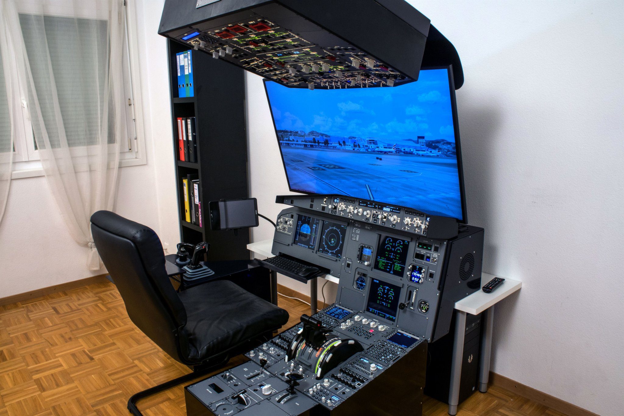
Reading Time: 2 minutes The Real Deal Simualtor: If you want to buy your own, here you can do so: https://store.ncinformatique.ch/en/product/panel-a320-desktop/ Description from the website: FO side of the Panel A320 Desktop is now available in option ! It functions with only one external computer and can be connected easily with only 4 cables ! 3 USB, […]