Kategorie: Reviews

  • ExoMy 3D Printed Mars Rover

    ExoMy 3D Printed Mars Rover

    Reading Time: 3 minutes

    The terrain on Mars is notoriously difficult, so any vehicle intent on exploring the Red
    Planet needs to be pretty hardy. Something small and agile, powered by a dependable yet
    powerful on-board computer, is likely to fare best against such unforgiving terrain.
    Something, perhaps, like a Raspberry Pi. “The rover is inspired by the ExoMars rover Rosalind Franklin and features its most
    characteristic design features (drill, solar panels, wheels),” explain ExoMy’s makers
    Maximilian Ehrhardt and Miro Voellmy from the ESA’s Planetary Robotics Laboratory. “Its
    triple bogie locomotion suspension and six steerable wheels allow for locomotion in very
    rough terrain and [also mean it’s able to traverse] obstacles larger than the size of the
    wheel.” Better yet, ExoMy can be controlled using a gamepad or a web interface where the
    video stream from its on-board Raspberry Pi camera is also displayed. Raspberry Pi 4 Model B is the ExoMy’s main board computer, receiving driving commands
    via the web interface. Raspberry Pi “converts them into motor positions and velocity, which
    are sent via I2C to the PWM motor board to make the rover move,” reveals Miro.

    Small and perfectly formed

    The rover is made from 3D-printed parts and readily available servo motors and screws, plus a Raspberry Pi 4 and Camera Module v2

    Max and Miro chose Raspberry Pi for ExoMy because it “allows the use of a full-fledged
    operating system and provides a wide variety of GPIO pins and a great camera interface.”
    They were also attracted by its low cost, worldwide availability – important given their
    ambition to make space robotics more accessible – and the large community surrounding
    it. “ROS (Robot Operating System) support meant we could use a lot of available open-
    source software and ensure that ExoMy stays very modular,” says Miro. Both engineers had used Raspberry Pi in projects before. Miro used Raspberry Pi to
    control a spherical robot at the Automation and Robotics Laboratory at ESA that floats on
    air and which simulates satellites and spacecraft control algorithms.
    Max, meanwhile, worked on a sounding rocket project at university for which he created a
    Raspberry Pi telemetry logging HAT.

    Building blocks

    Robotic engineers Maximilian Ehrhardt and Miro Voellmy

    Although other open-source rovers exist (notably Sawppy and JPL), these had customised
    metal housings and are far more expensive than the $250 to $500 required to build your
    own ExoMy. A well-received prototype had been produced by trainees in 2018, but it was
    rather costly and had reliability issues. At the start of 2020, Miro and Max set out to design
    a reliable and reproducible version that was also far more affordable. They designed all
    the mechanical parts at the Planetary Robotics Laboratory and 3D-printed them, which
    took approximately two weeks. Assembly required another two days. The electronics and
    screws all came from commercial suppliers. “The idea was that everyone interested in building ExoMy can easily order, install, and use
    it. They can even use the same software tools as in the Planetary Robotics Laboratory,”
    says Max. “We try to use as much open-source software as possible,” adds Miro. “ExoMy
    is, however, designed in SolidWorks, which is unfortunately not free.”
    Details of both the hardware and the freely available software used can be found here.

    ExoMy is intended to be replicable. This US version even impressed its notoriously inscrutable housemate, Mitchell

    Max and Miro encourage others to give it a try and advocate using Docker, since it
    reduces the need to repeat installations and “allows for a repeatable and reliable software
    environment”. Discussing your design challenges with someone, getting a second opinion,
    and inviting different views of a problem generally leads to the best solutions, they advise.
    You can find out more about ExoMy by joining on Discord.

  • The MagPi magazine issue #100 special

    The MagPi magazine issue #100 special

    Reading Time: 3 minutes

    The MagPi magazine issue 100 cover

    The special red-foil cover is in Raspberry Pi colours (red and white) and unfolds to reveal all 100 covers of The MagPi magazine. Inside the special edition is a 20-page feature celebrating 100 moments from Raspberry Pi history.

    100 moments: The MagPi's amazing achievements

    Discover 100 Raspberry Pi moments

    We’ve scoured the previous editions, talked to all the community, and all reminisced over eight years of Raspberry Pi. The results is 100 greatest Raspberry Pi moments, achievements, and events from 100 editions of The MagPi magazine.

    Santa's Run

    Make Santa’s Run with recycled bottles

    Mike Cook serves up a double-whammy for Christmas with a game that has you delivering all 100 editions of The MagPi. Santa’s Run uses recycled plastic bottles as controllers. 

    The ExoMy Mars Rover is just one of many amazing projects in The MagPi #100

    ExoMy Mars Rover and other amazing projects

    We’ve gone all out this month with some of the best community projects ever to feature in The MagPi magazine. Like ExoMy, the low-cost Mars Rover designed to be 3D printed at home. 

    Build your own Handheld Console with Raspberry Pi

    Build a handheld console

    KG uses two of the latest handheld gaming kits to explore portable console gaming with Raspberry Pi. Combine the small size of Raspberry Pi Zero with battery power and a small screen to game-on-the-go.

    The MagPi magazine #100 is packed with information on Raspberry Pi 400

    Say hello to Raspberry Pi 400

    Raspberry Pi’s all-in-one desktop computer combines the power of Raspberry Pi 4 with the official keyboard. Repositioning all the ports to the back, we feel it’s Raspberry Pi perfection. Our feature benchmarks, tests, and gets inside the latest Raspberry Pi.

    We review Argon ONE M.2

    Argon One M.2 review

    Super-charge Raspberry Pi with a super-fast M.2 SATA SSD drive for vastly improved storage performance. We are impressed with the latest Argon ONE M.2 case, which delivers on multiple fronts.

    The Top 10 Festival Projects in The MagPi #100

    10 amazing festive projects

    Light up the holiday period with our guide to festive illuminations, decorations, and ornamentations. It’s the perfect way to weave digital making into your festive break.

    Learn Raspberry Pi OS with these amazing resources

    Learn Raspberry Pi OS

    Newcomers will find our guide to Raspberry Pi OS (the operating system at the heart of Raspberry Pi) invaluable. But even experienced makers will find something to learn from this collection of incredible Debian and Raspberry Pi OS guides.

    Pick up your copy of The MagPi magazine#100

    The MagPi magazine is available as a free digital download, or you can purchase a print edition from our Raspberry Pi Press store.

  • The MagPi 100 mega competition!

    The MagPi 100 mega competition!

    Reading Time: < 1 minute

    Subscribe

  • Holiday Projects for a Festive Home

    Holiday Projects for a Festive Home

    Reading Time: 5 minutes

    We’ve put together a selection of fantastic community projects to give you some inspiration
    for decorating your house inside and out. Let’s get festive.

    Outdoor decorations

    Light up your street with pure seasonal cheer (and some LEDs)

    Xmas lights for beginners

     Your house could look like this, with careful use of a ladder

    Sometimes you need to do something a little grand, especially for the holidays,
    and lighting up the outside of your house is certainly one excellent way to do it. If you’re
    not sure where to begin with this, then this guide by Makin’Things will not only get you set
    up with lights, but also how to get them to sync up with music. It uses the excellent lightshowpi Python library (lightshowpi.org) to make the music
    syncing fairly easy. It also uses relays and a lot of power, so be extra careful if you plan to
    follow it! magpi.cc/xmaslightsbeginners

    2018 Christmas Light Show

    You might want to warn your power provider before switching these on

    Are you really doing your outside lights correctly if you’re not worrying your
    neighbours? If you really want to see how much you can do with lightshowpi and the kind
    of setup Makin’Things does, this light show which includes lawn ornaments, a tree, and
    4000 lights should give you some inspiration. It’s all still controlled by music as well. Once again, you’ll need to be extremely careful with
    heights and electricity use if you plan to recreate this. magpi.cc/2018lightshow

    LED display matrix

    The matrix is fully programmable to show images and scrolling text

    If you don’t fancy doing the whole house, then maybe a window will do! Andrew
    Oakley shows you through how to create a set of animated LEDs for not too much money.
    It also takes PNG images, so you don’t need to program each individual LED and it can
    even scroll text as well! While relatively simple and cheap, you may have to do some woodwork, so get it started
    ahead of time and make sure to be careful when using any carpentry tools. magpi.cc/ledmatrix

    Power up your tree

    Even with just a fake Christmas tree, you can really bring it to life with a
    Raspberry Pi

    Smart Christmas tree lights

    You can use a bigger tree if you have enough NeoPixels

    Not only are these Christmas lights made with fully programmable NeoPixels,
    giving you unlimited flexibility in colours and patterns, but they also add voice control so
    you don’t even need to touch them! Sure, you could implement some remote SSH system,
    but this way is a bit more fun. We made this in The MagPi last year and we think it still holds up! You may want to invest
    in a little 5V power supply adapter as changing out batteries all the time does get a little
    boring. magpi.cc/smartxmaslights

    Tree Star

     If you can find a translucent printing material, that will work best

    Another The MagPi original, this one uses a 3D-printed star to act as a tree
    topper, with some LEDs installed inside to light it up! It’s been a few years since we
    selected this specific 3D star file from Thingiverse, so you might be able to find something
    better or whip one up yourself.

    Make sure to scale the star for your tree, though – behind the scenes, this star wouldn’t
    stay on the original tree we had and we needed a bigger one! If you’re doing the smart tree
    lights as well, you can easily combine the two. magpi.cc/64

    YouTube Christmas Ornament

    With the right 3D-printed parts, this can look very natural

    We all know someone who needs to see the Coca-Cola Christmas advert
    before Christmas starts for them. You may even be that person! Relive all your favourite
    Christmas adverts through this ingenious build that puts a tiny display on your tree to play
    them all. You have to supply the videos yourself, though, so if you really want to embarrass
    someone, you’ll need to digitise some old VHS tapes of Christmas past and upload them.
    Or just put your favourite Christmas films on there. magpi.cc/xmasornament

    Deck the halls

    Give the rest of your home a bit of seasonal magic

    Christmas house and snowman

    The light display is really very nice, with alternating colours on a slow cycle

    This little diorama was created by Stewart Watkiss (aka PenguinTutor) to be
    part of an outdoor railway. However, it also functions as an indoor decoration. A string of
    LEDs on the front of the building act as some nice Christmas lights, and a snowman has
    NeoPixels inside so it can glow with awesome Christmas power. The house and snowman were 3D-printed, although you could probably find some model
    kits that will allow you to do similar. We like the snow effect on the tray, and the little tree
    and people to give it the correct sense of scale. magpi.cc/xmashouse

    pireplace

    The façade is pretty fun, although you could probably add fake logs if you really wanted

    We must admit, we don’t /quite/ get the appeal of the fake fire on the TV during
    Christmas. This we can get behind, though – creating a fake fireplace and adding
    NeoPixels to create a warming fire effect that is sure to cozy up any room. It’s even got a web interface you can control from your phone, allowing you to change the
    colours and turn it on and off. Very handy, and maybe a little spooky if you time it right to
    catch folks in the act of present-feeling. magpi.cc/pireplace

    Smart gingerbread house

    The door opens and closes, which is pretty excellent

    Gingerbread houses are a classic Christmas ornament for some families – one
    that probably wouldn’t last to Christmas Day intact in our house. Estefannie decided to
    take it about two steps further, as she’s wont to do, and fully automated a smart
    gingerbread house. It’s also covered in enough sweets to attract Hansel and Gretel.
    The whole thing also has a remote control function so you can switch the lights on and off,
    open and close the door, and a lot, lot more. magpi.cc/gingerbread

    Sense HAT advent calendar

    The version you’ll make will let you know what day it is when you ‘open’ the door

    Too impatient to wait until Christmas Day for your presents? Then how about a
    slow drip-feed of daily gifts like you’d get in an advent calendar? This digital version
    doesn’t give you chocolates, unfortunately, but it is a neat and simple little project to help
    you get into the festive mood. It’s from the Raspberry Pi Projects website, so it’s nice and easy to set up and requires
    very few components as well, relying more on code than anything else. magpi.cc/senseadvent

  • Build a Home Assistant with Raspberry Pi

    Build a Home Assistant with Raspberry Pi

    Reading Time: 6 minutes

    Nevertheless, many have concerns about subscription costs and privacy of the data
    collected. The good news is that many open-source Raspberry Pi automation systems
    have matured significantly over the past few years. They now challenge the big players,
    are free of charge, and put your privacy first. Over the next three issues we’re going to set
    up a smart home from scratch.

    Step 01: Your new Home Assistant

    To make our home a more fun place to be, we’re going to set up a home automation
    system. This is software that can communicate with multiple devices and make changes to
    your environment based on a rule set. Sounds a bit complicated, but the ‘HA’ scene has
    got a lot friendly over the past few years. We’ve chosen the appropriately named ‘Home
    Assistant’ (home-assistant.io) because it is a complete operating system package and
    runs well on Raspberry Pi 3 or above. Best of all, it has incredible support for hundreds of
    smart devices.

    Step 02: Installation and first boot

    Home Assistant is available as a full microSD card image – no operating system installation is required in advance. To get the image, go to magpi.cc/homeassistantio. Make sure you pick the right one because different images are available for Raspberry Pi
    3 and 4. Once downloaded, burn the images to a microSD card using Raspberry Pi Imager
    (magpi.cc/imager). We strongly recommend using a wired Ethernet connection for
    reliability. Whichever you choose, use a wired connection when booting up for the first
    time. Be patient, Home Assistant will take up to 20 minutes to start up on first boot.

    Home Assistant runs in your browser or as a smartphone app

    Step 03: Terminology

    Before going any further, it’s useful to understand the terms used in Home Assistant.
    Take a look at the ‘Home Assistant terms’ box and understand Integrations, Devices,
    Entities, and Areas. Take some time to become familiar with the terms while Home Assistant is setting up.

    Step 04: First connection

    After 20 minutes (don’t worry, it’s a one-time thing), you should be able to see a welcome
    screen. Open a web browser and visit: http://homeassistant.local:8123/. If not, try using a network utility like Fing for iOS or Android to locate the IP address of the
    server and try that instead. If you still can’t get a connection, try waiting a little longer.
    Eventually, you should see a ‘Preparing Home Assistant’ screen. This will shortly change
    to an account creation screen. Home Assistant has full support for multiple accounts with different permission levels. The
    account you create here will have full control over the system.

    The default overview shows you weather and sunrise times. These can be used to trigger events

    Step 05: Initial settings

    Once you’ve completed the form and created your first account, you will be asked to select
    your location and give it a name. This information never leaves your network and is used
    to get information on sunrise and sunset times for where you are. You can also choose
    your preferred unit of measurement. These details can be changed at any time. You’ll now be taken to the Overview dashboard, the heart of the system. A dashboard is a collection of panels that display various bits of information and allow you to control your environment. Your system is already up and running.

    On installation, Home Assistant will attempt to discover smart devices on your network. You may be surprised how many devices are available

    Step 06: Your first dashboard

    The Overview dashboard has been populated with some initial panels. Largest is the
    weather panel, based on your location. You will also see ‘badges’ at the top. Try clicking

    on the Sun badge for data about today’s sunrise and sunset. There will also be a person
    badge which will probably say UNK for ‘unknown’. We’ll come to that later. For now,
    explore the left-hand menu. You can see a map (this will get more useful), a log of all
    events, and several configuration options. You’ll also see Notifications – the chances are,
    you’ll have one waiting. If you do, Home Assistant has discovered things on your network
    that it can talk to.

    Using custom panels, we can provide a clear view of our printer’s ink supply

    Step 07: Your first integration

    Did you click that notification in Step 5? If so, you’ve probably been informed that Home
    Assistant has already found some devices on your network. It can be surprising how chatty
    some things can be. Printers, routers, and media systems such as Sonos will all happily
    introduce themselves to Home Assistant. To actually start using the integrations, click on Configuration then Integrations. Now click Configure on your choice of integration. Some additional information may be required, but often auto-discovered integrations work out-of-the-box. If a particular integration is not of interest to you, click Ignore to hide it.

    Step 08: Automatic dashboards

    Once you’ve enabled and configured some integrations, go back and have a look at the
    Overview dashboard. Home Assistant will have automatically added an appropriate panel
    to show data or add controls. If you have a Philips Hue or Ikea Trådfri gateway, your lights
    will have been discovered and added to the panel. This feature makes getting started with Home Assistant a breeze. If you’re happy with this, you can let Home Assistant update and configure your panel as you add new integrations and devices. However, if you want full control, you can disable this feature and create your own panels.

    The Overview dashboard includes a weather forecast for your location, along with ‘badges’ at the top

    Step 09: Your own dashboard

    When we installed our Home Assistant, it found our networked printer and created a panel
    that showed the ink levels for each cartridge. It’s a bit dull, so let’s make a better one. By
    clicking on the three dots at the top-right of the screen, we can Configure the UI. You’ll see
    a warning that automatic configuration will be disabled. You can now edit, move, delete,
    and add new panels. You can also add tabs across the top and you can have as many
    dashboards as you like. We created a new tab for our printer.

    Step 10: Adding panels

    We now have a nice, clean area to work with. Click the + icon at the bottom-right to add new panels. You will see all the default panels available, covering many different use
    cases. These include switches, gauges, playback control for media centres, and many
    more. You can even design your own. We clicked the ‘gauge’ panel as that seemed best
    for printer ink. Home Assistant is helpful enough to work out what entities are best for the
    type of panel and you can control certain aspects such as warning thresholds. We added a
    gauge for each of our printer ink cartridges.

    Step 11: Adding new integration

    We strongly recommend spending some time looking at the available integrations. Click on
    Configuration, Integrations, then click the + icon. You will be presented with a bewildering
    list of possibilities. We found an integration for pi-hole, the ad-blocking service. After
    entering the address of our Raspberry Pi 4 running the service, we had a panel full of stats
    to look at. Some integrations increase the capability of Home Assistant to talk to other
    devices. For example, the MQTT (Message Queuing Telemetry Transport) integration
    allows Home Assistant to subscribe to MQTT topics and trigger events. If you’re handy
    with Python, you can create your own custom integrations too.

    Step 12: Going mobile

    If you’ve set up all your lights to work with Home Assistant, it’s going to be a bit pointless if
    you have to run to a computer every time to need to flick a virtual switch. An essential part
    of any Home Assistant setup is the smartphone app (iOS or Android). This not only allows
    you quick access to your dashboards, but also adds you as an entity.

    The app communicates with Home Assistant and provides location and activity information. All your health stats tracked by your phone can be added and your location reported. All this data stays in your network and you can switch it off any time, but there are great possibilities that we’ll look at next month.

  • Learn Sense HAT with Raspberry Pi

    Learn Sense HAT with Raspberry Pi

    Reading Time: 2 minutes

    Astro Pi resources

    This versatile board was designed especially for a space mission. Two Astro Pi units
    – comprising a Raspberry Pi with Sense HAT in a special case – are currently
    aboard the International Space Station (ISS), orbiting 408km above the Earth. Astro Pi is an ESA (European Space Agency) project run with the Raspberry Pi
    Foundation. It enables young people to conduct scientific investigations in space by
    writing computer programs that run on the Astro Pi devices aboard the ISS. Students
    up to 19 years old can take part in the Mission Space Lab, while those 14 and under
    can get involved in the simpler Mission Zero. Even if you don’t want to take part, Astro Pi has a solid set of resources designed to
    help students set up the Sense HAT and collect data from it.

    Experiment with the Sense HAT

    While no longer available in print form, this compact book from The MagPi Essentials
    range can still be downloaded as a free PDF. An extensive feature on the Astro Pi
    mission details how the units were designed and then launched into space to reach
    their new home on the International Space Station – to be joined by British ESA
    astronaut Tim Peake soon after.

    Sense HAT book

    The book then launches into some step-by-step tutorials to help you get started with
    your Sense HAT, demonstrating how to display images on the LED matrix and how
    to read the various sensors on board, including the gyroscope, accelerometer, and
    magnetometer. Fun projects to code include a Gravity Simulator, Digital Magic 8 Ball,
    Interactive Pixel Pet, Astronaut Reaction Times Game, and Data Logger.

    Raspberry Pi Projects

    Raspberry Pi projects

    The Raspberry Pi Foundation’s learning resources website features several tutorials
    to help you get started with your Sense HAT and make some fun projects with it
    using Scratch or Python. Even if you don’t own a Sense HAT yet, you can
    experiment with writing Python programs in an online emulator to see the effects.
    Start with a simple Countdown Timer on the board’s LED matrix, before moving on to
    games such as Flappy Astronaut, Marble Maze, Tightrope, and Pong. More complex projects include an MP3 Music Player and Weather Logger. There's
    even a tutorial to explore SpaceCRAFT – a winning Astro Pi competition project – in which you can visualise data from the Sense HAT’s sensors in the Minecraft world.

  • Tap-an-LED: client add-on board

    Tap-an-LED: client add-on board

    Reading Time: 7 minutes

    Step 1: All USB devices are not the same

    Many people tend to think you can plug any USB device into any other, but this is not strictly true. The sort of USB connector on a Raspberry Pi computer is USB-A. This connector is always used by a USB host device, like a computer. A host device supplies power and is in control of the process of communicating with the other sort of device, a USB client device. If a client wants to pass information to a host, it has to wait until it is asked by the host if it has anything to say.

    Step 2
    : Interconnectivity

    You can’t plug a host into a host, nor can you plug a client into a client. Quite simply, the connectors on the USB cable will stop you doing this – even if you make up a special cable. it simply would not work. So while it is fine for a Raspberry Pi computer to connect with a MIDI sound module, you can’t connect it to a DAW (digital audio workstation) like Reaper or Ableton running on an other Raspberry Pi computer or other laptop. This limits the role your Raspberry Pi computer can play in a MIDI system.

    Block diagram of complete system

    Step 3
    : Solving the problem

    You could use a MIDI interface cable on both computers and connect the MIDI sockets up with a couple of MIDI leads, but we have found this seldom works because of the accuracy of the baud rate produced by these interface leads. So, we have come up with a solution to get round this by enlisting the help of an Arduino, like we have done in the past. But this time we will be using a different sort of Arduino, the Pro Micro, based on the ATmega32U4 chip. We get the bonus of using the Arduino’s peripherals as well.

    Copper side of GPIO extender

    Step 4
    : How does this work?

    The idea is that the Arduino presents a USB MIDI client interface to a host and the we can communicate with it from the Raspberry Pi computer using its serial port. This can be at a fast rate, and we are not faced with the problem of trying to get the serial port to use MIDI speeds, which are not directly supported. The block diagram of this project is shown in Figure 1. While we could wire the Arduino to the same cable as our Tap-An-LED box, we did not want two boxes permanently joined together with a common flying lead.

    Step 5
    : Making the GPIO connector extension board

    To get round this, we made a little 12-pin GPIO extender board so that we could use the two boxes together. This is simply a piece of stripboard 16 hole by 6 strips – Figure 2 shows the track cuts on the underside. To the copper side, solder a 12-pin 2-row surface-mount socket; to the front, solder two 12-pin 2-row header pins. Figure 3 shows this, along with the way in which it is wired up. To save it looking too messy, the two stages of the wiring are shown separately, and a photograph of the finished item is shown in Figure 4.

    Wiring of GPIO extender shown in two stages

    Step 6
    : The Arduino board

    There are two types of Pro Micro Arduino: one with a mini USB connector, and one with a micro USB connector. We prefer the mini connector, as it tends to be more solidly attached to the board. It is slightly wider than the one with the micro connector, but either would fit on the stripboard shown in Figure 5. On the reverse, each strip row is broken in the middle to prevent the board from shorting out. The board has straight header pins soldered to it and there is a matching socket soldered to the stripboard.

    Photograph of GPIO extender

    Step 7
    : Powering the Arduino

    The link on the top corner of the Pro Micro is left open. This means the board runs at 3V3 (3.3V) and is only powered when it is plugged into a USB host. To stop the Raspberry Pi damaging the board with a serial signal when the Arduino is unpowered, a 3K3 (3.3kΩ) series resistor is inserted in Raspberry Pi’s TX signal line. On the front panel is a 20-pin 2-row socket to access the peripherals of the Arduino. For clarity, the diagram shows this connector as being split into top and bottom halves, but it is just one socket.

    Wiring of the Arduino board

    Step 8
    : The box

    We made the box using our normal method of 30mm pillars holding the top and bottom apart, with the sides glued together as a ring. The TX and RX LEDs on the Arduino are useful in seeing if MIDI messages being sent, and received. So that we could see the LEDs blink, we used two 13mm long, 6mm diameter, clear acrylic rods glued in the top to act as light pipes,. A message is being passed when the LEDs are off. Figure 6 shows the assembled box. The layout drawing for this box, and more construction photographs, can be found on our GitHub site (magpi.cc/pibakery).

    Step 9
    : Bonus I/O

    As we had an Arduino, with all its peripheral goodies doing nothing, we brought them out to a 20-way socket on the box lid. The pinout of this is shown in Figure 7. We have access to 16 different pins and over half of them are dual function. For example, we can use pin 13 of this connector as a PWM-capable digital pin 6, or as analogue input A7. You can only choose one of these two functions to use at any one time. The API for communicating with these peripherals is shown in Figure 8.

    Photograph of the Arduino board and box

    Step 10
    : The Arduino software

    The Arduino software uses the MIDIUSB library, to present itself as a MIDI HID (human interface device) client device when plugged into a host. This communicates with the host by using four numbers to define a MIDI message; we call this a ‘frame’. These frames can be transferred to and from the host by the Arduino and also passed to and from Raspberry Pi. The Python software then uses these frames to deal with messages sent to it, or generate messages to send to the host or communicate with the Arduino peripherals.

    Arduino peripheral connector pinout

    Step 11: Applications

    We have written several applications to demonstrate the capability, and workings, of our client interface, both with and without using the Tap-An-LED interface. Many of these look a lot better as a movie, rather than a still. For example, we have four midi_note_display programs. These take a stream of MIDI note messages, sent by the host, while playing a MIDI file – and LEDs or Raspberry Pi’s screen change accordingly. The colours used are changed according to the velocity of the note. LEDs and the screen can display keyboards, or a unique LED for each note – see Figure 9 for one example.

    How the software accesses the Arduino peripherals

    Step 12
    : More applications

    There is xy_pad.py, an example of using the raw data from the touch sensor screen to control two parameters as an X-Y pad in Ableton. In addition, midi_duet.py fires random notes, in the key of C, into Ableton for you to play along and improvise against. Then there is peripheral_request.py for getting and setting data from the Arduino’s peripheral pins. To go along with all this, we have all the Ableton Live sets you need to work along with these examples. Many musical interfaces you can buy come with a licence for a cut-down version of Ableton Live.

    Five keyboards showing MIDI note messages being sent on different channels

    Step 13
    : Other DAWs

    There are many more DAWs (digital audio workstations) other than Ableton. There are top-end applications like Apple’s Logic Pro X or FL studio, as well as free ones like the Windows-only Cakewalk, or the Apple-only Garage Band. Also, there are budget DAWs; perhaps one of the best of these is Reaper. Garage Band has very good-quality sounds, but the big problem we see with it is that the MIDI works for only one instrument and the implementation of MIDI controls is limited. There are many more DAWs if you search for ‘Free DAW’.

    Make sure you catch up with Part 1 of this Tap-an-LED series in issue #97 of The MagPi Magazine, and Part 2 in issue #98.

  • Lyra Handheld Game Console review

    Lyra Handheld Game Console review

    Reading Time: 3 minutes

    The Lyra Handheld Game Console (£229 / $300) is attempting to change that. After a successful launch in July 2019, Kickstarter veteran Creoqode set out to make a handheld
    gaming system that looked the part, was easy to assemble, and was more powerful
    than any other Raspberry Pi-powered handheld game console on the market at the
    time. The result is Lyra, a handheld game console that is available in kit form (or fully
    assembled if you fear nuts and bolts) and utilises the power of Raspberry Pi
    Computer Module 3 Lite. Unlike many other Raspberry Pi-based handheld game consoles available today, the
    Lyra resembles the form factor of a Sony PSP and Nintendo’s Game Boy Advance,
    which makes a nice change to the tried-and-tested Game Boy-style systems, along
    with the bonus of a larger, widescreen display.

    Easy assembly

    When the Lyra arrived, we were impressed with the packaging, which can double up
    as a protective case when your Lyra is not in use, and the quality of the parts in the
    kit – we loved having the option of clear or black buttons to choose from.

    Small yet powerful. The supplied Raspberry Pi Compute Module 3 Lite provides plenty of processing power

    As we are partial to a bit of tinkering, we opted for the kit version, so we had to assemble our Lyra ourselves. Whilst there were no physical instructions provided, the online
    tutorial is packed with detailed photos and step-by-step instructions and we had our
    Lyra assembled in under 15 minutes. The fiddliest part was attaching the screen when closing the case! For convenience, Creoqode has created a custom-built image that utilises RetroPie, so once this was downloaded and flashed to our microSD card, we were up and running in no time. It’s a shame that a manual install guide was not available for those who prefer setting up RetroPie to work on the Lyra themselves, especially as pre-build SD card images can quickly become outdated.

    Small but mighty

    One thing we liked about the Lyra was the inclusion of the Raspberry Pi Compute
    Module 3 Lite (CM3L). Whilst pricier than a Raspberry Pi Zero, the CM3L brings the
    power and small footprint that is perfect for a handheld game console.

    The packaging is well-designed and sturdy, and it makes a great storage case when your Lyra is not in use

    The CM3L clips into Creoqode’s custom-made circuit board and whilst the lack of WiFi is a
    shame, the micro-USB port allows you to connect your own USB devices (with the
    help of an adapter) for Internet connectivity. The addition of an HDMI port allows you
    to connect your Lyra directly to a large display / TV, which is great for gaming at
    home too. We did notice that the case didn’t quite close perfectly, so small gaps were visible by
    the micro-USB charging and headphone ports, and the lack of a screen protector
    was a shame, but the performance of the Lyra is second to none in a competitive
    market for handheld gaming.

    Verdict

    8/10 The Lyra is a great product in a competitive market. Assembly was straight forward
    and the power the CM3L brings is fab. The case could be better, but for gaming on
    the go, it is ideal.

  • Christina Foust Interview

    Christina Foust Interview

    Reading Time: 3 minutes

    While she’s always been a part of the streams, more recent ones have been taking place much later in the day UK time so that they’re more accessible to American students. “We’re having a lot of fun!” Christina tells us. “It’s honestly the highlight of my week, and
    we’re getting a positive response from the community. It’s really been nice to connect with
    professionals and youth creators and share their experiences with the community. I’m
    excited to see where the live stream adventure takes us!”

    How did you first learn about Raspberry Pi and related programmes?

    Honestly, I learned about Raspberry Pi when I found the job listing in November 2017. I
    was in a temporary admin role supporting school while the principal was on parental leave,
    and I needed a job! I knew about Arduino because my dad made projects, and I knew
    about coding and Scratch because I was a teacher, but I had never heard of Raspberry Pi
    before. Even during the interview process, the focus was on our clubs’ programmes in the
    USA. Then when I got the job (YAY!) and was meeting all the teams, I truly started to grasp
    the global reach of both the hardware and our education programs.

    The weekly streams have been running for months now, and you can catch them every Wednesday!

    To be honest, I had friends who were familiar with Raspberry Pi and were confused by
    why/how Raspberry Pi had hired me, a former teacher and not an experienced hardware
    or software engineer. I also had friends who thought I made a career change and was
    working at a bakery. I share the above because I want folks who are reading this to know
    that they can and should apply to jobs that interest them. I got this job because I am an educator, I love kids, and I’m good at community engagement. If I had listened to one group of friends, I might have felt I wasn’t qualified to work at RPF or if I listened to another group, I might have thought that working at a place named after a fruit would be a poor career decision. Applying to this job was one of the best decisions I ever made.

    How did the current Digital Making at Home streams come about?

    Christina and Kevin Johnson help oversee the big USA version of Coolest Projects!

    Digital Making at Home was (and still is!) our response to supporting young people and
    families staying at home this year. In March, we put together a small (virtual) team to think
    creatively about what we could do to support the community at this time while we are also
    staying home. We started with recorded code along videos and got feedback that folks
    wanted to interact with us live, so we created the live stream, and I absolutely love how it’s
    evolved to include conversations and coding with people from all over the world!

    What other stuff have you done with the Foundation?

    Being on the North America team, we’re such a small team that we all do a lot to realise
    the Foundation’s mission. So I’ve done a lot: events, clubs, Picademy, online courses! It’s
    amazing!

    Any upcoming plans you can share?

    I’m really excited about the work we are doing to prepare for Coolest Projects 2021! Stay tuned for how you can get involved!

  • Stellina review

    Stellina review

    Reading Time: 3 minutes

    This is the first time we’ve seen a product that uses a Raspberry Pi for a tracking telescope before – or more accurately, an observation station. See, Stellina (£3,643 / $4,700) isn’t just for getting a better look at the moon or maybe seeing a planet, it’s designed to look into the deep reaches of space and bring you images of nebula and galaxies that you could never see with the naked eye. And it’s all controlled from a smartphone or tablet, which is pretty clever.

    Space in your hands

    Probably the most unique feature of Stellina is how it’s not only fully controlled from
    your phone or tablet, but also you get to see what it’s pointing at from your device.
    No need to peer through a viewfinder if that isn’t your thing, although if it is your thing
    you may want to look somewhere else.

    Its modern chic look hides its function. The plastic casing isn’t quite as premium as we’d expected, though

    A Raspberry Pi 3 inside creates a local wireless network that works with a Stellina app for remote viewing and controlling. Because of this control, pointing at an object is incredibly simple: there’s a predetermined list of cosmic destinations you can select from in the app, and Stellina automatically swivels and raises its lens towards it before continuing to track it throughout the night if you so wish. The longer you look at these objects, the better picture you’ll get as the software ‘stacks’ the photos on top of each other to get a
    clearer image. You can then do some colour correcting of the image when saving it,
    or even just invert the colours for that very scientific black-on-white look.

    Chasing Saturn

    We took a Stellina out to a field in the middle of nowhere one evening to give it a proper test and we were pleasantly surprised by the results. Despite having the various planets in our solar system selectable to observe, the real magic occurs when you get it to look at nebula and galaxies. As you might expect, the darker it is the better, and some patience is required if you want to get some truly astonishing sights. Saturn was the first and last target of the evening, with barely a blurry smudge visible just after dusk, and the rings clearly circling it several hours later. Which was quite breathtaking, even if the whirring of the motors as it tracked the
    planet across the sky was a touch distracting. We feel like that this device is more aimed at folks with a balcony who’d rather be sitting inside while looking at Jupiter or Andromeda – it does claim to filter out light pollution after all. The kind of people who might have a nice balcony to put it on may also be a bit more comfortable with the hefty price tag, which runs quite a lot higher than more traditional telescope/automated tripod systems. The magic here is in the software and ease of use then, although you will be paying a premium for it – however, a much cheaper version is in the works and we’re interested to see how it compares.

    Verdict

    9/10 While the price is eye-watering, if you really like looking at stuff in space and don’t
    get out of the city much, you could have a magical time with it.

  • Smart Garden

    Smart Garden

    Reading Time: 3 minutes

    “The convergence of the two ideas was what motivated me to build it,”
    he explains. “I also liked the ‘Americana’ influence captured by the use of the Weber grill.
    Weber is an icon of the American backyard BBQ culture; I like that it can continue to serve
    up food for us humans to enjoy.“

    Horticultural haven

    Armed with his elderly BBQ and a Raspberry Pi-based Smart Garden System Kit (SGS v1)
    from SwitchDoc Labs, Etienne set to work to inject new life into the old grill. He needed to
    make modifications to both the Smart Garden System Kit and the BBQ – for example, the
    Smart Garden Kit was designed for indoor use, so Etienne needed to ‘weatherise’ it, and
    the BBQ had to be transformed into a planter box with an adequate drainage system,
    which required some carpentry and plumbing skills to be called into action. This didn’t hold
    Etienne back, however: “I found a tutorial video on building planter boxes and applied
    some of the knowledge that I learned watching it. I have built significantly more complex
    carpentry projects than this one in the past.”

    Testing the watering system before the final build

    Once his planter was ready to propagate, the technical side came into play. “The Smart
    Garden works essentially in an ‘event-based’ model,” he says. “It uses a module in Python
    called APScheduler to create recurring events. For example, it will ‘check’ the soil moisture
    sensor level every 15 minutes. If the return of this ‘check’ is below a predetermined
    moisture threshold, then an ‘alarm’ is created to water the plant.” The tank capacity is also
    monitored by an ultrasonic sensor which again triggers an alarm when the water level gets
    too low. However, the other sensors – including air quality, sunlight, and temperature – are
    for information purposes only, so no alarms are required.

    The project required a lot of soil moisture sensors

    Etienne did some tweaking to the Python code to fit his specific needs in the extreme Las
    Vegas environment – for example, he changed the soil moisture check to every five
    minutes instead of 15, so that plants wouldn’t have to wait too long to be watered, and he
    changed the length of watering time so that they got enough water. He also tells us that he
    “used a longer ‘dumb’ moisture sensor to measure deeper into the soil than the moisture
    sensors of the Smart Garden can reach. The soil moisture at seven inches deep was not
    high enough.”

    Feeling hot, hot, hot…

    So, what’s Etienne growing and how are the plants faring? Having originally planted
    tomatoes and peppers a little too late, he soon found that the Las Vegas summer desert
    temperatures proved too much for his young vegetables and they succumbed to the
    extreme heat (up to 46°C!)

     Etienne surrounded the metal frame of the BBQ with wooden panels

    That said, he’s now feeling more confident: “Now that the heat
    of the summer is passed, I have planted again for the fall season. I am growing mini yellow
    squash, mini cucumbers, and a poblano pepper plant. I am not late planting this time
    around so I am optimistic that the result will be good.”

     An ultrasonic sensor measures the tank’s water level

    Feedback from family and friends has been very positive, and it has educational benefits
    too. “They also appreciate that I do these projects, not only because I enjoy them, but to
    expose my son to STEAM educational opportunities,” explains Etienne. “I can clearly see
    the evolution of his questions over time, reflecting his increasing understanding.” He adds,
    “A mixed vegetable grilled antipasto is delicious eating for a BBQ; this Weber won’t be
    cooking it, but it might provide some of the ingredients!” It’s an excellent and pleasurable project where you should (extreme temperatures
    permitting!) have something to show for your labours at the end – why not try it
    yourselves?

  • Lunchbox Arcade Game

    Lunchbox Arcade Game

    Reading Time: 3 minutes

    He eventually chose one celebrating a different game, kicking off his Raspberry Pi-based Lunchbox Arcade Game project.

    “I used to have a cool metal Pac-Man lunch box for school but trying to get a Pac-Man one is nearly impossible, and ones that do come up go for silly money on eBay,” he explains. At more than £60 a tin, he couldn’t bring himself to drill holes in an original 1980s version. Instead, Rich decided to modify a Gauntlet one.

    Most of the parts for what became a roughly £250 build came from Arcade World.

    01 Connect Raspberry Pi to the LCD screen using an HDMI cable, then plug in an amp to the 3.5 mm audio jack.

    Lunch bunch

    Rich had already built three Windows-based arcade machines having moved on from assembling his own PCs, plus one using Raspberry Pi. For his Lunchbox Arcades, Raspberry Pi was a shoo-in. 

    “So much power in such a small form factor makes Raspberry Pi a great choice for mini arcade machines,” says Rich. “With all my machines the sound quality is important, so I’ve fitted the largest speakers the lunchbox could realistically support.” He strengthened the tin all round using plywood in the base and fitted new rivets into the metal sides. 

    02 Use a USB keyboard converter as a control block to convert arcade buttons to keystrokes. Rich suggests sourcing these from petrockblock.com

    Next came the lid. He removed the original hinge, realising it wasn’t strong enough to support the LCD screen. “I was able to gain some height with new hinges. This allows the screen to fold inside the casing, giving a seamless look when shut,” Rich says. “The joystick is removable to allow the lid to close. It’s a modified Sanwa joystick shaft with a quick release system. The sprung release shaft comes off easily and can be stored in the back of the machine. The original latch holds the lid shut.”

    It wasn’t all straightforward, though. “Airflow was also important, so a 60mm fan forces air inside over Raspberry Pi and out of two slots cut in the control panel.” With hindsight, says Rich, this could have gone on the rear rather than where the handle is. A Gauntlet fan grille he created on a 3D printer now covers it up a bit.

    Power play 

    03 The control block enables the arcade to safely shut down via the power button on the front. Attach it to Raspberry Pi using the GPIO pins.

    The Lunchbox Arcade runs off a 12V, 6A power supply. A buck voltage reducer takes this down to 5V for Raspberry Pi and the screen. “The buck voltage PCB will also look after a rechargeable battery, so I’m trying to source a 12V battery that will fit in the case and also provide a good few hours playtime,” says Rich.

    Although the project has the potential to be self-powered, he didn’t want to compromise on the speakers. “The speakers and amp were the whole reason behind the 12 volt power supply. I didn’t want some tiny speakers and a 5V amp.” Despite having to reposition the heatsink to accommodate the amp, the audio setup proved worth the extra hassle. “The speakers sound really good as they resonate through the tin and have good bass, which surprised me,” says Rich. 

     RetroPie and RetroArch games provide plenty of retro gaming options

    He thinks others might enjoy making something similar. Raspberry Pi is perfect for this size of machine. It has plenty of power, great visuals, and no slow-down in the games,” he enthuses. If you’re embarking on your own arcade project he advises, “Always think about maintenance and how you’re going to access all the components in the future. The controls need to be easy to remove, so making up some sort of quick wiring connect that you can just unplug will save a lot of hassle in the future.”

  • Build a retro CD-ROM console

    Build a retro CD-ROM console

    Reading Time: 8 minutes

    This month, we’ll add a disc drive to Raspberry Pi 4, connect a TV to make the most of CRT-era graphics, and overclock Raspberry Pi for an emulation performance boost.

    We’ll use this hardware to add disc support to the system we made in our DOS emulation tutorial and to emulate early disc-based consoles. We’ll also explore the best legal landscape of disc emulation.

    This project works best with Raspberry Pi 4 and a freshly installed Raspberry Pi OS (32-bit).

    Images, discs, and the law

    In the UK, you’re not allowed to make copies of software, video, or music discs you’ve bought (here’s the law); there are no exceptions for backups or transcoding to play on another platform.

    Unlike some PC software, permission to make copies for personal use is never granted in console games’ End User License Agreements (EULAs). You have to use the original discs.

    More obviously, you can’t download disc images that someone else has made (even if you already own the game) or console operating system BIOS files. This means we’ll be restricting ourselves to emulators that can actually play games from disc and which have a High Level Emulation (HLE) BIOS.

    This peculiar combination of laws currently rules out a number of normally viable emulation platforms, such as the Amiga CD32, for which BIOS images are legally available via Cloanto’s Amiga Forever, as the emulators that use them expect you to work with CD ISOs rather than original discs.

    Early DOS CD-ROM games like Conspiracy were designed to run directly from the disc

    Similarly, although the RetroArch Disc Project is doing fine work on introducing disc support to certain Mega CD, Saturn and 3DO emulators, most of the emulators that currently have real disc support require BIOS images that you won’t be able to legally obtain in the UK.

    Read on, though, because that still leaves a few disc-based gaming platforms you can bring back to life with Raspberry Pi.

    Disc support

    USB disc drives and Raspberry Pi can be an awkward combination. Modern bus-powered drives often use dual power/data USB connections that require more power than Raspberry Pi can readily supply, and don’t play nicely with USB hubs or external 5V power adapters.

    Emulation adds to these problems, as early consoles often expected the disc to be spinning at all times, which many portable USB disc readers are unhappy with. Similarly, avoid Blu-ray drives: their spin and spin-down speeds frequently don’t mesh well with the expectations of emulated consoles.

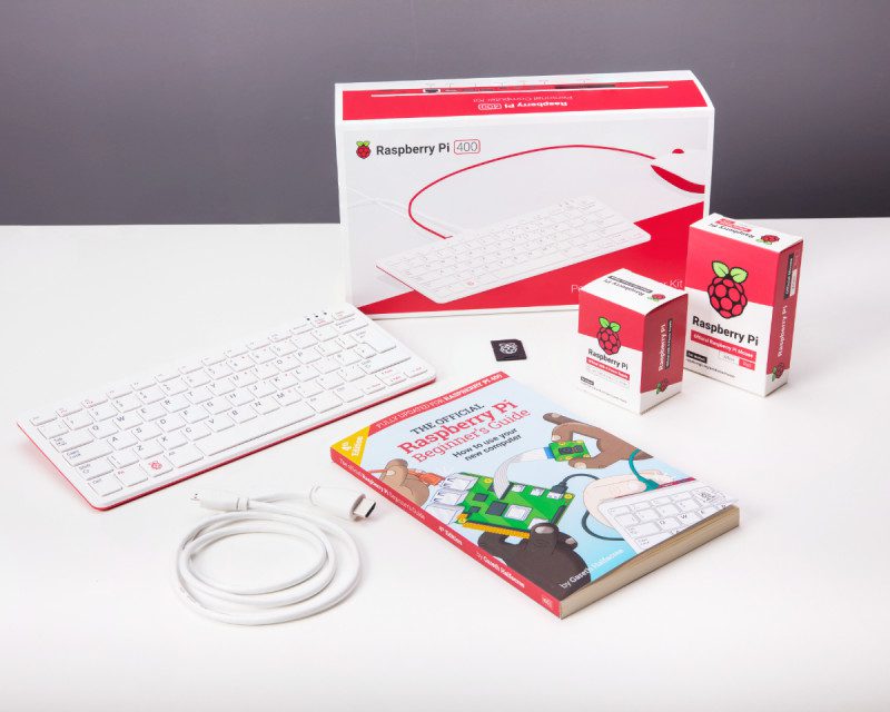
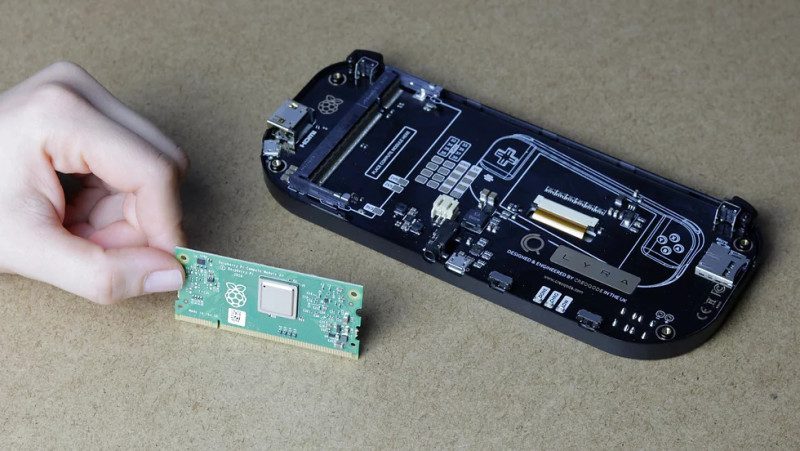
    A standard internal DVD-ROM drive is perfect: this build used a 2008 Sony NEC Optiarc AD-7203S SATA DVD-RW. Drives in this range are widely available for around £15, and this project is an excellent use for any old PC CD or DVD drives you might have lying around.

    To connect it, you’ll need either an external disc drive enclosure or SATA to USB adapter that takes external mains power. The kit photo above shows a StarTech USB2SATAIDE, which also supports IDE CD-ROM drives and hard disks. While this adapter is a little pricey at £42, similar hardware can be bought for about £20.

     This system can play DOS CD-ROM titles from disc as well as original games

    01 Connect your disc drive

    Plug the SATA data and power connectors of your adapter into the back of your DVD-ROM drive, plug the adapter’s USB connector into Raspberry Pi, and its mains adapter into a plug socket or power strip.

    This also works with externally powered drive boxes, which look better if you want a tidy and portable final product, but will require a little more assembly to the tune of a few screws.

    02 Overclock Raspberry Pi (Optional)

    Emulation can be demanding, so GPU and CPU overclocking makes sense, although it’s not absolutely necessary for this project. In a Terminal, type:

    https://www.libretro.com/index.php/category/retroarch-disc-project/

    And add the following lines:

    over_voltage=6
    arm_freq=1750
    gpu_freq=700

    These were stable during testing, but if Raspberry Pi fails to boot, power-cycle it and hold down SHIFT to boot into recovery mode. Then knock the settings down a bit. Here is further information on overclocking Raspberry Pi 4. If you overclock, you should use a stand or, better still, an active or passive cooling case. A FLIRC Raspberry Pi 4 Case worked well here.

    The source code may be lost forever, but you can still play Silent Hill in its original glory – complete with tank controls

    03 Enable OpenGL

    We’ll want OpenGL support for some emulators, such as PCSXR, In a Terminal, enter:

    https://flirc.tv/more/raspberry-pi-4-case

    Select Advanced Options &gt; GL Driver &gt; GL (Fake KMS), then exit
    and allow the system to reboot. Open /boot/config.txt and make sure the following option is present and not commented out:

    dtoverlay=vc4-fkms-v3d

    04 Drop your resolution

    Dropping your display resolution is an easy way of improving emulator performance. If you’re using a standard 1920×1080 widescreen monitor, you won’t need that resolution to play older games. Open the menu and go to Preferences > Screen configuration and set your resolution to 720×576 (or 640×480) if you either have a 4:3 display or can live with a bit of screen stretching in exchange for smooth full-screen graphics. Choose 1280×720 if you don’t mind playing in a window on emulators that can’t do aspect ratio correction.

    05 Connect an elderly TV (Optional)

    A 4:3 aspect ratio display is ideal here, and older display tech has the edge for 1990s console and computer games, too. Using a CRT TV rather than a modern LCD flatscreen can improve graphical quality as sprite and even 3D graphics of the era were optimised to work with the display artefacts of CRT.

    To control fixed‐path disc mounting for DOSBox using pmount, you’ll have to disable the File Manager’s default volume management behaviour

    Raspberry Pi supports composite video out. Connect a 4-pole 3.5mm AV cable to the 3.5mm port on Raspberry Pi and connect the other end to your TV. Using a composite to SCART adapter can improve picture stability. Note that Raspberry Pi’s 4-pole connector expects video to be connected to the sleeve and ground to ring 2, so ensure that you use a fully compatible cable. The wrong cable selection can result in non-functional sound, misordered cables, or even damage to your hardware.

    06 Output composite video (Optional)

    If you’re using a typical 4:3 PAL TV, make the following changes to /boot/config.txt to correctly position your display – small alterations may be required for different models. disable_overscan=0
    overscan_left=16
    overscan_right=16
    sdtv_mode=2 In a Terminal, enter:

    sudo raspi-config

    then go to Advanced Options, Pi 4 Video Output, and Enable analogue TV output. Finish and reboot.

    07 Mount a CD in DOSBox

    If you’ve been following these tutorials, you may already have DOSBox or DOSBox-X installed. If not, at a Terminal:

    sudo apt install dosbox
    dosbox

    To mount a disc at the DOS prompt, type:

    mount D /media/YourDiscName/ -t cdrom -usecd
    0 -ioctl

    To unmount a disc in DOSBox, type:

    mount -u D

    By default, each individual disc has to be manually mounted in DOSBox, as mount point names are automatically generated based on the volume name of the disc. This can be a problem if you need to swap DOS CDs during play or installation.

    08 Create a fixed mount point

    If you’re going to be playing on a PAL CRT television, you’ll need a 720×576 full-screen resolution

    To work around this, we can use the

    pmount

    command. From the Terminal, let’s first make sure it’s installed and then configure it:

    sudo apt install pmount
    sudo mousepad /etc/pmount.allow

    Add the following line to the file, then save and exit:

    /dev/sr0

    On the desktop, open File Manager. Go to Edit > Preferences > Volume Management and untick all the Auto-mount options. Reboot Raspberry Pi.

    09 Mount and swap CDs

    Now, to mount a disc, insert it, open a Terminal window and type:

    pmount /dev/sr0

    To unmount it:

    pumount /dev/sr0

    Repeat the first

    pmount

    command to mount a new disc. Now, every disc will have a fixed mount point of

    /media/sr0/

    This means that, in DOSBox, you’ll just need to mount

    D/media/sr0/

    once. When you want to swap discs, whether at the DOS prompt or in-application, hop over to a Linux Terminal window, run through the

    pmount

    commands and then, back in DOSBox, press CTRL+F4 to update cached information about your mounted drives.

    10 Play original discs

    Getting PCSXR’s disc drive settings right is critical. Too high a speed or too fast a spindown can make games judder and stutter

    PCSXR – the R stands for either Reloaded or ReARMed, depending on which version you’re using – is an open-source emulator. It also has a genuinely good emulated bios, so you don’t need to download anything dodgy to make it work. The desktop version works best for original discs. Open a Terminal and type:

    sudo apt install pcsxr

    It can run games including Final Fantasy VII, Silent Hill, GTA, Sheep, and Resident Evil either perfectly or with only minor errors, but you’ll have to adjust some settings first.

    11 Configure PCSXR’s graphics

    Go to the Configuration menu and select Plugins &amp; BIOS. From the Graphics pull-down. Select OpenGL Driver 1.1.78. Click on the window icon directly to the right of the pull-down.

    This build included an internal PC DVD-ROM drive, an externally powered SATA- to-USB adapter, a composite video out cable and SCART adapter, a heat-sink case, and controller

    Starting with the Windows options tab, assuming you’re using the PAL resolution we configured, enter a width of 720, a height of 576, and tick the Fullscreen box. On the Textures tab, set Quality to Don’t care, Filtering to None, and HiRes Tex to None.

    In the Framerate tab, ensure that Use FPS limit is ticked and set to auto-detect. Moving to the Compatibility tab, select Standard offscreen drawing, a Black framebuffer, and Emulated Vram for framebuffer access. Make sure the Mask bit and Alpha multipass boxes are ticked.

    In the Misc tab, tick Untimed MDECs, Force 15 bit framebuffer updates, and Use OpenGL extensions. The Special game features tab includes game-specific options, such as battle cursors for Final Fantasy VII. Click Okay to save your changes.

    12 Configure PCSXR’s sound and CD-ROM

    Click on the window icon next to the Sound pulldown in the configuration window. Set Volume to Low, Reverb to Off, and Interpolation to None. Unsick everything except Single channel sound. Click Close, then open the CD-ROM settings. Set read mode to Normal (No Cache), Spindown time to 2 minutes, Cdrom Speed to 2min, and tick Emulated subchannel read. While you may need to adjust these settings for individual games or experiment with higher resolutions, this combination allows the vast majority of titles to run reasonably smoothly from their original discs. To test this, insert a disc into the drive, wait for it to load, then click on the CD icon at top left of the PCSXR window.

    Catch KJ on Twitter @KJOrphanides

  • pi-top [4] DIY Edition

    pi-top [4] DIY Edition

    Reading Time: 3 minutes

    It has considerable heft to withstand the rigours of the classroom. We measured the base
    unit at 100×130×35mm and weighed it in at 397g.The GPIO sockets (with BCM numbering) break out to the top of the case alongside a small
    120×64 OLED display and four control buttons, a built-in battery, and a speaker. You gain a second USB-C port for the upcoming pi-top Bluetooth Keyboard and FHD Touch
    Display
    . Which promises to transform pi-top [4] into a touchscreen laptop.

    Battery and screen

    Add your own Raspberry Pi 4 to the pi-top [4] DIY Edition

    It’s the only case we’ve seen that contains a built-in battery and display. Making pi-top [4]
    good for mobile use and also acts as power redundancy. It takes around an hour to charge
    and lasts for around five hours of use. The small 128×64 OLED displays information on the battery level, CPU load, and network
    connection. We were glad to discover an OLED and Button API in the documentation. The ‘ptoled’ module enables you to draw text, images and GIFs to the display, and plot and draw shapes.

    Built-in cooling

    pi-top [4] includes a fan that automatically adjusts its speed according to the CPU
    temperature. We tested it with Stressberry and found that pi-top [4] idled at 35°C, maxing out under stress at 45°C (with an ambient temperature of 14°C). We overclocked it and ran pi-top [4] at 2GHz and the temperature maxed out at 56°c. At all
    times the fan remained at a constant low non-intrusive spin, with speed controlled by the pi-top Hub. Reconnecting the fan to a second jumper enables manual control.

    Installation

    A built-in battery provides around five hours of portable use

    Installing Raspberry Pi inside pi-top [4] took around five minutes. Wil Bennett, pi-top’s
    director of technology, has a YouTube video that walks you through the installation process. pi-topOS Solaris is a feature-packed operating system built on top of Raspberry Pi OS (32-
    bit) ‘Buster’. It’s possible to use stock Raspberry Pi OS and control the pi-top hardware. We used this script:

    echo "deb http://apt.pi-top.com/pi-top-os sirius main contrib non-free" | sudo tee /etc/apt/sources.list.d/pi-top.list &> /dev/null curl https://apt.pi-top.com/pt-apt.asc | sudo apt-key add sudo apt update sudo apt install --no-install-recommends -y pt-device-manager pt-sys-oled pt-firmware-updater sudo reboot

    We had to install a firmware update to get the stock Raspberry Pi OS working; pi-top
    assures us the final version will ship with the firmware installed. On the whole, we really like pi-top [4]. A lot more than we expected. The price remains a
    hurdle, costing four times more than the Argon One. However, it has a range of unique features that make a compelling case for the additional cost and there’s no arguing with the build quality.

  • Raspberry Pi 400 specifications, benchmarks, and personal computer kit

    Raspberry Pi 400 specifications, benchmarks, and personal computer kit

    Reading Time: 6 minutes

    Raspberry Pi 400 packs a measurable speed boost over Raspberry Pi 4, thanks to a clever passive cooling system which offers enough headroom for a processor jump to 1.8GHz. Join us as we dive into the latest, and most impressive, Raspberry Pi ever made.

    Raspberry PI 400 specifications

    • Price: £65 / $70 (Raspberry Pi 400), £93.00 / $100 (Raspberry Pi 400 Personal Computer Kit)

    • SoC: Broadcom BCM2711C0 quad-core A72 (ARMv8-A) 64-bit @ 1.8GHz

    • GPU: Broadcom VideoCore VI

    • RAM: 4GB LPDDR4 SDRAM

    • Networking: 2.4 GHz and 5 GHz 802.11b/g/n/ac wireless LAN, gigabit Ethernet

    • Bluetooth: Bluetooth 5.0, Bluetooth Low Energy (BLE)

    • GPIO: 40-pin GPIO header, populated

    • Storage: microSD

    • Ports: 1× USB Type-C power input, 2× micro-HDMI 2.0, 1× USB 2.0, 2× USB 3.0, 1× RJ45 Ethernet, 1× Kensington locking slot

    • Cooling: Built-in passive heatsink

    • Dimensions: 286mm × 122mm × 23.7mm, 385g

    Where to buy Raspberry Pi 400

    Click here for a full list of Raspberry Pi 400 resellers

    Raspberry Pi 400 Personal Computer Kit

    You can buy Raspberry Pi 400 on its own, or as part of a Personal Computer Kit bundle with all the accessories you need. Inside the box you’ll find:

    Raspberry Pi 400 Personal Computer Kit

    Meet Raspberry PI 400

    On the first inspection, Raspberry Pi 400 is deceptively similar to the Raspberry Pi keyboard and hub. It features the same high-quality keyboard.

    Raspberry Pi 400 Front

    Around the back of Raspberry Pi 400

    The rear of Raspberry Pi 400 tells a different story, with an array of sockets and connectors. Inside Raspberry Pi 400 is hardware based upon Raspberry Pi 4, but with a different design to reposition all the connections.

    Raspberry Pi 400 sockets and connections

    40-pin GPIO header

    The 40-pin GPIO header is used to connect Raspberry Pi 400 to electronic devices and to experiment with electronics and coding. Look closely and you’ll see PIN1 and PIN40 imprinted on the case next to the first and last pin.

    Raspberry Pi 400 GPIO pins

    Using HAT hardware with Raspberry Pi 400

    Raspberry Pi 400 has the same 40-pin GPIO header as all current Raspberry Pi models. Only now it’s positioned on the rear of the case.

    You can connect HAT hardware directly to the 40-pin GPIO header, but it will be pointing backwards and down. A ribbon cable can be used to extend the GPIO pins and most will connect to Raspberry Pi 400 and extend with the pins facing upwards. You can pick up ribbon cables from The Pi Hut and other stores for around £3.

    Here we’re using a 40 Pin GPIO Ribbon Cable – Rainbow 150mm from The Pi Hut (£3).

    Raspberry Pi 400 with ribbon cable and Sense HAT

    Raspberry Pi 400 sockets and connections

    Raspberry Pi 400 sockets and connections

    microSD socket

    This push-click microSD socket acts as the main drive. A 16GB microSD card with Raspberry Pi OS pre-installed is included in the box. Ensure the microSD card is inserted and power up to start Raspberry Pi 400.

    2x micro HDMI

    Two micro HDMI connectors are used to connect Raspberry Pi 400 to up to two 4K monitors. Raspberry Pi tell us they’re „happy with the micro HDMI connector form factor“ and there would be no way to support dual display with full-size connectors. A micro HDMI to HDMI cable is included in the Raspberry Pi 400 personal computer kit.

    USB-C power

    Raspberry Pi 400 is powered via this USB-C Power connection using a Raspberry Pi 15.3W USB-C Power Supply (included in the Raspberry Pi 400 personal computer kit).

    USB 3.0

    Two USB 3.0 sockets are used to connect devices requiring fast throughput, such as external storage drives.

    USB-A 2.0

    A single USB 2.0 socket is provided; typically it is used with the included mouse.

    Gigabit Ethernet

    Gigabit Ethernet provides a fast direct network connection.

    Kensington lock socket

    Secure Raspberry Pi 400 to a table with the security lock socket.

    The Raspberry Pi 400 with a mouse, USB-C power, and HDMI cable attached

    Inside Raspberry Pi 400

    Built entirely into the keyboard, Raspberry Pi 400 keeps clutter to a minimum while simplifying setup – and if you buy the bundled version, it even comes with a Raspberry Pi OS microSD card pre-installed to get you up and running as quickly as possible.

    Inside Raspberry Pi 400

    The underside of the case, which clips in place using no screws, includes two ventilated sections to let the built-in heatsink cooling system breathe. A QR Code with the serial number is included in case you ever need to contact support.

    Inside Raspberry Pi 400, the custom heatsink takes up almost the entire casing. Connected to the system-on-chip with a thermal pad, the heatsink works silently to keep Raspberry Pi 400 from thermally throttling. This enables the processor to run at a faster 1.8GHz base speed.

    Under the heatsink, the printed circuit board uses a very different layout to previous Raspberry Pi models. Long and thin, the board has Ethernet hardware at its left, the USB and HDMI ports, the silver system-on-chip in the middle, the GPIO and keyboard connectors, and ends at the right with the wireless LAN and Bluetooth radio.

    Opening Raspberry Pi 400

    Open your Raspberry Pi 400 carefully! There are no screws, and it just clips into place all around the four sides of the body. Put a spudger (or a plectrum) between the two halves and slide until you feel a clip, then push to release; keep doing it until all clips have been freed and the two halves are apart. Remove the four screws to detach the heatsink.

    Benchmarking Raspberry Pi 400

    With 300MHz of extra clock speed, Raspberry Pi 400 is no slouch. Raspberry Pi 400 isn’t just an entirely new form factor and Raspberry Pi’s first integrated design: it’s also the fastest Raspberry Pi model ever released. A large metal heatsink, running almost the entire width of the casing, coupled with a roomier printed circuit board means Raspberry Pi 400’s system-on-chip ships clocked at 1.8GHz (one billion eight hundred million cycles per second) – up from Raspberry Pi 4’s 1.5GHz.

    The additional speed can be felt in everything from web browsing and image editing to running Python programs, and it doesn’t come at the cost of compatibility: Raspberry Pi 400 is fully compatible with all software and operating systems which work on Raspberry Pi 4, and older models too.

    It can also use less power: while the extra 300MHz means Raspberry Pi 400 draws more electricity than Raspberry Pi 4 under load, it finishes more quickly – and not needing an external USB keyboard means it uses less power at idle, too.

    For the majority of use-cases, Raspberry Pi 400 is now the machine to beat – but those working on embedded projects will find the more compact Raspberry Pi 4, with its Display Serial Interface (DSI) and Camera Serial Interface (CSI) ports and Power over Ethernet (PoE) capabilities, is still the go-to model.

    See also: Raspberry Pi 4 benchmarks

    Raspberry Pi 400 benchmark testing: Linpack (higher is better)

    Raspberry Pi 400 Linpack Benchmark

    Originally developed for supercomputers, this synthetic benchmark – ported to Raspberry Pi OS by Roy Longbottom – offers a look at best-case performance gains between models. Three versions of the benchmark are compared: Single Precision (SP), Double Precision (DP), and a Single Precision variant which uses the accelerated Arm NEON instructions available since Raspberry Pi 2.

    The extra speed of Raspberry Pi 400 makes it ideal for use as a desktop computer

    More benchmarks and engineering interview in The MagPi magazine issue #100

    We’ve got all the Raspberry Pi 400 information you could ask for in The MagPi magazine issue #100. On sale 26 November 2020. We have an in-depth interview with Eben Upton, CEO of Raspberry Pi and co-creator of the Raspberry Pi computer, and Simon Martin, Senior Principal Hardware Engineer at Raspberry Pi and designer of Raspberry Pi 400. Plus more detailed benchmarks and thermal testing of Raspberry Pi 400. Click here to subscribe to The MagPi and be sure not to miss a single issue.

  • Coffee Stirrer Camera

    Coffee Stirrer Camera

    Reading Time: 3 minutes

    “I’ve always loved pinhole cameras,” he tells us. “As I played with [them], I wondered if I
    could create a camera with hundreds of holes instead of a single point of light. That little
    idea virus took hold and eventually I found myself buying out Wal-Mart’s entire inventory of
    straws to test the idea.”

    He worked on the new camera for about a year, building three prototypes before arriving at
    the final design. “It’s funny how ideas seem like they will work in your head, but then when
    you build it in real life, things fail in unusual ways. For example, I went to great lengths to
    find the right surface for the image to be projected on inside the camera. At one point I
    debated destroying a large TV screen because I thought the matte glass of the TV was
    what would work. In the end, the material that worked best was ordinary wax paper. You
    just never know what will work until you experiment.”

    A Lego mounting system enables the HQ Camera (and an Olympus one) to be switched easily between prototypes

    Points of light

    Adrian explains the basics of how the camera works: “Think of a straw as a telescope.
    Look through it and you see a tiny part of the bigger picture. Stack thousands of straws
    and all those points of light add up to make a bigger picture. To capture the picture, the
    light from each straw lands on a semi-transparent surface inside the camera. I take a
    picture of that projection to get the final image.”

    Exposure times range from one to six seconds. “It’s a guessing game,” he says, “but the
    Raspberry Pi gives me a rough preview. As far as focus, the closer things are to the
    straws, the clearer they appear. Focusing comes down to getting as close to the subject as
    I can.”

    From left to right: The final camera, Prototype 1, Prototype 3, and Prototype 2

    Adrian reveals that when he heard about the new High Quality Camera earlier this year, he
    knew he had to try it. “I’ve always wanted to build my own digital camera. Old film cameras
    are easy to take apart and modify, but digital cameras are black boxes. Until Raspberry
    Pi’s High Quality Camera, it has been virtually impossible to build your own digital camera.
    Now the sky’s the limit.”

    A Lego mount enables easy attachment of the Raspberry Pi HQ Camera to any of the
    prototypes. “Once I screwed the 6mm Raspberry Pi lens to a 6×6 lego brick it made it
    easier to play with,” he says. “Lego is a quick and easy way to hold things in place as you
    are prototyping.”

    Public display

    Raspberry Pi is connected via an extended ribbon cable to the HQ Camera at the rear, which captures the projected image

    The public reaction to the camera has been very positive. “People’s first response is
    skepticism because it sounds like such a strange thing,” says Adrian. “But when they see
    the images it creates, they are won over. They realise it isn’t a gimmick, it’s a way to create
    images that are unlike anything else. And now that I am developing a following on
    Instagram (@ade3), it is rewarding to get kudos from people outside my small circle of
    friends and family.”

    The camera is ideal for portraits and eventually he wants to have a show where it can be
    in the gallery alongside the portraits taken with it. “Right now the camera still requires me
    to be very hands-on, but eventually I think I can to get it to a point where anyone could
    walk up to the camera and take a selfie. I like the idea of the camera existing on its own
    without me being there to operate it.”

  • Raspberry Pi Ultimate Wishlist in The MagPi magazine #99

    Raspberry Pi Ultimate Wishlist in The MagPi magazine #99

    Reading Time: 2 minutes

    Raspberry Pi Compute Module 4

    Compute Module 4

    Packing the power of Raspberry Pi 4 with an embedded form factor, Compute Module 4 is an incredible update for engineers and professionals. The most powerful Compute Module ever made packs a PCI Express lane, eMMC storage, and a quad-core ARM Cortex-A72 processor. We’ve got in-depth information about this new computer, plus benchmark tests and information about the new carrier boards.

    Project Showcase: Coffee Stirrer Camera

    Coffee Stirrer Camera

    Adrian Hanft has built an innovative camera that uses 23,248 coffee stirrer straws and a Raspberry Pi High Quality Camera to capture stunning, and unique, pictures. We talk to him about building experimental photography builds with Raspberry Pi.

    Build a CD-ROM disc system

    Build a retro CD-ROM console

    KG has been building a range of retro consoles for us in recent months, each one getting more and more advanced. This month KG delves into the world of CD-ROM gaming and multimedia entertainment systems. Attach a CD/DVD drive to your Raspberry Pi and get ready to (re)discover a world of classic entertainment.

    Raspberry Pi Holiday Projects

    Holiday projects for a festive home

    Get ready for the holidays with our guide to decorations, lights, sound, remote control, glitz and glamour. We’ve put together a selection of fantastic community projects that you can use to bedeck your home for the festive season.

    Stellina review

    Stellina review

    Rob goes hands-on with a high-powered Raspberry Pi telescope. Stellina whirred and tracked across the night sky and took photographs of Saturn for us. It’s a magical piece of kit.

    Christina Foust interview

    Christina Foust interview

    One of the creators of the current Digital Making at Home streams tells us how she went from teacher to a different kind of teacher.

  • Win one of three PiBoy DMG kits!

    Win one of three PiBoy DMG kits!

    Reading Time: < 1 minute

    Subscribe

  • CubeSat dual-redundant flight computer

    CubeSat dual-redundant flight computer

    Reading Time: 3 minutes

    The University of Surrey student got the chance to work on a live CubeSat project with Surrey Space Centre, drawing on his undergraduate dissertation research. The AAReST(autonomous assembly of a reconfigurable space telescope) mission he worked on takes a modular approach to setting up a large-scale telescope in space. Its dual-redundant flight computer is equipped with two Compute Modules. Alex worked on its PCB (printed circuit board). 

    Raspberry Pi Compute Modules being tested. In use, an embedded microcontroller continuously monitors the system state of health to detect hardware faults

    Taking the helm 

    The project began in 2014, soon after the launch of the original Raspberry Pi Compute Module. This made a CubeSat board with redundant devices viable. “Redundancy is a common way to increase the reliability of space hardware. It has been used in the computers of Mars Rovers and the Space Shuttle,” Alex notes. “The idea is that if one system fails or becomes unresponsive, another can take over and continue its task.” This project was covered on the Raspberry Pi blog back in 2015

    Alex has been working on its fourth iteration. AAReST will use “a WiFi inter-satellite link to allow multiple spacecraft to rendezvous,” he explains. “Imagine flying into space one day and being able to connect to a satellite from your phone to conduct maintenance activities.” 

    Raspberry Pi works well because of its low cost and compact size. It’s a good alternative to the significant expense of a ‘radiation-hardened’ device that can withstand the extreme temperature of near space. “Raspberry Pi has many attractive characteristics for a COTS (commercial, off the shelf) flight computer,” says Alex. “It is low-cost and compact, more powerful than comparable microcontrollers, and has excellent support from the electronics and hobbyist community.

    “From an engineering perspective,” he adds, its “self-contained processor system can be integrated into an application without needing to worry about hard-to-implement supporting components.

    “The Compute Module’s edge connector gives access to the GPIO, USB, and camera interfaces, providing the flexibility to directly integrate a Raspberry Pi into another application.”

    Built-in redundancy

     Alex began with a partially completed blueprint from a previous student, but says this was largely a “clean sheet project”. Having been tasked with adding a cross-switched Raspberry Pi camera function and improving the system monitoring and control, he realised an integrated USB WiFi chipset would be beneficial. The Compute Modules run identical images of Raspberry Pi OS Lite (32-bit). In future, custom software code will run the dual-redundant code, possibly using Docker.

    “I needed a stable software platform for running basic benchmarks and interacting with the system. Both Compute Modules run identical images of Raspbian Buster Lite, with modified device tree blobs to initialise all required GPIO and buses on the right pins. During testing, pigpio was used to access the functions of I2C and UART buses.”

    Alex explains, “The CubeSat flight computer includes an MSP430 microcontroller to detect hardware failures and switch to the backup systems as soon as possible, to avoid permanent hardware damage. If a radiation hit caused a latch-up fault in the active Raspberry Pi, it would create a short-circuit path between the supply and ground.” The CubeSat would then switch to the other on-board Raspberry Pi.

    AAReSt concept showing how each CubeSat docks to form part of the modular satellite. Credit: AAReST collaboration

  • Raspberry Pi Compute Module 4 specs, benchmarks and testing in The MagPi magazine issue 99

    Raspberry Pi Compute Module 4 specs, benchmarks and testing in The MagPi magazine issue 99

    Reading Time: 3 minutes

    In The MagPi magazine issue #99 (on sale 29 October 2020), Gareth Halfacree takes a deep dive into Compute Module 4’s specifications and performs benchmark testing. Subscribe to The MagPi magazine to get all the in-depth information delivered to your door.

    The original Raspberry Pi Compute Module launched in April 2014 as a means to make it easier for engineers and professionals to put the power of Raspberry Pi into their designs. The compact Raspberry Pi Compute Module isn’t a single-board computer but a system-on-module (SOM) designed to be inserted into a carrier board.

    In 2016, Raspberry Pi Compute Module 3 and Compute Module 3 Lite offered higher specifications, switching to the same processor as Raspberry Pi 3. Compute Module 3+ boosted specifications still further. 

    And now Raspberry Pi Compute Module 4 and Compute Module 4 Lite make the jump to the same high-performance hardware as Raspberry Pi 4.

    These are the most powerful Compute Modules ever made. Eben Upton, CEO of Raspberry Pi trading and Raspberry Pi co-creator talks about Compute Module 4 in this Raspberry Pi blog post.

    Compute Module 4 mounted in Carrier Board

    Meet Raspberry Pi Compute Module 4

    Raspberry Pi Compute Module 4 uses a new form factor, swapping the SODIMM edge connector of earlier models to two high-density connectors on the underside. It’s a necessary change that brings all the features of the module to the Carrier Board.

    This requires a change in the pins which connect the module to the carrier board. While both systems have 200 pins, the new connector is smaller and adds compatibility with new Raspberry Pi features, like the second HDMI port and PCI Express.

    Compute Module 400 high-density connectors

    This means Raspberry Pi Compute Module 4 isn’t compatible with carrier boards designed for Raspberry Pi Compute Module 3.

    The new SoC improves performance, the additional RAM makes it possible to work with more complex applications, and high-speed PCI Express connectivity means carrier boards have access to significantly more bandwidth.

    Compute Module 4 specifications

    • SoC: Broadcom BCM2711C0 quad-core ARM Cortex-A72 (ARMv8-A) 64-bit @ 1.5GHz

    • GPU: Broadcom VideoCore VI

    • RAM: 1GB, 2GB, 4GB, or 8GB LPDDR4 SDRAM

    • Networking: Optional 2.4 GHz and 5 GHz 802.11b/g/n/ac Wi-Fi, Gigabit Ethernet PHY

    • Bluetooth: Optional Bluetooth 5.0 and Bluetooth Low Energy (BLE)

    • GPIO: Carrier board dependent

    • Interfaces: PCI Express, 2× DSI, 2× CSI, 2× HDMI

    • Storage: External (CM4 Lite); on-board 8GB/16GB/32GB eMMC (CM4)

    • Ports: Hirose U.FL antenna connector, 2× 100-pin high-density connectors

    • Dimensions: 55 mm × 40 mm × 4.5mm, 12g (exc. carrier board)

    Compute Module 4 Carrier Board

    Compute Module Carrier boards

    Unlike other models, Raspberry Pi Compute Module 4 has no connectors of its own – bar the U.FL antenna connector and the two high-density connectors on the underside. Instead, it relies on a carrier board – and the features available will depend on what features the carrier board breaks out.

    Raspberry Pi Compute Module 4 Input/Output (IO) Board is an open-source design. It is designed to help developers get started: it brings out features including two full-size HDMI ports, Gigabit Ethernet, two USB ports, a 40-pin general-purpose input/output (GPIO) header, a Power over Ethernet (PoE) header, two DSI ports, two CSI ports for cameras, a PCI Express slot, and more.

    Compute Module 4 and Compute Module 4 Carrier Board

    Other carrier boards compatible with Raspberry Pi Compute Module 4 may be specialised for particular tasks, offering specific features or adding extra hardware of their own. Designers can tailor the carrier board to a particular task, but all carrier boards will be mechanically compatible with all Raspberry Pi Compute Module 4 models.

    The MagPi issue #99 is on sale 29 October with in-depth benchmark testing for Compute Module 4. Buy your copy from the Raspberry Pi Press Store or subscribe now to get The MagPi magazine delivered to you door every month.

  • Build a multi-room audio system with Raspberry Pi

    Build a multi-room audio system with Raspberry Pi

    Reading Time: 6 minutes

    Kit you’ll need

    Mopidy Music System

    Hi-Berry DAC+ Zero

    Case (optional)

    See also: Build a home music system with Raspberry Pi and Make a audio system with Mopidy

    Tip! Choose your DAC

    There are a wide range of digital-audio convertors out there catering for every budget from £12 to thousands – choose wisely.

    Going multi-room

    Sure, playback from our Mopidy setup is great, but you don’t want to be carrying that setup around the house. With Snapcast we can play music anywhere in perfect sync so you can wander around your home without interruption. This clever piece of open-source software sends out audio in ‘frames’, each one with a time code attached. Any device that’s part of the stream matches the frame’s time code to its own internal clock to ensure playback happens at the same time, providing in-sync audio. The only downside is a short delay in starting playback as everything syncs up.

    Snap to it

    Before we can add Snapcast clients, our original Mopidy needs to become one itself, so it can keep in sync with everything else. We start by installing the Snapcast client and server on the same machine (it’s effectively streaming to itself). Enter the following on the command line to download the client:

    wget https://github.com/badaix/snapcast/releases/download/v0.20.0/snapclient_0.20.0-1_armhf.deb
    sudo dpkg -i snapclient_0.20.0-1_armhf.deb

    If you get an error here, run this to fix it:

    sudo apt -f install

    This automated install sets everything up and will restart the service on reboot.

    Snappy service

    We have the client running on your Mopidy system, but nothing to serve music. So, now install the server:

    wget https://github.com/badaix/snapcast/releases/download/v0.20.0/snapserver_0.20.0-1_armhf.deb
    sudo dpkg -i snapserver_0.20.0-1_armhf.deb

    This will also restart on boot. The client will automatically find the server as its local. Now tell Mopidy to send its audio stream to the Snapcast server instead of the DAC.

    sudo nano /etc/mopidy/mopidy.conf

    Change…

    output = autoaudiosink

    …to (on one line):

    output = audioresample ! audioconvert ! audio/x-raw,rate=48000,channels=2,format=S16LE ! wavenc ! filesink location=/tmp/snapfifo

    Now restart Mopidy:

    Tell Iris about it

    Iris comes with full control over the Snapcast system. After restarting Mopidy, go to the Iris interface and into Settings. You’ll see a Snapcast icon. Click on it and then click ‘Enable’. You should see a ‘Connected’ message appear. There will also be a group which represents your local Mopidy setup. Click the group to rename it to something memorable. Before proceeding further, make sure that playback still works. It’ll take a second or two longer to start as Snapcast syncs up, but should otherwise be unaffected. If it works well, your local Mopidy setup is complete.

    The HiFiBerry DAC is an entry-level digital-to-analogue convertor that provides much higher quality than the standard audio out from a Raspberry Pi

    Just add clients

    Your system is now in effect streaming to itself, which means it can play in sync with other devices, so let’s add one. We’re using the HiFiBerry DAC+Zero, a great DAC for a small price. Start by connecting the DAC to a Raspberry Pi Zero W, ideally using standoffs to ensure a secure fit. Install Raspberry Pi OS Lite on this device as we’re going to be running it headless. Using raspi-config make sure you’ve configured wireless LAN and set a suitable hostname. Now update everything to the latest version using:

    sudo apt -y update && sudo apt -y full-upgrade

    Make some noise

    To enable the DAC+ Zero, get command-line access to your Raspberry Pi Zero W (using SSH or connect up a monitor and keyboard) and edit the main configuration file:

    sudo nano /boot/config.txt

    Near the end of the file, find the line reading:

    dtparam=audio=on

    Delete it (or comment out with a #) and add:

    dtoverlay=hifiberry-dac

    Save (CTRL+X) and reboot your computer. Once back up, connect the phono sockets on the DAC to an amplifier and test the output:

    aplay /usr/share/sounds/alsa/Front_Center.wav

    If everything is working well, a nice person will say “front centre”.

    The addition of this purpose-built case not only protects your project but also adds a bit of class

    Join the band

    To get streaming working, we now repeat the process for installing the Snapcast client. Start by downloading and installing the client:

    wget https://github.com/badaix/snapcast/releases/download/v0.20.0/snapclient_0.20.0-1_armhf.deb
    sudo dpkg -i snapclient_0.20.0-1_armhf.deb

    If you see errors at the end of the process with the line ‘dependency problems – leaving unconfigured’, run the following command:

    sudo apt -f install

    This will detect and install all the dependencies required and then finish configuration. Snapcast will be configured to automatically start on boot.

    The case includes access to the HDMI and USB ports, so you can connect a touchscreen monitor and use it as a Mopidy control centre

    Configure and test

    The Snapcast client is now running, but we need to tell it where the server is. Edit the configuration file:

    sudo nano /etc/default/snapclient

    Find the line that reads SNAPCAST_OPTS=““ and add your Mopidy server hostname as follows:

    SNAPCLIENT_OPTS="--host jukebox.local”

    Replace ‘jukebox.local’ with whatever you named your server. Save and exit, then restart the client:

    sudo systemctl restart snapclient

    In a web browser, open up Iris on your main server and go to Settings, then click on Snapcast. You should see a new group (something like ‘Group 8ec’); that’s your device.

    You can use Iris on any web device to control which group is listening to which stream

    Play, tweak, repeat

    Now try playing something from Mopidy with your new client hooked up to an amplifier or active speaker. Everything should be in sync. If not, you can adjust latency under your group settings to fine-tune the playback. At the bottom of the screen, you can click the speaker icon to control which devices are playing and set their individual volume levels.

    You can add as many Snapcast clients as you like. It’s a great use for an older Raspberry Pi and you don’t have to use a DAC, you can just use the standard audio/video jack to an active speaker. We built another client using Pimoroni’s Speaker pHAT and a battery for portable tunes.

    Add some Apple

    Snapcast supports multiple streams, allowing clients to switch between them. We can add Apple AirPlay 2 support as a Snapcast stream that runs alongside Mopidy. We can’t just install a package, though: we have to build and install Shairport Sync with the following commands:

    cd
    sudo apt install build-essential git xmltoman autoconf automake libtool libpopt-dev libconfig-dev libasound2-dev avahi-daemon libavahi-client-dev libssl-dev libsoxr-dev
    git clone https://github.com/mikebrady/shairport-sync.git
    autoreconf -fi
    ./configure --with-stdout --with-avahi --with-ssl=openssl --with-metadata
    make
    sudo make install

    Multistream!

    The final step is to configure Snapcast to enable Shairport Sync as a stream. Open up the Snapcast configuration file as follows:

    sudo nano /etc/snapserver.conf

    In the section starting [stream] you’ll see an entry starting stream =. Directly under there add the following line:

    stream = airplay:///shairport-sync?name=Airplay&devicename=Jukebox

    (You can change the names to anything you like.) Now restart everything:

    sudo systemctl restart snapserver.service
    sudo systemctl restart mopidy.service

    In Iris, go to the Snapcast settings and change the default stream to AirPlay. You can now push audio from iOS devices and Macs to your music system or any other Snapcast client.

    You can add as many Snapcast clients as you like and control their volume and latency from any smartphone or web browser

    Going further

    If you’ve played along and built this setup, you how have a pretty sweet audio player setup. The great thing about this project is the wider range of budgets and platforms for which it caters. You can reuse older hardware, upcycle speakers, and turn just about anything with a processor into a streaming client. You can also get HATs with pure digital S/PDIF or coaxial output so you can use an amplifier’s DAC if you prefer. How about using a USB audio capture device to stream audio around the house from your record player? As ever, it’s over to you.

    Tip! DAC’s not for me

    If you’re on a tight budget, you don’t need a DAC at all. The line-out found on board most Raspberry Pi computers will suffice for smaller projects.

  • Sonic Kayak

    Sonic Kayak

    Reading Time: 3 minutes

    After helping out on Sonic Bikes, a sound art project started by Kaffe Matthews, they thought about bringing the bikes to Cornwall, “but it’s a dangerous place for cycling with very few cycle paths and narrow roads,” Amber tells us, “so we started talking about making a version for boats.”

    With a background in wildlife conservation genetics, she thought it would be good to add some environmental sensors and try using it to gather underwater data. “So it’s gone from being a pure sound-art project on bikes, to something that has both sound-art and scientific purpose on kayaks. Kaffe’s now working on putting some of the environmental sensors onto the Sonic Bikes, so it’s going full circle.”

    Out on the water around Falmouth harbour, gathering environmental data from industrial areas, places where people live on houseboats, where there might be farm run-off etc

    Environmental sensors

    Each Sonic Kayak kit is equipped with four environmental sensors. Water temperature is measured using a digital thermometer, water cloudiness using a home-made sensor consisting of an LED and an LDR in a dark tube (the amount of light that hits the LDR is a measure of how cloudy the water is), underwater sound using a hydrophone, and above-water air pollution using a laser dust sensor.  There’s also a GPS unit to record the kayak’s geographical co-ordinates, which enables mapping of the environmental data gathered.

    Sounds based on the data are played in real-time through waterproof Bluetooth speaker to the kayaker. “This does two things,” explains Amber. “Firstly, it gives people a real connection to the underwater world that is otherwise very hard to understand. Secondly, if you are interested in gathering a particular type of data, for example pollution coming from a large boat, if you can hear when you are entering a polluted area then it allows you to follow that data and collect exactly what you need.”

    The system has also proven useful for people with visual impairments. “We’ve been working with an accessible kayak club to develop the system for navigation purposes, to allow people to kayak independently even if they have little or no sight.”

    Electronics and water

    The kit’s electronics – including a Raspberry Pi 3B and Arduino Nano – are housed in a Bopla Bocube plastic enclosure that fits into the rear of the kayak. The combination of electronics with salt water has proved problematic previously. “One of our earliest Sonic Kayak events was the British Science Festival in 2016, and on the second day the sea was very choppy and both kayaks capsized with the systems on them,” recalls Amber. “We watched all the electronics break apart and wash up on the beach, then almost instantly corrode due to the salt water, which was rather painful! Since then we’ve got very good with embedding electronics in resin, and using rubber seals for the sensor cables.”

    While the data gathered so far by the project is proof-of-principle, it may well be of interest to professional researchers. “This type of data is really hard to get, particularly for places close to cliffs or in tidal estuaries, where it’s difficult to take large research boats,” says Amber. “Our system also means you can get very fine-scale data, as opposed to the broader scale sea temperature data you get from satellites, or the data you can get from attaching sensors to buoys.”

    However, Amber says they’re more interested in getting it into the hands of people who want to use it to map their local environments. “We’ve started working on ways to visualise the data from the Sonic Kayaks on maps, and would love to make a portal where people can upload the data from their kayaking trips, and have it visualised automatically.”