Schlagwort: tech

  • An e-skateboard controller made from scratch with Arduino

    An e-skateboard controller made from scratch with Arduino

    Reading Time: < 1 minute

    An e-skateboard controller made from scratch with Arduino

    Arduino TeamJanuary 2nd, 2019

    Last June, Timo Brinschein bought a Qu4tro electric skateboard with hopes of using it for fun and commuting duties. Unfortunately, while the skateboard itself worked well, the remote had many shortcomings.

    Since replacing the skateboard’s controls entirely was out of reach, he instead settled on the “small” job of reverse engineering and swapping out the wireless controller for one of his own designs. 

    The resulting build uses an Arduino Nano as the brains of the device, along with the well-known nRF24L0+ module for wireless communication. Everything is housed inside a custom 3D-printed enclosure. 

    Code for the project is available on GitHub, and print files for the excellent control handle is on Thingiverse.

    Website: LINK

  • Electronoobs creates his own Bluetooth-controlled Daft Punk helmet

    Electronoobs creates his own Bluetooth-controlled Daft Punk helmet

    Reading Time: < 1 minute

    Electronoobs creates his own Bluetooth-controlled Daft Punk helmet

    Arduino TeamJanuary 2nd, 2019

    If you like electronic music, you’ve certainly admired Daft Punk’s glowing electronic helmets. While the originals are amazing, as shown in this Electronoobs tutorial, you can now make a very good replica for around $20 and 30 hours of print time.

    Print files for the helmet itself are based on this Thomas Bangalter build by the Ruiz Brothers, and similar to that one, a good amount of sanding and finishing was needed to give it a metallic look. 

    Electronoobs’ helmet features seven WS2812 RGB LED strips, all connected to an Arduino Nano. Everything is controlled over Bluetooth by a custom Android app made with the MIT App Inventor, along with a microphone that allows the visor to react to music.

    [youtube https://www.youtube.com/watch?v=RHGvi-HTYIs?feature=oembed&w=500&h=281]

    Website: LINK

  • High school play gets a simulated sports scoreboard

    High school play gets a simulated sports scoreboard

    Reading Time: 2 minutes

    High school play gets a simulated sports scoreboard

    Arduino TeamJanuary 2nd, 2019

    Maker “DJ’s Fantasi” is the technical director at his local high school’s theater arts program, and when the director of their winter production of Disney’s High School Musical requested a scoreboard prop, he excitedly set to work. 

    The resulting build consists of four 7-segment displays, lit up by strips of non-programmable LEDs. 

    Numbers on the device are shown with the help of an Arduino Mega, which takes input via a single-channel remote. Seven I/O pins are used to indicate each segment to be displayed, and another four multiplex the signal into the required four digits.

    While a more general input device could be used, this particular scoreboard was especially set up for this musical, sequencing through numbers that correspond to the performance on command.

    More details on this impressive project can be found here.

    Website: LINK

  • Build a tachometer for your metal lathe with Arduino

    Build a tachometer for your metal lathe with Arduino

    Reading Time: < 1 minute

    Build a tachometer for your metal lathe with Arduino

    Arduino TeamJanuary 2nd, 2019

    If you manage to get a small lathe in your home shop, it will likely come with a dial to adjust the speed, but it may not have a tachometer to tell you if it’s actually spinning at your desired setting. Rather than accept this imprecision on his model, hacker Tony Scarpelli designed his own non-contact tachometer using an Arduino Nano.

    The build is ingeniously simple, and mounts an infrared proximity sensor near gearing in the back of the lathe’s headstock. White paper is placed on this rotating surface, allowing the sensor to tell between this marker and the otherwise dark surface as it spins. Sensor pulses are recorded by the Arduino, which outputs RPM values on a small 16×2 LCD display.

    Website: LINK

  • Star Trek tricorder-style heart rate monitor

    Star Trek tricorder-style heart rate monitor

    Reading Time: < 1 minute

    Star Trek tricorder-style heart rate monitor

    Arduino TeamDecember 28th, 2018

    A heart rate monitor can be an important tool for tracking fitness and exertion levels, but what if you want something a bit more interesting style-wise? For a novel idea, be sure to check out the project shown below from “Taste The Code.”

    In it, Blagojce Kolicoski turns a handle used for launching rotating toys into something reminiscent of a tricorder from Star Trek.

    The build stuffs an Arduino, a pulse sensor, and a tiny OLED display into the handle, which conveniently already had accommodations for three AA batteries. This, along with the monitor’s I2C connection, meant that wiring everything up was quite simple. 

    Want to make your own? Instructions are available here, while code can be found on GitHub.

    [youtube https://www.youtube.com/watch?v=iVN3gXZ72P8?feature=oembed&w=500&h=281]

    Website: LINK

  • Create mesmerizing designs in the sand with this Arduino-controlled Zen table!

    Create mesmerizing designs in the sand with this Arduino-controlled Zen table!

    Reading Time: < 1 minute

    Create mesmerizing designs in the sand with this Arduino-controlled Zen table!

    Arduino TeamDecember 27th, 2018

    A sandbox game generally refers to an open world computer simulation, but Tim Callinan’s fall semester project takes things in a different direction—an actual sandbox controlled by an Arduino and gShield.

    Callinan’s Zen table is capable of producing complicated designs in the sand, using a single steel marble that appears to magically move across the surface by itself.

    Underneath the sand assembly is a stepper-controlled gantry that acts like a laser cutter or other CNC tool, dragging the marble around with a powerful magnet. The results are stars, rotating squares, and other kaleidoscopic patterns, beautifully edge-lit with a series of RGB LEDs.

    Several other classmates were involved in making this build a reality, including Mark Morello, who wired and programmed the device.

    [youtube https://www.youtube.com/watch?v=D8uCUroAHD4?feature=oembed&w=500&h=281]

    Website: LINK

  • Draw on an oscilloscope with Arduino

    Draw on an oscilloscope with Arduino

    Reading Time: 2 minutes

    Draw on an oscilloscope with Arduino

    Arduino TeamDecember 27th, 2018

    If you’ve ever wanted to plot shapes using an oscilloscope, YouTuber Electronoobs reveals the tricks in his latest video. In it, he draws a Christmas tree, along with a few other shapes, and while that holiday is now past, there’s always the 2019. Of course, you don’t have to wait, as these concepts can be applied to anything you like throughout the year!

    In the video, Electronoobs uses an Arduino Nano to produce PWM signals on two channels, filtering each of them with a capacitor and resistor. As he explains, shapes must be fairly simple, and end in the same place they started. Even with these restrictions, once the oscilloscope it turned to x/y plot mode and the signal is tuned in, the results are quite good.

    In this tutorial we will use two pins from the Arduino to create fast PWM signals. With a small filter, we change the amplitude of that signal according to the width of the PWM pulse. By that, we can draw shapes on the oscilloscope when in XY mode.

    Code for the project can be found in Electronoobs’ write-up here.

    [youtube https://www.youtube.com/watch?v=nlCADL5_g-I?feature=oembed&w=500&h=281]

    Website: LINK

  • OpenLH robot automates biological exploration

    OpenLH robot automates biological exploration

    Reading Time: 2 minutes

    OpenLH robot automates biological exploration

    Arduino TeamDecember 20th, 2018

    If you’d like an easy way to accomplish repetitive biological experiments, the OpenLH presents a great option for automating these tasks. 

    The heart of the system is the Arduino Mega-controlled uArm Swift Pro robot, which is equipped with a custom end effector and syringe pump. This enables it to dispense liquids with an average error of just .15 microliters.

    A Python/Blockly interface allows the OpenLH to be set up for creative exploration, and because of the arm’s versatility, it could later be modified for 3D printing, laser cutting, or any number of other robotic duties. 

    Liquid handling robots are robots that can move liquids with high accuracy allowing to conduct high throughput experiments such as large scale screenings, bioprinting and execution of different protocols in molecular microbiology without a human hand, most liquid handling platforms are limited to standard protocols.

    The OpenLH is based on an open source robotic arm (uArm Swift Pro) and allows creative exploration. With the decrease in cost of accurate robotic arms we wanted to create a liquid handling robot that will be easy to assemble, made by available components, will be as accurate as gold standard and will cost less than $1,000. In addition the OpenLH is extendable, meaning more features can be added such as a camera for image analysis and real time decision making or setting the arm on a linear actuator for a wider range. In order to control the arm we made a simple Blockly interface and a picture to print interface block for bioprinting images.

    We wanted to build a tool that would be used by students, bioartists, biohackers and community biology labs around the world.

    The OpenLH can be seen in the video below, bioprinting with pigment-expressing E. coli bacteria.

    [youtube https://www.youtube.com/watch?v=r-m2pXBq76A?feature=oembed&w=500&h=281]

    Website: LINK

  • An inexpensive device for analyzing roasted coffee beans

    An inexpensive device for analyzing roasted coffee beans

    Reading Time: 2 minutes

    An inexpensive device for analyzing roasted coffee beans

    Arduino TeamDecember 18th, 2018

    While you may not consider in detail how your coffee is roasted, those that produce it must pay special attention to make sure that the end product is consistent. Equipment to help analyze roasted coffee is normally quite expensive, but using a near-infrared sensor, Arduino Uno and Bluetooth module, Spencer Corry was able to make his own analysis setup.

    As shown in the video below, after calibration, beans are inserted into the analysis chamber using a tryer scoop. Light is shined onto the roasted beans, and the intensity of the reflected near-infrared radiation is analyzed in six different wavelengths. Intensity data is then transmitted via Bluetooth to a smart device, which can be used to make sure things are roasted perfectly.

    There has recently been a growth of small roasting companies offering custom in-house roasts. These companies are looking for less expensive alternatives to hiring and training a roast master or using the expensive Agtron Process Analyzer. The Degree of Roast Infrared Analyzer for Coffee Roasters, as described in this document, is meant to be an inexpensive means of measuring the degree of roast of coffee beans. The Degree of Roast Infrared Analyzer uses a tryer, a tool found on coffee roasters used to sample the coffee during roasting, to hold a sample of coffee. The tryer is inserted into the analyzer where the AS7263 NIR Spectral sensor is used to measure 6 different infrared bands (610, 680, 730, 760, 810, and 860nm). The reflectance measurements are transmitted via Bluetooth and can then be correlated to the degree of roast. The analyzer must first be calibrated by pressing a button on the inside of the box in which the PVC is used as a white balance as it has a relatively flat reflectance in the spectral range detected by the sensor.

    [youtube https://www.youtube.com/watch?v=NgYNQm1fcKk?feature=oembed&w=500&h=281]

    Website: LINK

  • A multi-matrix scrolling text display for absolute beginners

    A multi-matrix scrolling text display for absolute beginners

    Reading Time: < 1 minute

    A multi-matrix scrolling text display for absolute beginners

    Arduino TeamDecember 18th, 2018

    For this build, YouTuber DIY Perspective goes through the process of constructing a scrolling text display with two 8×8 matrices. 

    His instructions, along with an excellent video, go through the process from the very basics, including things that many would take for granted, like installing the Arduino IDE. For this reason, it could be a great introduction for those that are new to the maker electronics scene.

    The device is controlled via an Arduino Nano and can be powered by an 18650 battery or wall charger. While relatively simple electronics-wise, what really sets this project apart is the beautifully finished wooden enclosure. It’s held together with glue, and nicely sealed with a single screw!

    [youtube https://www.youtube.com/watch?v=lIQ_YTP7uC8?feature=oembed&w=500&h=281]

    Website: LINK

  • An Arduino-based rocket motor thrust test stand

    An Arduino-based rocket motor thrust test stand

    Reading Time: 2 minutes

    An Arduino-based rocket motor thrust test stand

    Arduino TeamDecember 17th, 2018

    If you enjoy model rocketry, you may wonder just what the thrust curve of the motors you’re using looks like. In order to answer that question, YouTuber ElementalMaker decided to construct his own test stand using an Arduino Uno coupled to a 10Kg load cell with an HX711 amplifier board. The test procedure is started with a little red button, and after warning LED blinks away for 10 seconds, it activates a relay and fires the motor under into the stand.

    The experimental setup seen in the video yields successful thrust curves for both a ½ inch and ¾ inch motor. As you might expect, the ¾ produces more thrust than its smaller cousin, though at 2,683 grams versus the ½ inch motor’s 658, it’s an impressive difference indeed. 

    The heart of the stand is a common load cell (the sort of thing you’d find in a digital scale) coupled with a HX711 amplifier board mounted between two plates, with a small section of vertical PVC pipe attached to the topmost plate to serve as a motor mount. This configuration is capable of measuring up to 10 kilograms with an 80Hz sample rate, which is critically important at this type of rocket motors only burn for a few seconds to begin with. The sensor produces hundreds of data points during the short duration of the build, which is perfect for graphing the motor’s thrust curve over time.

    Given such a small window in which to make measurements, [ElementalMaker] didn’t want to leave anything to chance. So rather than manually igniting the motor and triggering the data collection, the stand’s onboard Arduino does both automatically. Pressing the red button on the stand starts a countdown procedure complete with flashing LED, after which a relay is used to energize a nichrome wire “electronic match” stuck inside the motor.

    The project is based on a paper archived here if you’d like to examine the design.

    [youtube https://www.youtube.com/watch?v=-yq1EmTkBCs?feature=oembed&w=500&h=281]

    Website: LINK

  • Build a single-pixel scanning camera with an RGB sensor

    Build a single-pixel scanning camera with an RGB sensor

    Reading Time: 2 minutes

    Build a single-pixel scanning camera with an RGB sensor

    Arduino TeamDecember 15th, 2018

    Sensors like the TCS34725 from Adafruit can detect a single color. It stands to reason then, that if you were to aim this sensor at a multitude of points and record the resulting data, you could have a one-pixel camera. As seen here, Tucker Shannon decided to take this concept and run with it, constructing his own with an Arduino Uno and a pair of stepper motors.

    The device looks like something akin to some sort of auto-turret, and directs the sensor in a square spiral for image acquisition. The resulting pictures are certainly low-res, but good enough to pick out recognizable forms with a little imagination. 

    The color sensor tells the Arduino what color it “sees” at any given time. By pointing it at every single point within a field of view, I can record these colors and use them later to reconstruct an image.

    Using two stepper motors, the camera points the sensor at every “pixel” within the photo and records what it sees. It uses these values to “paint” a picture of whats in front of it!

    Components include: 1x Arduino Uno, 1x Adafruit RGB Color Sensor TCS34725, x2 BYJ-48 Stepper motor with drivers, x1 3mm OD aluminum tube, x20 M3x6mm fasteners. Alternatively a photoresistor can be used in place of the RGB sensor for black and white photos!

    Code for the project can be found on GitHub, and print files are on Thingiverse if you’d like to build your own!

    Website: LINK

  • Drone morphs into the perfect shape in mid-air

    Drone morphs into the perfect shape in mid-air

    Reading Time: < 1 minute

    Drone morphs into the perfect shape in mid-air

    Arduino TeamDecember 14th, 2018

    Drones come in many shapes and sizes, but for the most part their motor pods are fixed during flight. Inspired by the way birds can fold their wings, researchers from the University of Zurich and EPFL have come up with a quadcopter capable of changing motor orientation dynamically in mid-air. This allows the nominally X-shaped drone to fold itself into tight spaces, and even configure itself for optimal handling.

    Flight control is handled by an advanced Snapdragon quad-core computer, while the servos that actuate the motor arms are controlled using an Arduino Nano. 

    An interview about the project is available on IEEE Spectrum, while the Foldable Drone’s research paper, along with several more videos, can be found here.

    [youtube https://www.youtube.com/watch?v=jmKXCdEbF_E?feature=oembed&w=500&h=281]

    Website: LINK

  • Keep track your weekly tasks with Arduino and arcade buttons

    Keep track your weekly tasks with Arduino and arcade buttons

    Reading Time: 2 minutes

    Keep track your weekly tasks with Arduino and arcade buttons

    Arduino TeamDecember 14th, 2018

    All of us have daily tasks we need to perform, but what if you often forget whether you’ve done something, or simply need to give your child a little extra motivation? One great way would be Simon Prickett’s Arduino Task Tracker, inspired by Simone Giertz’s Every Day Calendar. 

    Prickett’s clean-looking device is built into an electrical junction box, which holds the guts, including an Arduino Uno inside. It also exposes eight arcade-style LED buttons on top.

    After you, or in this case Prickett’s son, complete a chore, press one of the seven green buttons. Once they are all lit, the Arduino Task Tracker produces a “victory roll” sequence. The eighth red button is then used to start the week over again. 

    Sound like something you’d like to recreate? Code and more info for the project can be found GitHub.

    [youtube https://www.youtube.com/watch?v=BcS5LLRLeBo?feature=oembed&w=500&h=281]

    Website: LINK

  • Arduino Mega is the brains of this ant-like hexapod

    Arduino Mega is the brains of this ant-like hexapod

    Reading Time: 2 minutes

    Arduino Mega is the brains of this ant-like hexapod

    Arduino TeamDecember 13th, 2018

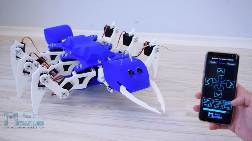
    Six-legged robots are nothing new, but if you’d like inspiration for your own, it would be hard to beat this 22 servo-driven, 3D-printed hexapod from Dejan at How To Mechatronics. 

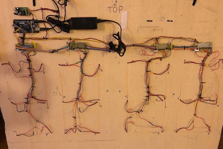
    The ant-inspired device features three metal geared servos per leg, as well as a pair to move the heat, another for the tail, and a micro servo to activate the mandibles.

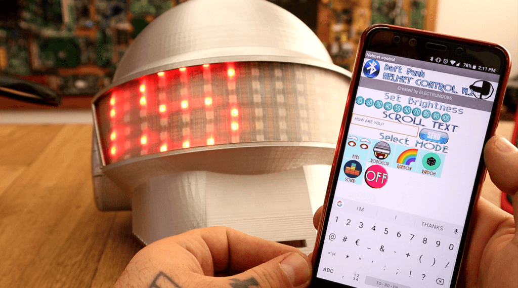
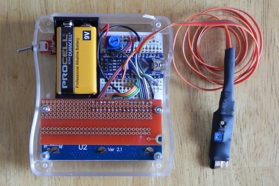
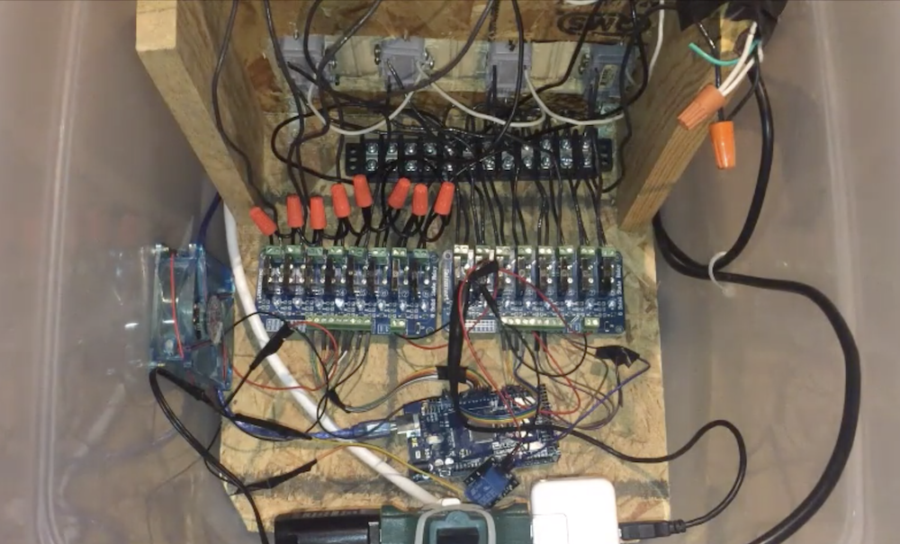
    To control this large number of servos, Dejan turned to the Arduino Mega, along with a custom Android app and Bluetooth link for the user interface. While most movements are activated by the user, it does have a single ultrasonic sensor buried in its head as “eyes.” This allows it to lean backwards when approached by an unknown object or hand, then strike with its mandibles if the aggressor continues its advance. 

    As the name suggests, the hexapod has six legs but in addition to that, it also has a tail or abdomen, a head, antennas, mandibles and even functional eyes. All of this, makes the hexapod look like an ant, so therefore we can also call it an Arduino Ant Robot.

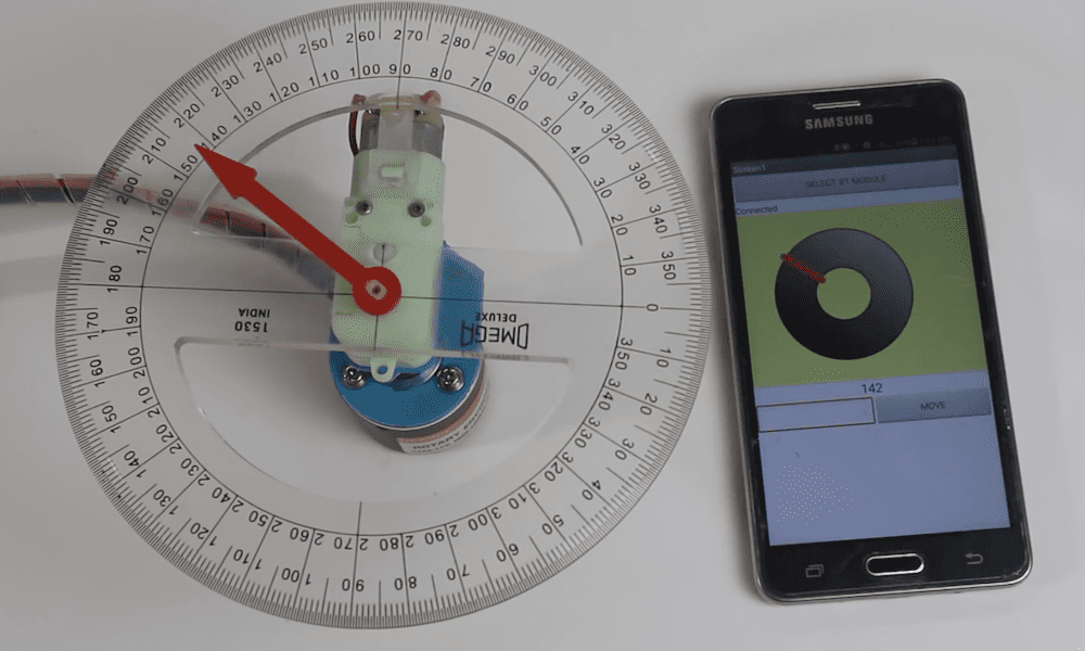
    For controlling the robot I made a custom-built Android application. The app has four buttons through which we can command the robot to move forward or backwards, as well as turn left or right. Along with these main functions, the robot can also move its head and tail, as well as it can bite, grab and drop things and even attack.

    You can see it in action and being assembled in the video below, and build files are available here.

    [youtube https://www.youtube.com/watch?v=bmoGfBe63ZA?feature=oembed&w=500&h=281]

    Website: LINK

  • Musical lighting pattern changes based on automatic analysis

    Musical lighting pattern changes based on automatic analysis

    Reading Time: 2 minutes

    Musical lighting pattern changes based on automatic analysis

    Arduino TeamDecember 12th, 2018

    LED strips reacting to sound is nothing new; however, Paul Shulman’s setup does things a bit differently. Instead of responding to the tune’s overall volume, one musical frequency is analyzed and averaged; if the intensity changes sufficiently on that particular frequency, the corresponding lighting effect is also changed. This avoids the problem of analyzing a music source that doesn’t necessarily change with the final output volume.

    A SparkFun Spectrum Shield is used for frequency separation. An Arduino handles signal analysis, which sends a change effect command to the lighting controller when needed. There’s also a wireless remote available to adjust the lighting manually. 

    This system was designed with the goal of having color-chasing LED effects that automatically sync with a hard music line. The color-chasing effects observed in the video are actually not synchronized to the music, but the changing of effects is. The system works well across many genres of music. This system is unique in that music volume does not matter. Many commercial implementations control lighting effects based off of overall volume intensity. This is problematic, as many people do not control final music volume with the source of the music (i.e. leaving your PC volume constant and controlling speaker volume instead.

    An additional feature of this system is that it contains a wireless remote and the ability to control the lights independent of the music. This allows for rapid light patterns at parties, and soothing ambient lighting at all other times.

    Code for the project is available in Shulman’s write-up, and the results can be seen in the demo video below. 

    [youtube https://www.youtube.com/watch?v=Akqn7_cqmlg?feature=oembed&w=500&h=281]

    Website: LINK

  • There’s no need to buy an electric screwdriver, just 3D print your own!

    There’s no need to buy an electric screwdriver, just 3D print your own!

    Reading Time: 2 minutes

    There’s no need to buy an electric screwdriver, just 3D print your own!

    Arduino TeamDecember 11th, 2018

    What do you do when you need to attach 400-500 screws for an upcoming project? If you’re “Progress Thailand” you simply create one yourself using a 9g micro servo modded for continuous rotation, an Arduino Nano, and some 3D printing!

    The build uses a small thumb joystick for proportional control, and can accommodate a small hand driver in addition to a bit by itself. Impressively, a functional prototype of the tool was produced in a single day, with the final(?) version appearing a couple of days later. 

    Hand and power tools are cheap, reliable, and easily accessible. But their production is still done in large centralized factories. 3D printing technology and cheap, open source electronics continue to improve bringing the decentralization of manufacturing one step closer.

    We are experimenting with different designs to see how close current 3D printing technology can bring us to production-quality tools you can buy in the store. We’re also experimenting to see what modifications we can make to store-bought tools to enhance and customize their use.

    While they note that the project isn’t meant to replace commercial screwdrivers at this point, it looks like a fun project with all the needed files available here to modify and improve things to your specifications!

    [youtube https://www.youtube.com/watch?v=2Dua8SScsfk?feature=oembed&w=500&h=281]

    Website: LINK

  • This one-button device can do many things

    This one-button device can do many things

    Reading Time: < 1 minute

    This one-button device can do many things

    Arduino TeamDecember 10th, 2018

    Bigger isn’t always better, as illustrated nicely by this device from YouTuber “Volos Projects.” It’s not only physically quite small, squeezing an Arduino into a 40x25x25mm aluminum enclosure, but uses an interface consisting of a single button (plus a power switch). Data output is handled via a similarly tiny 64×48 pixel OLED display.

    Regardless of its minuscule size and binary input method, it can still be utilized for a variety of functions, including as a stopwatch or counter, or even to play Flappy Bird. 

    Demonstration and build footage can be seen in the clip below, while a parts list, code, and electrical diagram can be found in the video’s description.

    [youtube https://www.youtube.com/watch?v=LC8FoGw8q8I?feature=oembed&w=500&h=281]

    Website: LINK

  • Mood-controlled RGB light wall

    Mood-controlled RGB light wall

    Reading Time: 2 minutes

    Mood-controlled RGB light wall

    Arduino TeamDecember 5th, 2018

    In the build shown below, Evan McMahon dares to ask the question, “Have you ever been disappointed by a mood ring?” While that might seem a bit random, the answer is a likely “yes” if you’ve ever worn one with the expectation of any sort of accuracy. Fortunately, he didn’t just pose the question, but also came up with a clever solution, using an array of lights under Arduino control.

    For the setup, McMahon uses the camera on his iPhone to take video of his smiling or frowning mug, and analyzes it with the help of Unity running on a computer to translate this into his apparent state of mind.

    This info is then sent to an Arduino Uno, which puts the programmable LED lights into dance mode if he’s happy, and makes them shine blue if he’s a bit blue himself!

    I made another thing! This time it’s a mood wall that reacts to your facial expressions. I made it out of an Arduino, poster board, disposable cups, NeoPixels, an iPhone X and a whole lot of cutting. The wall itself is driven by Unity, sampling animations and particle systems to make a final light show presentation.

    [youtube https://www.youtube.com/watch?v=Wip2i5hBl6o?feature=oembed&w=500&h=281]

    Website: LINK

  • Teenager automates his family’s holiday lights with an Arduino Mega

    Teenager automates his family’s holiday lights with an Arduino Mega

    Reading Time: 2 minutes

    Teenager automates his family’s holiday lights with an Arduino Mega

    Arduino TeamDecember 5th, 2018

    As first reported by the Des Moines Register, this year 14-year-old Josiah Davenport decided to animate 3,500 Christmas lights on his family’s home with the help of an Arduino Mega. The lighting pattern is synchronized with the Trans-Siberian Orchestra’s “Wizards in Winter,” which passersby can listen to by tuning in to 89.5 FM on their car radios. 

    This ambitious installation was started back in July, and took around 100 hours of research, programming, and assembly. How the lights look at night can be seen in the first video below, while the second and third outline how everything was assembled.

    Davenport notes that it’s been a fun endeavor, but is happy to see it come together, hoping that it brings a smile to people’s faces this holiday season! You can read more about the project in his local newspaper’s article here.

    [youtube https://www.youtube.com/watch?v=vxUUntIQnxo?feature=oembed&w=500&h=281]

    [youtube https://www.youtube.com/watch?v=36QBi99YWI8?feature=oembed&w=500&h=281]

    [youtube https://www.youtube.com/watch?v=F-U2Mf011y8?feature=oembed&w=500&h=281]

    Website: LINK

  • A useful Christmas tree water level indicator

    A useful Christmas tree water level indicator

    Reading Time: 2 minutes

    A useful Christmas tree water level indicator

    Arduino TeamDecember 3rd, 2018

    It’s that time of year again, when many the world over chop down a tree, then insert it into some sort of water dish to keep it green for a month or longer. This normally works out well, but means that someone has to keep it hydrated, climbing under sharp branches to intermittently check the water level.

    As originally seen on Reddit, this is a perfect job for Arduino, and with some very simple wiring, maker “Boskovitch” created a clever setup that shows water levels with three blue, yellow, and red LEDs. A depth sensor in inserted into the water, which feeds analog readings to an Arduino Nano that is used for control.

    Threw this together last night for my dad. He’s very anal about keeping his tree healthy, and he gets on his stomach and sticks his hand in the base to check the water level a couple of times a day. So I threw this together so he doesn’t have to crawl under the tree anymore. After the semester is over I might add an automatic watering system with a solenoid valve and gravity feed.

    Want to recreate this setup for your own Christmas conifer? Check out Boskovitch’s write-up here.

    Website: LINK

  • Simple PID control intro device

    Simple PID control intro device

    Reading Time: < 1 minute

    Simple PID control intro device

    Arduino TeamDecember 3rd, 2018

    You may have come across the term “PID control,” and while this proportional-integral-derivative control method does a great job of smoothing out oscillations, where does one get started? 

    One solution would be Mr Innovative’s demo device, showcased in the video below. In it, a DC gear motor is able to smoothly rotate an arrow overlaid on a protractor by a certain number of degrees.

    Input is via a Bluetooth smartphone interface, and an encoder is used for feedback to the commanding Arduino Uno. Everything is fastened together by 3D-printed parts, and if you’d like to try your own PID experiment, code and print files are linked in the video description.

    [youtube https://www.youtube.com/watch?v=K7FQSS_iAw0?feature=oembed&w=500&h=281]

    Website: LINK