It is probably well known by now that COVID-19 can cause serious side effects in people that last for months at time, meaning that recovering from the disease can be an arduous process. Some symptoms include trouble breathing, heart inflammation, and blood clotting, so being able to track these conditions as they progress is vital to ensuring ongoing safety for a patient. In response, Kamrul Hussain created the Vital Care project and entered it into element14’s Design for a Cause 2021 contest, where makers were challenged to use the Arduino Nano 33 IoT in some way for the good of humanity.
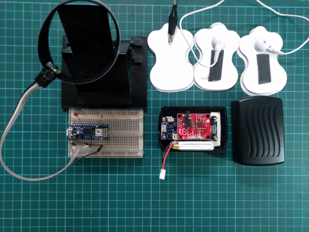
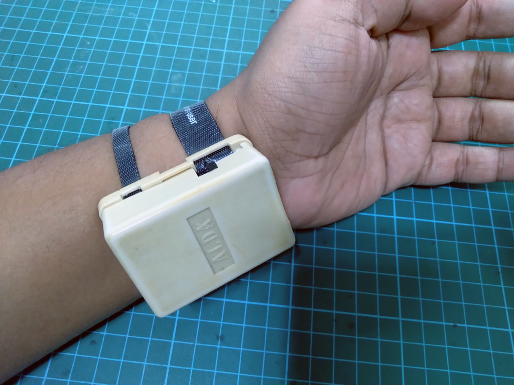
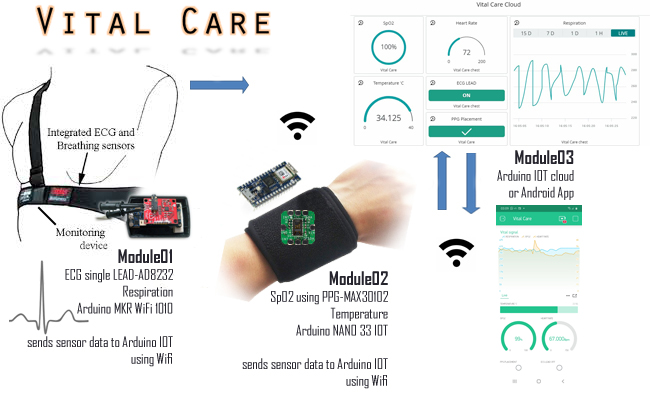
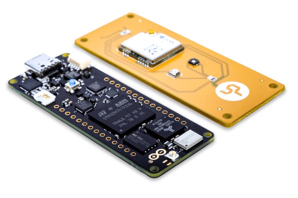
Hussain’s project implements a pair of sensors to measure various bodily functions: an AD8232 module for measuring heart activity and a MAX30102 for tracking oxygen saturation over time. The former board is connected to a MKR WiFi 1010, which relays heartbeat data to an Arduino Cloud dashboard. The latter module sits in a wrist-mounted enclosure and senses the level of oxygenated blood. This data is fed into a Nano 33 IoT and then sent to a dashboard as well.
When these two devices were combined into a single project and had their data streams fed into a single app, both the accuracy and breadth of the vitals data taken were greatly increased over what could be achieved in a doctor’s visit.
You can read more about the Vital Care project, which was named a runner-up in the contest, here in Hussain’s blog posts.
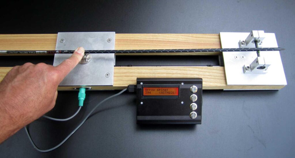
Repeatability requires consistency. This principle even applies to archery. If you want to hit the bullseye on every shot, you have to draw the string with consistent force, keep your stance consistent, and so on. You also want your arrows to be as consistent as possible. One major factor that goes into an arrow’s consistency is the stiffness of the shaft, called the spine rating. This electronic tester makes it easy to measure that.
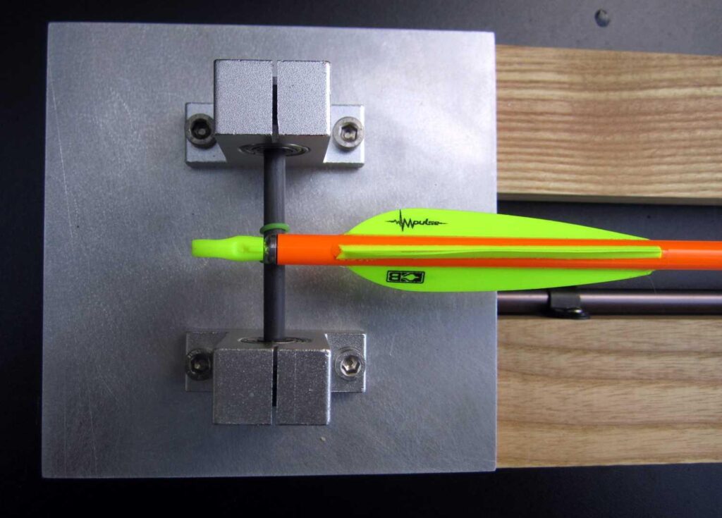
The simplest and most common way to determine an arrow’s spine rating is to place the arrow on two supports — one near the head and one near the fletching. You then hang a weight from the middle of the shaft and measure how much it bends. More sophisticated mechanical testers include a dial, similar to what you’d see on a torque wrench. This electronic tester follows the same principles, but provides digital precision.
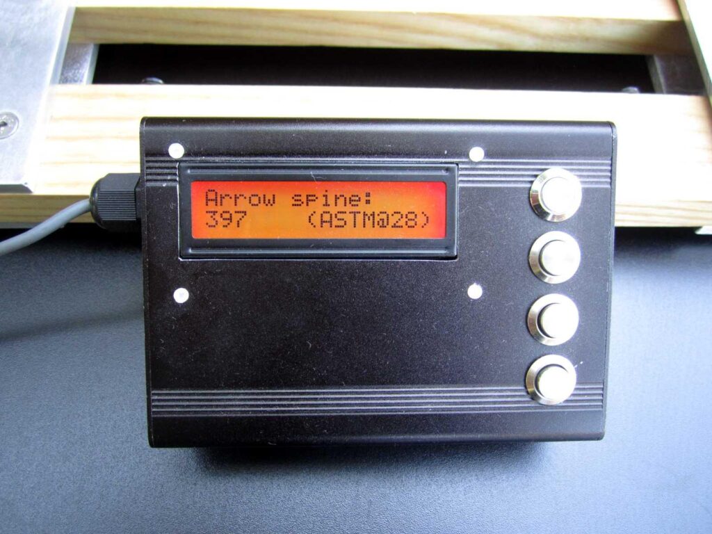
This tester has three load cells. Two are underneath the supports that the arrows rest on. The third is below the center of the shaft. An Arduino Nano board reads the output from the load cells via HX711 amplifier modules. The archer pushes down on the shaft, which pushes onto the middle load cell. Between the three load cells, the Arduino then knows the total force applied to the arrow and the force from the deflected portion of the shaft. A few calculations later and the Arduino outputs the spine rating on a small LCD screen.
It’s a quick and easy way to make sure every arrow in the quiver has the same spine rating, ensuring consistency and repeatability.
The Arduino #Include program was first announced as part of the 2021 Arduino Day event. Since then, the team has been refining exactly how #Include will help members of the Arduino community to spread our love of electronics around the world.
One of the pilot programs has just taken delivery of equipment provided through #Include. This marks an exciting milestone for Arduino, its users, and a whole community of brand new Arduino lovers in Accra, Ghana.
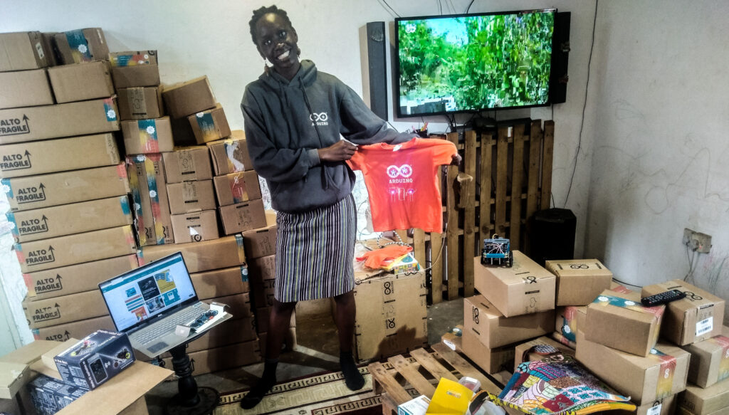
Jenga Labs in Ghana gets #Include gear
Brenda Mboya is well known at Arduino. She was a guest speaker at Maker Faire Rome in 2019. She’s done a huge amount of work in Africa, bringing electronics, robotics and educational technology to students and teachers across Ghana. In 2018, she was listed among the top 25 women in the world to have made a significant contribution to robotics.
Her latest project is Jenga Labs, which she describes as being a “lab on wheels”. The objective is to bring coding and robotics to some of the most remote areas of the region. She’ll be running courses for 7- to 14-year-olds, and Brenda primarily works to encourage young people into robotics. She’s also very active in supporting teachers, and helping them bring, use and understand tech in the classroom.
We’re thrilled that Brenda’s now taken delivery of the Arduino kits and electronic components we sent her as part of the pilot program for #Include.
We can’t wait to see what Brenda’s students create with the tools they now have. It’s exciting on all kinds of levels. Bringing accessible technology to new people and places, for example. Or finding out how we can begin to expand on this early test case for the Arduino #Include initiative.
More about Arduino #Include
The history of Arduino has been one of inclusivity. Everything here is designed to make electronics accessible to as many people as possible. That’s an ongoing challenge that we both relish, and take seriously.
In an effort to bring that philosophy to the forefront of the ongoing business, we’ve developed the Arduino #Include program. We’ll build on our efforts of expanding the understanding of electronics and technology. This will have a strong focus on the diversity values that Arduino also holds dear.
This means making a special effort to bring visibility to people who use Arduino as a tool for inclusivity, equality, social justice and accessibility. We see this very much as an opportunity. It’s a long term program that we hope will help to create positive role models across the tech communities.
Ultimately the #Include initiative will see Arduino help to establish “ambassadors”. It’ll donate hardware and software services, and give visibility to diverse people and groups across the spectrum.
Which brings us to wishing Brenda all the best with her Jenga Labs robotics project as part of the Arduino #Include program.
We’ll keep you posted on Jenga Labs, and about how you can get involved in #Include as the program expands.
This is an edited version of a longer piece first published on Wevolver.
In recent years, industrial enterprises are accelerating their digital transformation and preparing themselves for the fourth industrial revolution (Industry 4.0). This digitization of production processes enables industrial organizations to implement agile and responsive manufacturing workflows, which rely on flexible Information Technology (IT) systems rather than on conventional Operational Technology (OT). This flexibility facilitates a shift from conventional Made-to-Stock (MTS) manufacturing to novel customizable production models like Made-to-Order (MTO), Configure-to-Order (CTO) and Engineering to Order (ETO).
The implementation of Industry 4.0 compliant production systems hinges on the deployment of Cyber-Physical Systems (CPS) in the manufacturing shop floor. In essence, CPS systems comprise one or several internet-connected devices integrated with other production systems in industrial environments. This is the main reason why Industry 4.0 is also referred to as Industrial Internet of Things (IIoT). IIoT includes the subset of IoT (Internet of Things) systems and applications that are deployed in industrial environments such as the manufacturing, energy, agriculture, and automotive sectors. According to recent market studies, the lion’s share of IoT’s market value will stem from IIoT applications rather than from consumer segments.
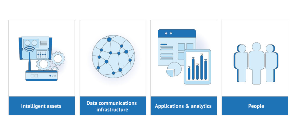
The typical structure of IIoT applications is specified in standards-based architectures for industrial systems such as the Reference Architecture of the Industrial Internet Consortium. It comprises a stack of components that includes sensors and IoT devices, IoT middleware platforms, IoT gateways, edge/cloud infrastructures, and analytics applications.
The Power of Embedded Sensors in the Manufacturing Value Chain
IT systems, enterprise applications (e.g., ERP and Manufacturing Execution System (MES)), and industrial networks for production automation have been around for decades. The real game-changer in Industry 4.0 is the expanded use of embedded sensors in the value chain. Embedded sensors transform manufacturing assets into cyber-physical systems and enable many optimizations that were hardly possible a few years ago. Overall, embedded sensors and other IIoT technologies empower increased efficiencies by transforming raw digital data to factory floor insights and automation actions.
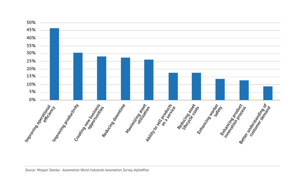
Some of the perceived benefits of IIoT and embedded sensors deployments in production operation include:
Flexible Production Lines
Predictive Maintenance
Quality Management
Supply Chain Management
Zero Defects Manufacturing
Digital Twins
Data analysis options: Edge, Cloud, or combination?
Most IIoT applications include data analytics functionalities such as sensor data analysis based on machine learning techniques. Therefore, they typically collect and process information within cloud computing infrastructures. The latter facilitates access to the required data storage and computing resources. Nevertheless, IIoT deployments in the cloud fall short when it comes to addressing low latency use cases, such as applications involving real-time actuation and control. In such cases, there is a need to execute operations close to the field (i.e., the shopfloor) that cannot tolerate delays for transferring and processing data in the cloud.
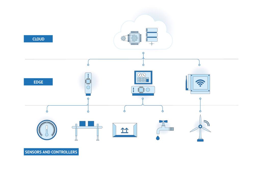
To address real-time, low-latency applications, industrial organizations are deploying IIoT applications based on the edge computing paradigm. The latter involves data collection and processing close to the field, within infrastructures like edge clusters (i.e., local cloud infrastructures), IoT gateways, and edge devices. A recent report by Gartner predicts that by 2023 over 50% of enterprise data will be processed at the edge.
Edge computing deployments are best suited for real-time control applications while helping to economize on bandwidth and storage resources. Specifically, data processing within edge devices facilitates the filtering of IoT data streams and enables enterprises to selectively transmit to the cloud “data points of interest” only. Furthermore, edge computing provides better data protection than cloud computing, as data remains within local edge devices rather than being transmitted to cloud data centers outside the manufacturing enterprise. Moreover, edge analytics functions like AI algorithms on edge devices are much more power-efficient than cloud-based analytics.
In practice, industrial enterprises employ both cloud computing and edge computing for their IIoT use cases. Specifically, they tend to deploy real-time functions at the edge and data-savvy industrial automation functions on the cloud. There is always an interplay between cloud and edge functions towards achieving the best balance between analytics accuracy, computational efficiency, and optimal use of bandwidth and storage resources. Thus, IIoT applications are usually deployed in the scope of a cloud-edge environment.
Nowadays, there are many ways to implement edge computing and its interactions with cloud infrastructures. Likewise, there are also many options for employing machine learning at the edge of an industrial network, such as federated machine learning techniques or even deployment of machine learning functions in embedded devices. The latter involves a convergence of embedded programming with machine learning, characterized as embedded machine learning or TinyML.
State of the art cloud/edge computing paradigms support varying requirements of IIoT use cases in terms of latency, security, power efficiency, and the number of data points needed for training ML algorithms. Future articles in this series will shed light on the technical architecture and the deployment configurations of some of the above-listed cloud/edge paradigms.
The Scaling of IIoT and the Path towards industry 4.0
Industry 4.0 has been around for over five years, yet we are still quite far from realizing the full potential of embedded sensors and the Industrial IoT. Many enterprises have started their deployment journey by setting up data collection infrastructures and deploying CPS systems and IoT devices on their shop floor. There are also several deployments of operational use cases in areas like asset management, predictive maintenance, and quality control. Nevertheless, many use cases are still in their infancy or limited to pilot deployments in pilot production lines or lab environments. Therefore, there is a need for evolving and scaling up existing deployments to enable industrial enterprises to adopt and fully leverage the fourth industrial revolution.
The scaling up of Industry 4.0 use cases hinges on addressing the following challenges technical and organizational challenges:
Legacy compliance for brownfield deployments.
Alleviating data fragmentation in industrial environments.
Addressing the IoT, BigData, and AI skills gap.
Ensuring access to pilot lines and experimentation infrastructures.
Easing IIoT integration end-to-end i.e., from the embedded device to the manufacturing application
Realizing a cultural shift towards Industry 4.0.
Arduino Pro and Industry 4.0
Driven by these challenges, Arduino has recently created its Arduino Pro solution for Professional Applications. It is an all-in-one IoT platform, which combines:
Hardware boards for industrial control, robots, and edge AI applications.
End-to-End secure connectivity solutions for deploying cloud-based applications.
Advanced development environments that enable low code application development.
Ease of Implementation and significant community support.
Conclusion
This article has introduced the Industrial Internet of Things, including its main use cases and business value potential for industrial enterprises. It has shed light on how embedded sensors, cloud/edge computing, and Artificial Intelligence provide a sound basis for optimizing production operations in directions that can improve production time, quality, and cost, while at the same time boosting employees’ safety and customers’ satisfaction.
Read the full version of this article, including references used here, at Wevovler.com.
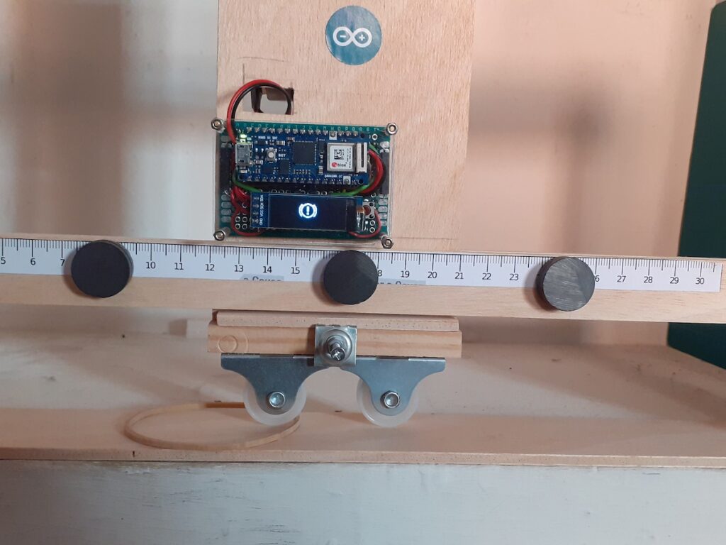
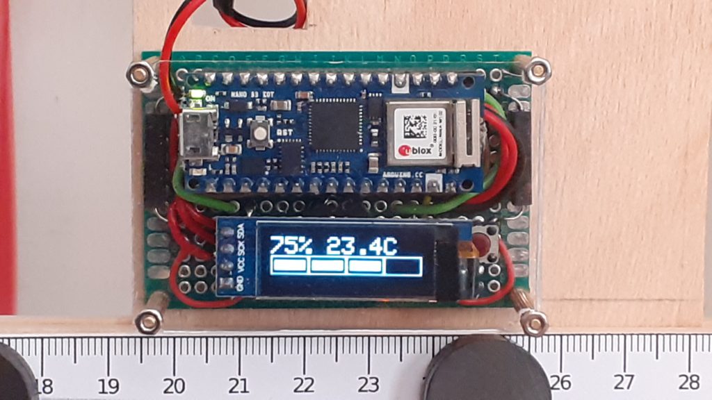
Within an industrial setting, being able to determine if and/or when a machine malfunctions is vital to maintaining safety and uptime. This challenge is what prompted a maker who goes by javagoza on element14 to enter into their Design for a Cause 2021 contest with his device, which he calls the VenTTracker.
At its heart, the VenTTracker uses an Arduino Nano 33 IoT mounted onto a small protoboard that is attached to a sliding surface, such as a window or vent. Under normal operation, the device does nothing, but once an anomaly is detected, including an obstacle or breakdown, the onboard OLED screen shows an alert message.
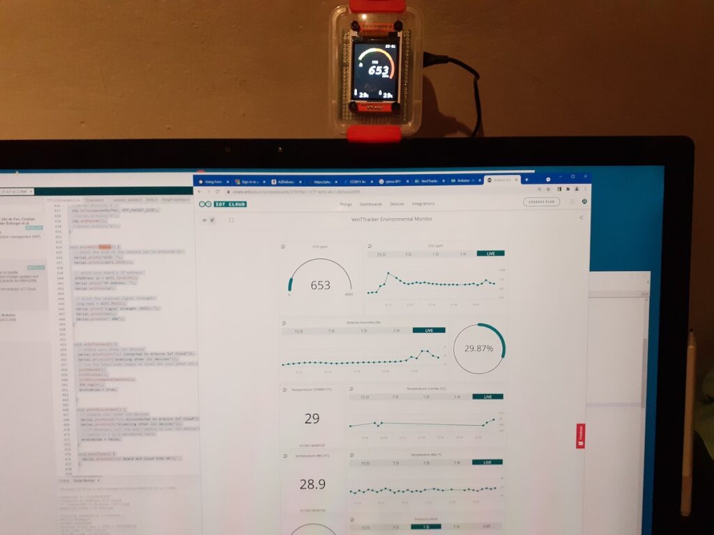
Because this project uses machine learning to differentiate between normal operation and an anomaly, javagoza collected a large dataset of motions from an accelerometer and then uploaded it to Edge Impulse’s Studio. From there, he added a time series processing block and flattening block to generate the features that fed into the Keras neural network for training and validation. Once deployed back to the Arduino, the model performed very well at telling the difference between the window opening normally and something being in the way.
He even included Arduino Cloud functionality to display if the window is open and any anomalies that have been detected so far. There was an additional module constructed for environmental monitoring, which consists of a Nano 33 IoT and a BME680 sensor that sends CO2, temperature, and humidity data to another Cloud dashboard to let users know when to open the window.
Being able to keep oneself accountable while working out is a vital component to almost any good exercise plan, since repetition is the key to success. In response to their significant other wanting a way to track their workouts throughout the week, Instructables user smooth_jamie set out to build a highly interactive device that gives the person using it motivation to continue on after accomplishing the day’s goal.
The project largely consists of a large rectangular enclosure, which houses a series of seven 128×32 OLED screens, along with a single push button next to each one. Just across from the displays is a string of WS2812B LEDs that correspond to that day’s achievement or lack thereof. Jamie had run into the issue of the OLEDs having hardcoded I2C address, so they were forced to use an I2C multiplexer breakout. They also wanted for the device to play a short song to really commemorate meeting that day’s goal, so a speaker and amplifier circuit was added onto the Arduino Mega.
The final step of building this daily run tracker was the code, as it had to handle several different tasks. New targets are entered by holding down a given day’s button and then using the up and down buttons to set it. When the actual distance is entered, the string of RGB LEDs will begin to flash and a tune plays if the goal is met, and the LED next to it turns either red or green afterwards as a reminder.
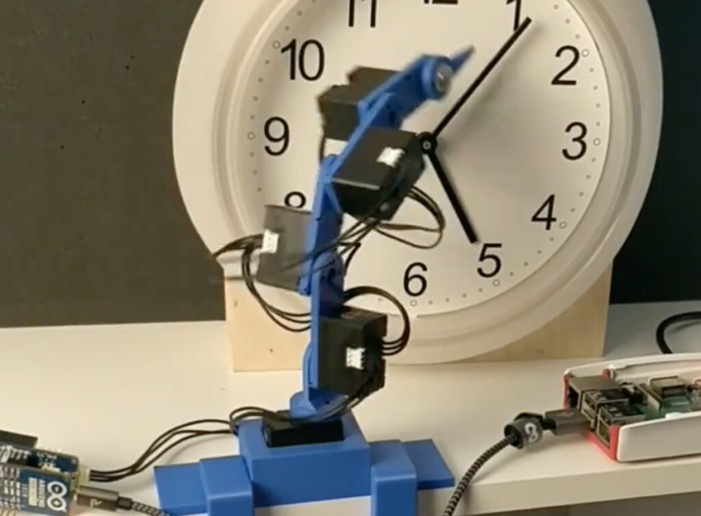
Normally when an inexpensive wall clock stops ticking, you simply buy a new one. However, ‘Developer Hendrik’ decided to bring his broken clock back to life, or some semblance thereof, using a 3D-printed four-axis robot arm dubbed “Serworm Michael.”
Under the control of a MKR 1010 WiFi and DYNAMIXEL MKR Shield, along with a Raspberry Pi, Serworm Michael is set up to push the minute hand into the next position. Five DYNAMIXEL XL330-M288-T servos drive the robot, which are programmed by physically moving the arm and using a command line interface.
You can see it in action in the video below, while more details on Serworm Michael are available on GitHub.
We’re excited to announce that Arduino has partnered with Altium and the IPC Education Foundation (IPCEF) to launch a student electronics design challenge to engage, educate, and enhance PCB design capabilities while developing STEM solutions to environmental challenges.
The Innovation for Environmental Change 2021 International Student Design Competition (#PCBeTheChange) encourages student teams to help address common environmental concerns using Altium’s educational tools with Arduino hardware. Teams from high schools and colleges will be using Altium’s Upverter Modular PCB design software and the Portenta H7 to create a prototype design that will improve the environment in each team’s respective local area. The students will be challenged to tackle one or more environmental concerns, such as air pollution, water quality and solar energy capture.
“At Arduino, we believe that it is very crucial to empower scientists of the future to address common challenges of our time using technology. We’re delighted to partner with Altium LLC and the IPC Education Foundation in the Innovation for Environmental Change 2021 International Student Design Competition; this competition really aligns with our goal of creating the next generation of STEM solutions.” — Lotte Nørregaard Andersen, Head of Arduino Education
Participating teams can enter the design challenge while harnessing Altium’s Upverter Education training modules plus the Upverter Modular tool. Altium features multiple educational initiatives designed to support high school STEM teachers and students, along with programs to support college students and industry professionals.
Teams will be eligible to win cash prizes for each category: high school and college: $1,500 (1st place), $750 (2nd place) and $500 (3rd place), free access to IPC APEX EXPO in San Diego, California from January 25th-27th, 2022 as well as virtual access to AltiumLive 2022 CONNECT, co-located alongside the IPC APEX EXPO at the San Diego Convention Center. Designs will be featured on display at the IPC Design Booth; awards will be presented at the IPC APEX EXPO STEM Outreach Event.
Registration for #PCBeTheChange is now open and runs through Friday, October 1st. Team designs must be received online by Friday, November 19th. Competition winners will be announced on Friday, December 17th, followed by virtual presentations for the first place and runner-up entrants.
Use an Arduino touchscreen to draw the waveforms that you’d like your synth to produce
Arduino Team — August 16th, 2021
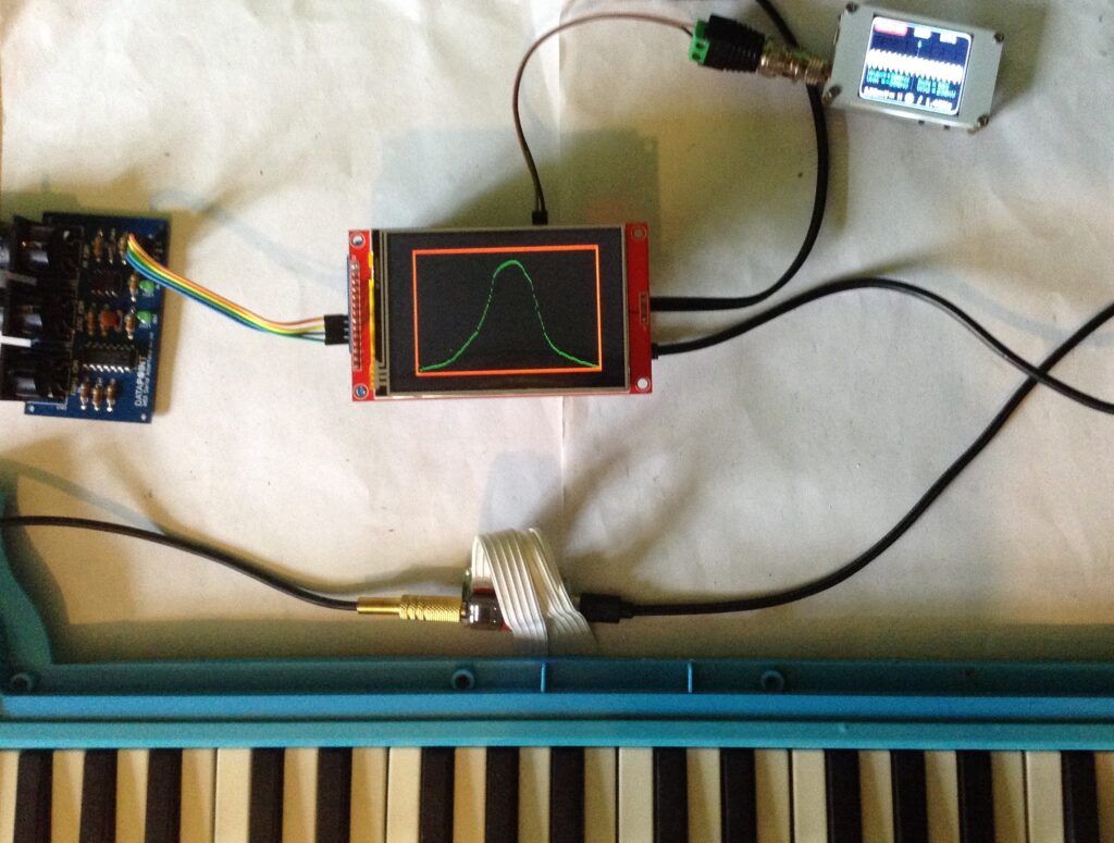
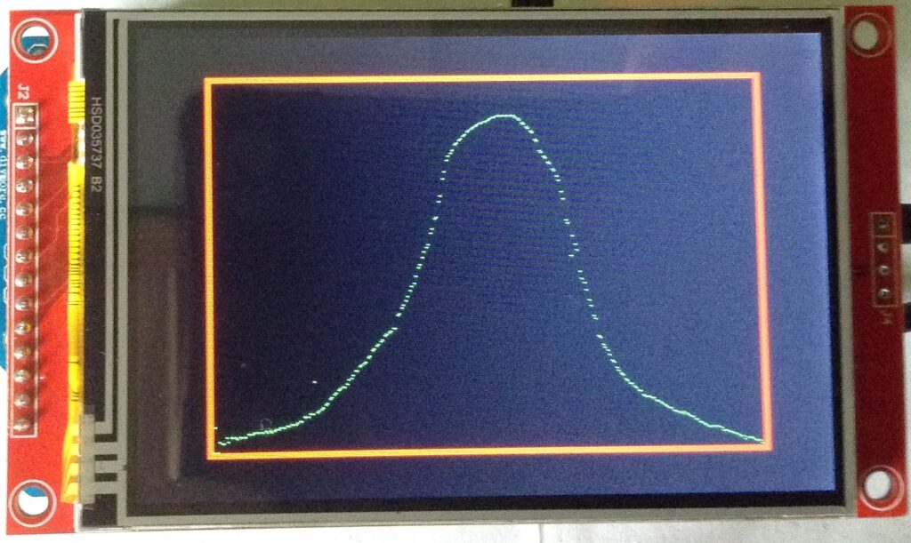
Ordinarily, producing complex waveforms on microcontrollers requires precise adjustments within code in order to work, and this can become quite tedious. Additionally, having to wire up physical inputs such as potentiometers for quick tuning adds a lot of sprawl to a project. This is partially what inspired Kevin, who runs the DIY Electromusic website, to construct a small, Arduino-based device that allows users to sketch the waveform they want outputted via PWM.
The main components of this project are the ILI9488 TFT shield that fits onto an Arduino Uno, along with an amplifier/speaker and an optional output filtering circuit to clean up the audio. Kevin’s unit takes in a MIDI note on the Uno’s RX pin and passes it through a wavetable function that applies the currently displayed waveform on the screen to the note being requested.
Kevin also made a slight modification to the previously mentioned project by replacing the wavetable with a series of five sliders that correspond to various parameters for a MIDI granular synthesizer. His analog version had five large potentiometers that plugged into the analog input pins on an Uno, but this newer version greatly cleaned things up and gives more room for experimentation.
To read more about these innovative audio control projects, you can view them on Kevin’s website here and see a quick demo below.
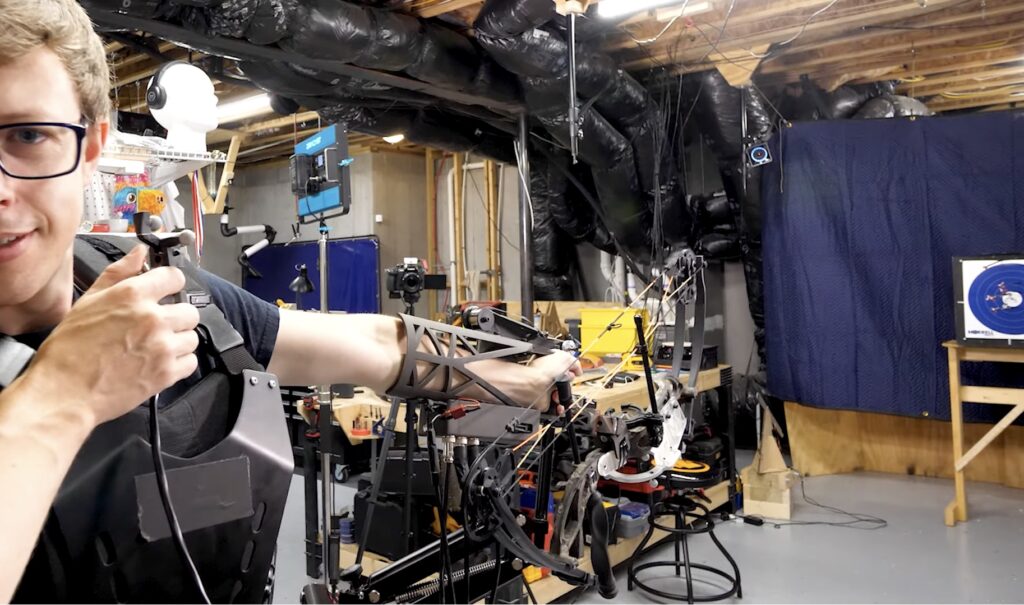
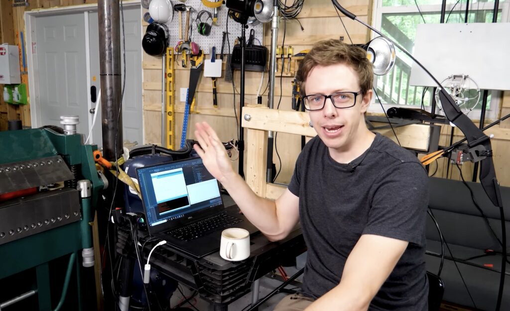
After becoming frustrated at his lack of archery skills and not wanting to spend an eternity practicing getting better, Shane Wighton (known as Stuff Made Here on YouTube) sought to build a rig that could automatically correct his aim for the perfect shot every time. The device is comprised of a rigid sleeve that fits over the wearer’s forearm, along with a pair of stepper motors that can adjust where the bow is pointing either vertically or horizontally via a rack-and-pinion. These motors are driven by an Adafruit microcontroller running CircuitPython and a couple of motor driver modules that provide the necessary current. But that’s not all, he also created a small rig that uses an Arduino Uno and servo motor to autonomously fling targets into the air.
Target tracking is achieved by having a set of eight OptiTrack cameras around the room monitor the space for tiny gray spheres, and through the use of a special triangulation algorithm, they can accurately determine where both the arrow is pointing and where the target is in 3D space. Initially, the system missed all of its shots due to poor software and the wrong kind of bow, so Wighton completely rewrote his program and switched to a compound bow instead.
Once everything had been corrected, the software was able to predict where a flying target would end up according to its speed, and thus had the ability to intercept it. The Auto-Aiming Bow could also hit a target the size of a 3mm-wide circle with scary precision.
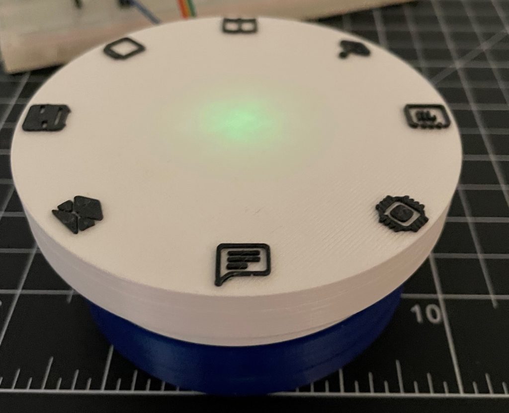
The recent explosion of the number of people working from home has led to some interesting problems, one of these being that getting distracted from your current task is easier than ever. To combat this issue, Hackaday.io member quincy came up with an innovative solution that utilizes a small light-up disk to track what kind of work is being done and for how long, thus keeping the user accountable.
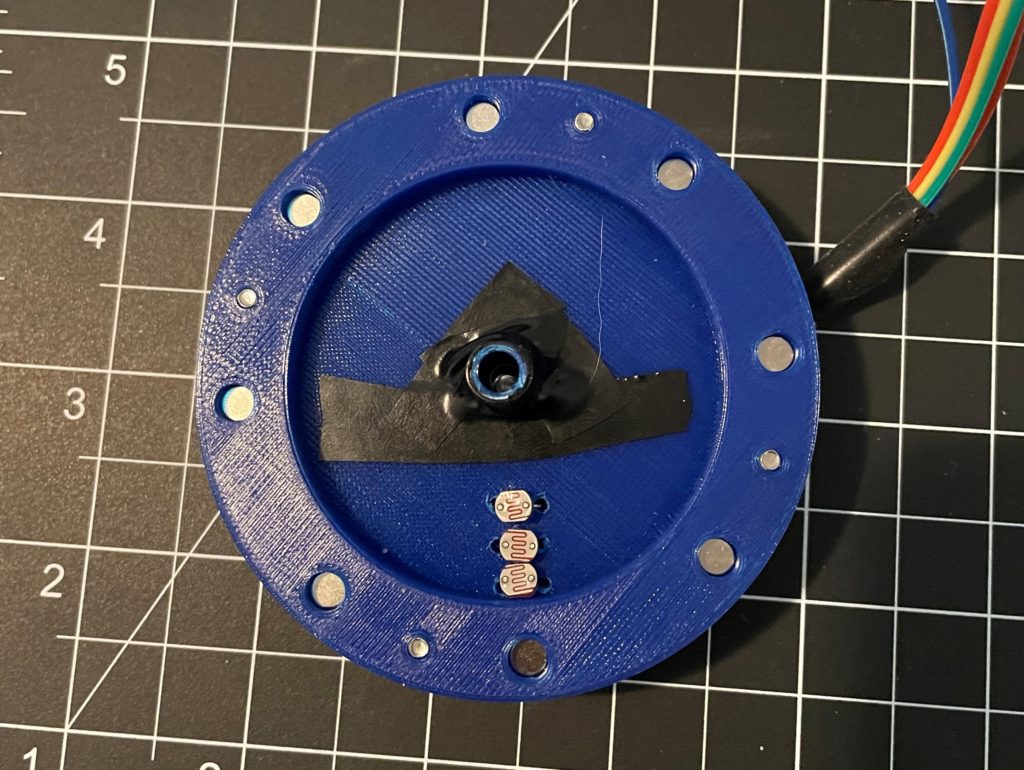
Rather than creating a boring task-tracking cube or a simple timer, Quincy wanted something a bit more, in his words, “magical,” so of course this device would integrate magnets and blinking lights to achieve this goal. It consists of an upper disk with a central bearing that allows it to rotate freely between one of eight different options. The base meanwhile contains a central green LED and a set of three photoresistors. These components are combined in such a way that the channels within the underside of the upper disk form a sort of binary code for each task, so a position can be uniquely identified by seeing which photoresistors are currently active. There is a magnet under each task’s icon that lets it snap into place easily and prevents it from rotating further.
With the hardware completed, Quincy tested out his new rotary time tracker by having it output which task is currently being performed over serial, and then having a separate program take this data and display it in a nice graphical format. You can read more about this project and see the code/components used here on Hackaday.io.
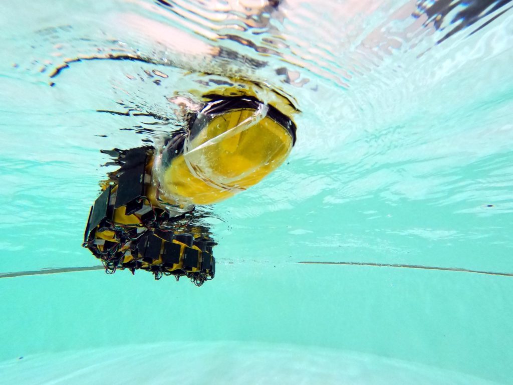
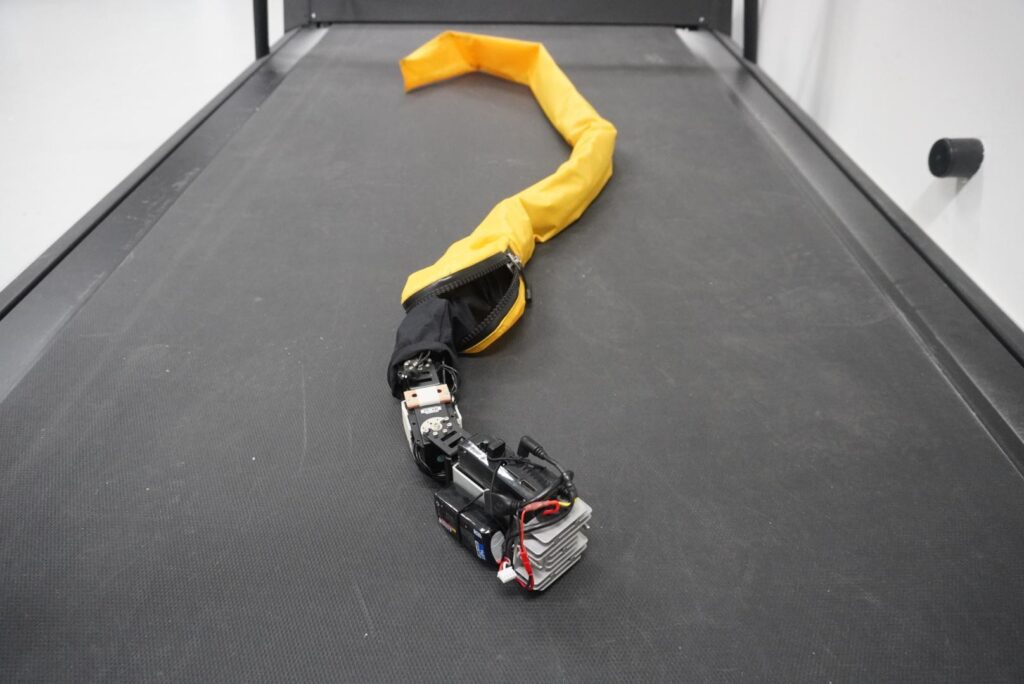
Roboticists often look to nature for inspiration. That makes sense, because animals are very efficient machines, thanks to millions of years of evolution. Even our most sophisticated technology doesn’t come close to matching a common housefly. But we can get closer to mimicking nature at larger scales, as with this robot created by researchers at EPFL that does a great job of swimming like a lamprey.
Lampreys are long, jawless fish that often get mistaken for eels. They swim through the water with a motion similar to a snake slithering across loose sand. To replicate that movement, this robot’s body contains numerous segments joined by servo motors. Each segment also has a force plate on each side. That lets the robot sense the pressure of the water against its body as it swims. An Arduino Mini board monitors the plates through force cells and controls the motors.
This unique setup let the researchers study the ability of some vertebrates to move even with a damaged spinal cord. The “healthy” robot can coordinate the movement of all of its motors. But the robot with the simulated spinal cord injury cannot. The motors past the “injury” can only react to the force plates on their own segments. The team found that the robot was still able to swim efficiently, because the force plates provided enough information to control the motors as needed. This provides valuable information in the field of neuroscience and vertebrate nervous systems.
Over the past few years, Arduino Education has expanded, offering new learning solutions to teachers and students around the world. Today, we have more than 10 kits with exciting online courses for STEM teachers and learners ranging from middle school to university.
When creating these products, we were delighted to collaborate with many brilliant educators, who shared with us their unique teaching styles and provided valuable feedback.
With the pandemic dramatically shaking up the status quo in education, we now have more learning styles than ever. From large schools using hundreds of Arduino kits to smaller classes and study groups. There are even a lot of parents who use kits for homeschooling, along with an increasing numbers of self-learners.
We’re excited to see Arduino Education products being enjoyed in so many different ways, and want to make sure our kits are easy to use and share in every situation. That said, we’re excited to announce several changes to how our educational products are shared.
Personal courses vs. Classroom courses
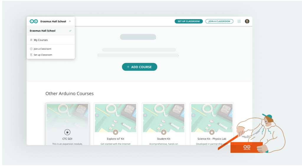
From now on, when you register an Arduino Education kit, the online courses associated with it will be added to your personal collection, accessible via “My Courses” in the profile menu. Courses in your personal collection are only visible to you. This way, if you’re learning by yourself, you have a quick and easy way to access all your learning resources in one place.
If you’re learning together with others, or you’re an educator managing a group of students, you can now set up a classroom. This will create a second collection of products which you can share with other people. You can switch between the different product collections anytime, and transfer products between them.
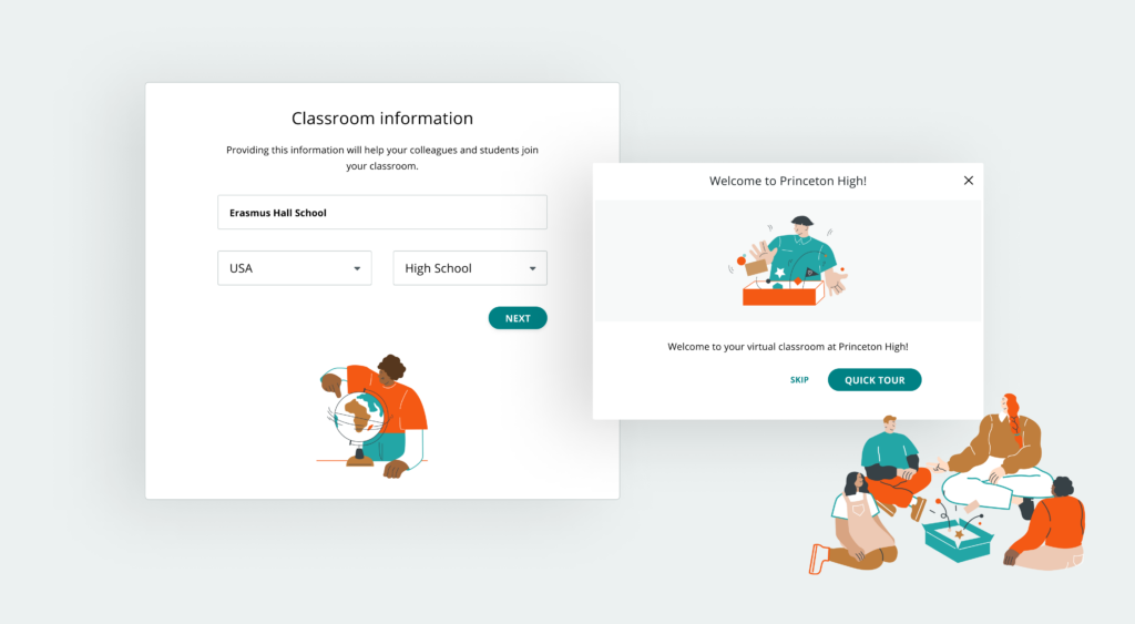
Setting up a classroom
Setting up a classroom takes a matter of minutes. Simply add a few details about yourself and your teaching environment and choose which products you want to share with others.
Once your classroom is set up, you can start inviting students and other educators to join.
Everyone who joins will immediately get access to all online courses that you add to your classroom.
Using the classroom system, you can now share any Arduino Education product with any number of people, and as the classroom admin, you are in full control of who can access your courses, meaning you can add and remove new members anytime.
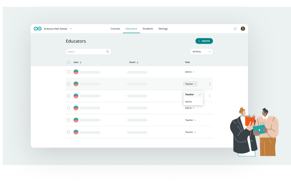
Teacher and admin roles
When you set up a classroom, you become its admin. You have the power to change settings and control the member list and available courses. When you invite your colleagues, you can choose if they should also be an admin, or take the teacher role.
Teachers can add and remove students from the classroom, but cannot manage other educators or change classroom settings. Both admins and teachers will see the educator version of the online content, with educator tips, logbooks and more. Roles can be changed whenever you need, and you can have multiple admins at the same time.
We hope these changes will provide better administration possibilities to institutions with multiple collaborating educators.
Safety for our youngest learners
When working on these updates, we wanted to make sure that the system is usable and safe even for our youngest users. If your students are too young to have an inbox, you can invite them by sharing a classroom code. This way, they can join your classroom without using an email address.
If your students are under the age of 14, you can also be sure they’re in a safe online space. They’ll only encounter child-safe content, and their accounts will be anonymized, with no personal data collected.
We hope these changes will make learning with Arduino Education easier, safer, and more flexible, and we can’t wait to share with you what’s coming next!
Enhance your Arduino development with fast and easy debugging from Segger
Arduino Team — August 12th, 2021
Arduino has partnered with Segger to further support developers in creating their own embedded systems, implementing compatibility of Segger debugging solutions with Portenta boards.
Debuggers are the scalpel that allows a developer to dissect any application code running on embedded hardware. This versatile tool helps the programmer to halt programs at specific points, inspect values stored in memory units, modify CPU registers and enter test data to narrow down on buggy pieces of code. This tool comes in handy when you want to locate malfunctioning code and fix faulty program execution.
J-Link debug probes are the most popular choice for optimizing the debugging and flash programming experience. Among the key benefits are:
Record-breaking flashloaders, up to 3MB/s RAM download speed.
Unlimited Flash Breakpoints feature allows the user to set an unlimited number of breakpoints when debugging in flash memory.
Wide range of CPUs and architectures supported; in fact, everything from single 8051 to mass market Cortex-M to high-end cores like Cortex-A (32- & 64-bit).
Direct interface with SPI flashes, without the need of a CPU between J-Link and the SPI flash.
Supported by major IDEs.
In the meantime, we’re working to make the Arduino IDE 2.0 compatible with Segger debugger solutions.
To quickly get started, check out our new tutorials on the Portenta Breakout and MKR boards. You’ll learn how to debug your Arduino sketch by connecting Portenta Breakout to the Segger J-link device and using the Ozone debugger and performance analyzer.
Ozone is Segger’s full-featured graphical debugger for embedded systems. Thanks to features such as trace, code profiling and code coverage analysis, it’s also an extremely powerful performance analyzer. Ozone supports the debugging of any embedded application on C/C++ source and assembly level. It can load applications built with any toolchain/IDE and even debug the target’s resident application without any source. Ozone includes all well-known debug controls and information windows, while making use of the best performance of J-Link debug probes. The user interface is highly intuitive, yet fully configurable. Each window can be moved, re-sized and docked to fit every developer’s needs.
There are four different J-Link models already available on the Arduino Store:
J-LINK BASE COMPACT: USB powered JTAG debug probe supports a large number of CPU cores. Based on a 32-bit RISC CPU, it can communicate at high speed with supported target CPUs.
J-LINK PLUS COMPACT: With this compact version of the J-Link PLUS, users have an unlimited number of flash breakpoints. Mounts securely and unobtrusively into development and end user equipment
J-LINK EDU: Reserved for educational purposes, the J-LINK EDU offers the same functionalities as the J-Link BASE. It’s been designed to allow students, educational facilities and hobbyists access to top of the line debug probe technology.
J-LINK EDU MINI: The smallest J-Link debugger, intended for non-commercial use.
To connect the Portenta boards with J-Link debuggers, there are two adapters available: Segger’s 50-Mil 10-Pin Patch Adapter and J-Link 19-pin Cortex-M Adapter. The 50-Mil 10-Pin Patch Adapter converts the standard 20 pin 0.1″ connector to the standard 10-pin 0.05″ Cortex-M connector. This allows custom connections/wiring between the 20-pin and 10-pin side.
The 19-Pin Cortex-M Adapter allows JTAG, SWD, and SWO connections between J-Link and Cortex-M based target hardware systems. It adapts from the 20-pin 0.1” JTAG connector to a 19-pin 0.05” Samtec FTSH connector as defined by Arm.
For more information and tech specs, please check out the Segger items in the store.
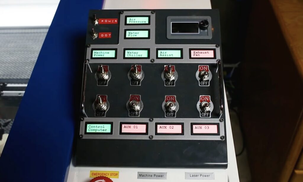
Laser cutters require quite a lot of power and laser tubes need active water cooling, which means you need a coolant reservoir and a water pump. You also need an exhaust fan to remove smoke, which will reduce the laser’s efficacy. Add in a computer, positioning laser, etc., and you’ve got quite a lot to control. That’s why Kaleb Clark used an Arduino to create a control panel for his laser cutter.
This control panel provides several toggles switches, which Clark can flip to turn on the water pump, the air assist, and so on. Each switch has a corresponding WS2812B individually-addressable RGB LED indicator light. There are also status lights that tell him if the air pressure and water flow are in the correct range. Instead of messing around with extension cords and outlets, he can flip all the switches in sequence and then start cutting. When the job finishes, he can flip them all back off.
Those switches mount onto a custom acrylic panel attached to the laser cutter and there is a separate sheet metal enclosure that contains all the relays. In addition to the switches and status lights, the control panel houses the laser cutter’s current meter. An Arduino Mega monitors the toggle switches and activates the relays according their positions. The board also monitors an air pressure sensor and water flow sensor to ensure that they are active, since improper cooling can destroy the expensive laser tube and a lack of air assist can damage parts.
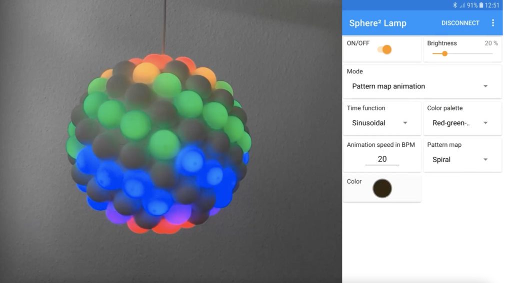
There are already countless projects that utilize individually addressable RGB LED strips in some way or another, except most of them lack a “wow” factor. This is one problem that Philipp Niedermayer’s Sphere2 Lamp does not suffer from, as it is a giant sphere comprised of 122 smaller domes (cut ping pong balls) that are each lit by their own LED. The project uses an Arduino Nano running code with the FastLED library to output signals via its GPIO pins to the LEDs. It is controlled over its serial interface by a Nano 33 BLE Sense since the latter has integrated BLE functionality.
Niedermayer also wrote a dedicated app for starting and stopping animations on the Sphere2 Lamp. The Android application features an interface that lets users control not only the selected color or colors, but the brightness and the speed at which the animation plays as well. Currently, the app has a set of around both ten animations and color palettes each, although this number can certainly be increased in the future.
The Sphere2 Lamp is an extremely unique-looking showcase of what is capable with just a couple of Arduino boards, some LED strips, and innovative programming. You can view the project’s write-up here on Hackster.io and see its code on GitHub.
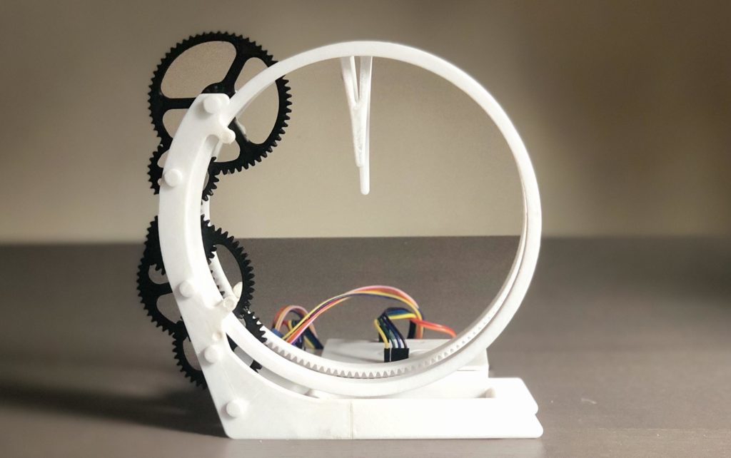
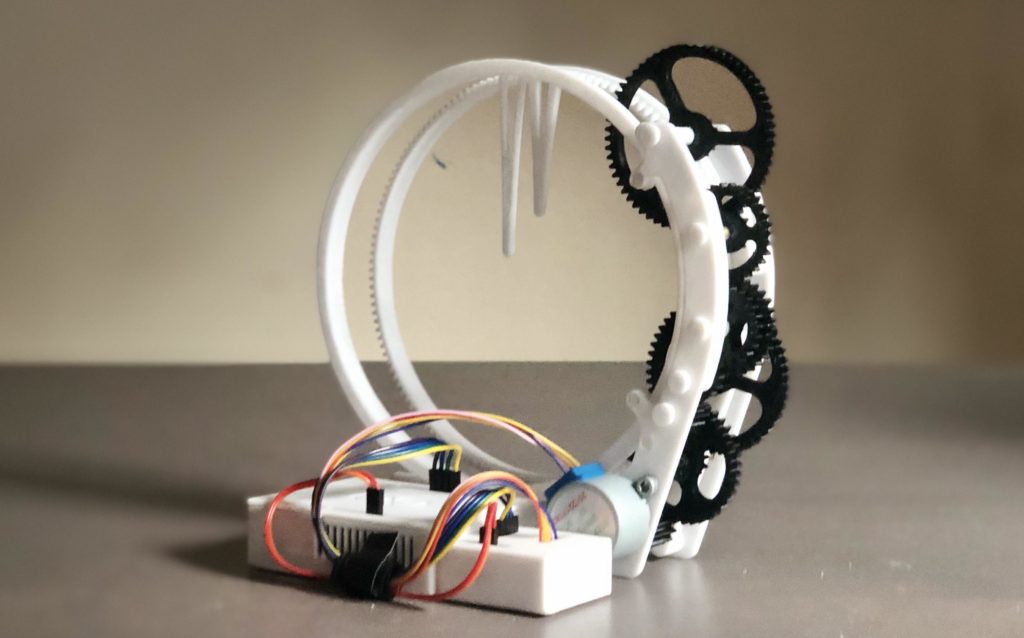
Simply looking at a traditional analog clock sitting on a wall somewhere got pretty boring for one Instructables user who goes by saulemmetquinn, which is partially why they wanted to create a novel design instead. Their device uses almost entirely 3D-printed components that come together to form the “Holo Clock,” since it seems holographic with its floating minute and hour hands.
The Holo Clock project started with a surprisingly complex design in CAD software. There are two rings that are lined with teeth that sit stacked horizontally. The back ring is the minute hand, and because it is moved almost directly by the stepper motor, it spins more quickly. The hour hand is driven by a set of gears that reduce the output of the minute hand’s cogs by a factor of 60, thus making it turn at the correct rate.
The electronics for the clock are extremely simple. It uses an Arduino Uno with a set of four output wires, along with power and ground, to control a ULN2003 stepper motor driver. This in turn outputs current to a generic 5V stepper motor that spins the first drive gear at a known, precise rate for consistent timing. Likewise, the code is also straightforward, as all it must do is step the motor a certain amount depending on how many steps are left within the loop.
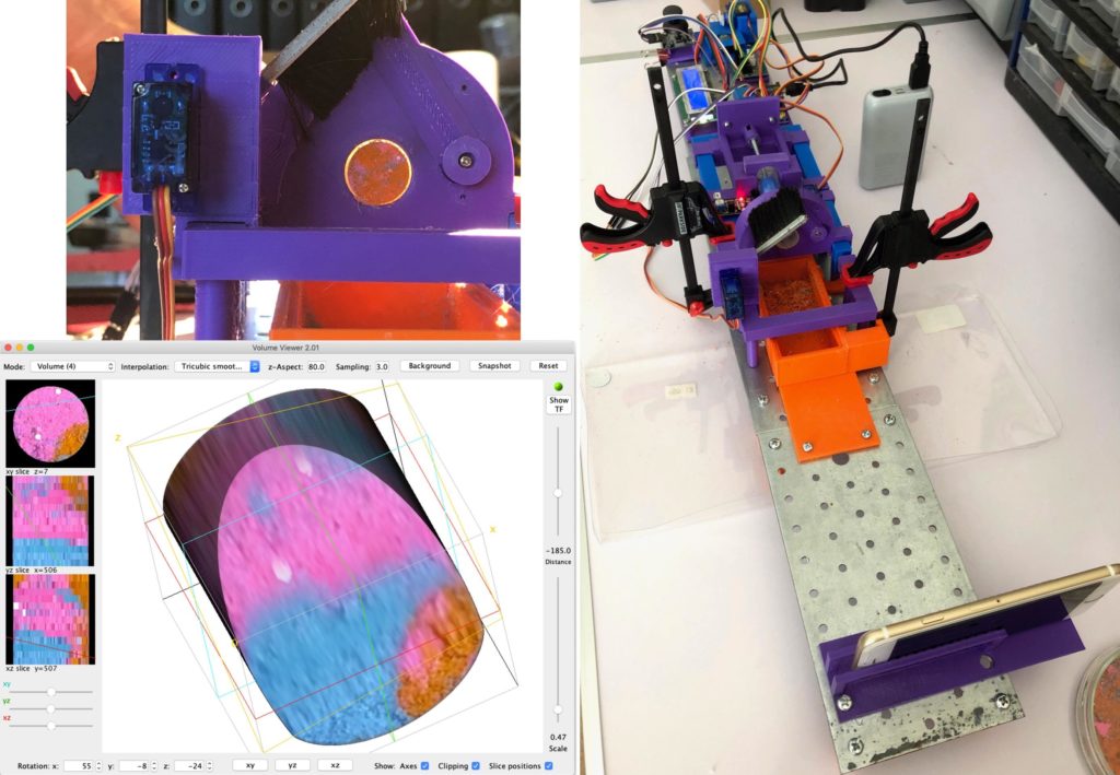
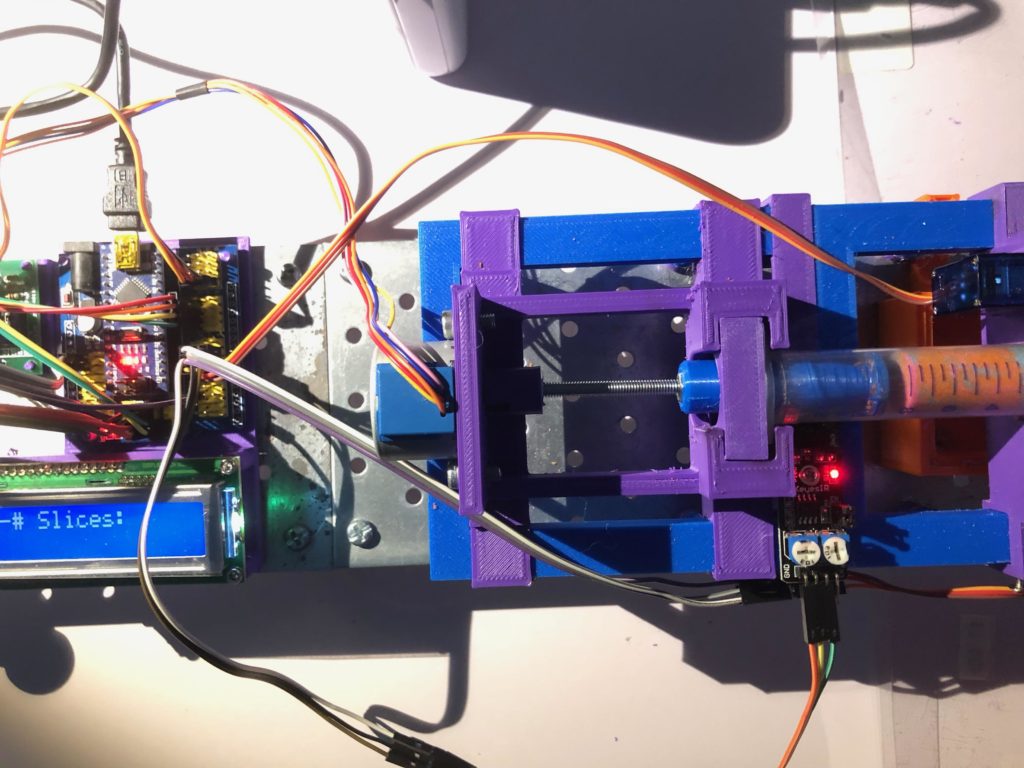
FDM 3D printers work by taking a model, creating many thin slices of it, and then extruding plastic to produce the desired shape. But what happens if you want to reverse that process, e.g. take many tiny slices of something and build a model digitally? This is commonly done with medical imaging device such as MRI machines, but Danilo Roccatano wanted to design a much smaller and cheaper version that works with sand.
His device, which he calls the Magic Sand Slicer, works just as the name implies. Core samples of wet, colored sand are taken from a larger vessel and then placed into an extruder. Next, a 5V stepper motor rotates a long screw that pushes the plunger of the syringe, thus causing sand to extrude at a constant rate. A brush then cleans the surface to make it smooth and a smartphone camera takes a picture. A single Arduino Nano manages everything from the motors to the IR limit switch.
With all the pictures taken, each one is cropped to just its cross-sectional area and then passed to a program called ImageJ which uses those 2D images to create a 3D model. This colorful model can be zoomed, rotated, panned, and sliced virtually, allowing the user to see every intricate detail within their sample. Eventually, Roccatano wants to expand this functionality to other mediums such as rocks and insect-made tunnels.
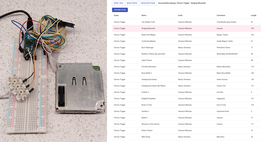
Listening to those classic 16-bit sounds from the ’90s video game era brings back a wave of nostalgia for those who grew up with a console. On the Super Nintendo Entertainment System, outputting sound was accomplished by an integrated circuit called the SNES Audio Processing Unit (APU for short), which was responsible for taking SNES SPC files and transforming them into waveforms. Mauri Mustonen — who goes by Kazooie on YouTube — wanted to isolate this chip to play authentic music from his favorite tracks on his browser without needing to boot up the entire SNES console.
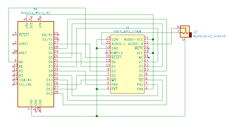
The system he came up with has an Arduino Micro at its heart that is connected to the SNES APU via series of wires. Some of these links are for putting the APU into read or write mode, while others set the desired port and address for where the song data should be written. Data is sent or received over a set of eight parallel data lines.
There is a web-based frontend written in Python that allows a user to select their songs of choice, which are transferred to the Arduino over USB and then sent to the APU via its parallel lines. From there, the IC runs a bootloader that begins playing the audio files.
You can read more about how this system works and check out the code here on GitHub, or you can see Mustonen’s demo video below.
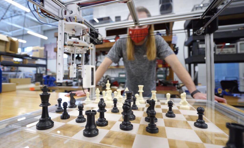
Almost done with his degree in mechanical engineering, Rose-Hulman Institute of Technology student Josh Eckels had the inspiration to put what he learned to the test by creating an AI-powered robot that plays chess against a human opponent. The system is essentially a giant cube fashioned from a series of aluminum extrusions placed at right angles with a large chess board at its base. At the top is a gantry made with a few metal rods and timing belts that slide the X axis and grabbing mechanism to the correct positions.
Four total stepper motors were used to move the grabber, including one for the X axis, another for the Y axis, a motor that spins a threaded rod to lift the gripper, and a final motor that rotates to open or close it. All of these motors connect to a central Arduino that has a CNC shield on top. This is connected via a USB cable to a Raspberry Pi running the Stockfish chess engine.
Stockfish is a great chess engine that keeps track of the current state of the game and makes moves according to the selected skill level. At the upper ranges, it becomes nearly, if not fully, impossible to beat by a human. The player selects on a screen where they want to position their piece, which then causes the robot to pick it up and place it somewhere else. Afterwards, the engine makes its move.
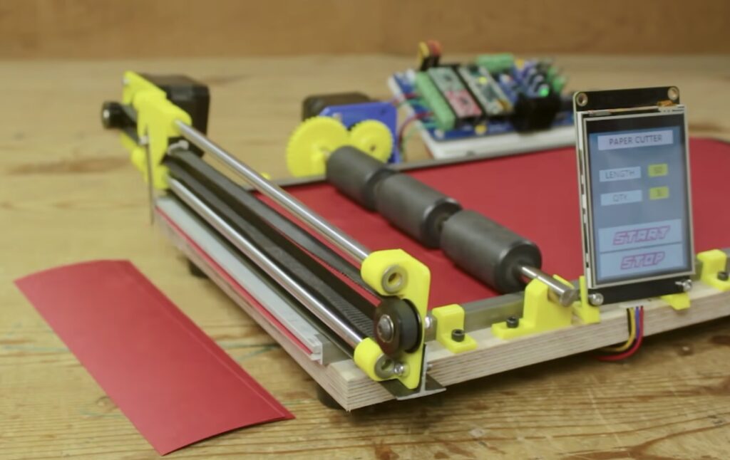
Sometimes, art projects can require the creation of many different pieces of material to be used in the construction of an item. Imagine wanting to build a mosaic out of construction paper but then realizing you’ll need hundreds of tiny strips that are each cut to the exact same length. Luckily, YouTuber Mr Innovative has come up with a solution in the form of an Arduino-based paper cutter. This project follows from a recent one where he assembled an automatic wire cutting machine that can handle up to four different colors simultaneously.
Mr Innovative’s design consists of a large block of wood for the base with a pair of opposing, parallel rails on either side. Just beside one of these is a NEMA 17 stepper motor with a gear that meshes with and rotates a set of rubber rollers that span the entire width of the machine to feed paper through. At the end of the base is another rail that supports the cutting head (a razor blade) which is slid back and forth with another stepper motor.
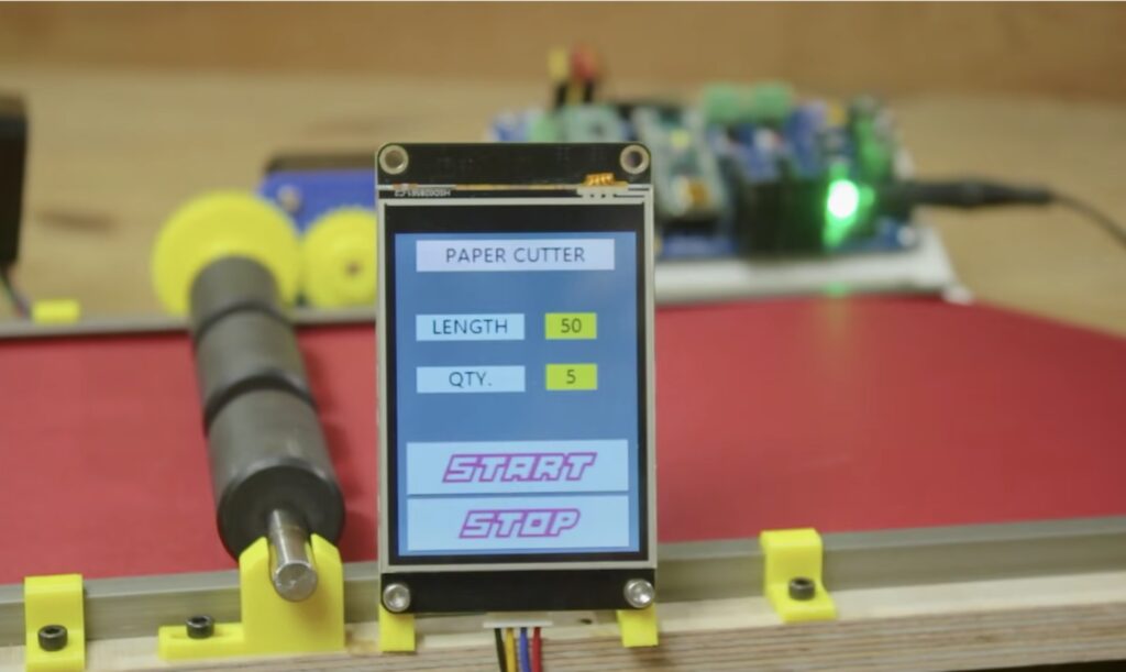
Both motors are driven by a custom control board that houses a pair of A4988 motor drivers and an Arduino Nano. An I2C-enabled screen sits at the front, and it displays a simple GUI with which the user can select both the length of each paper strip and how many should be cut.
You can view this project in more detail in Mr Innovative’s demo/build video below.
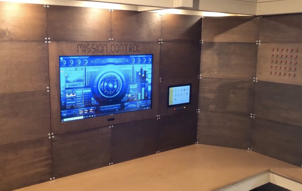
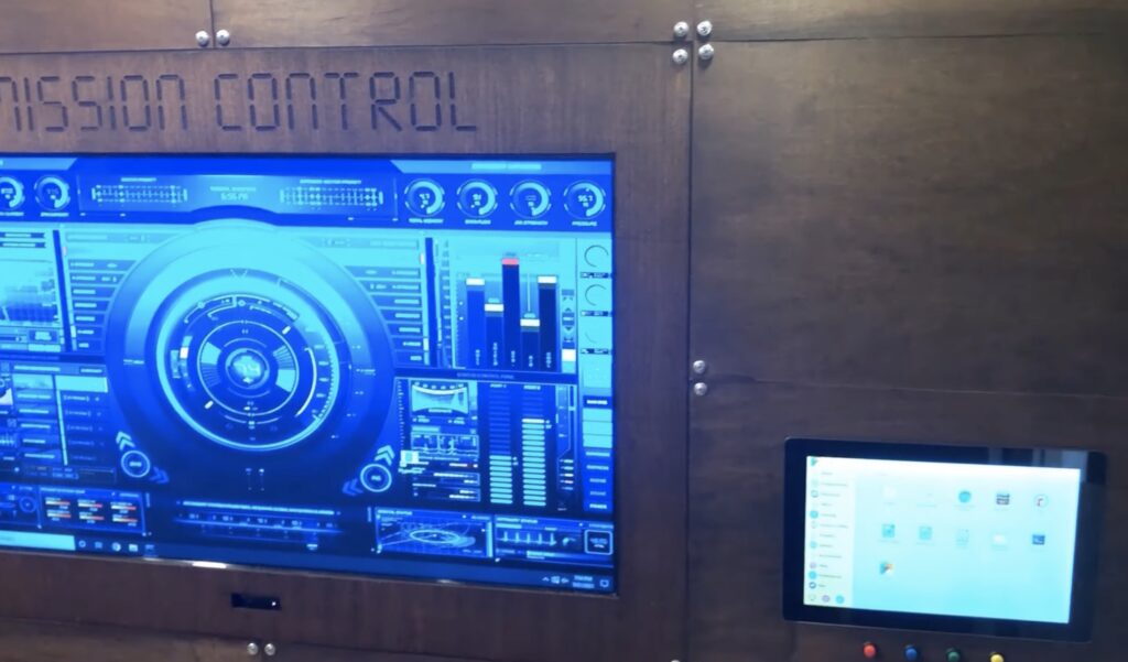
Almost every maker has run into the problem of not being able to find a convenient display or power source for their project prototype, and thus leading to minor delays and some frustration. However, YouTuber Another Maker has come up with an open source desk concept that makes finding these things simple. The system he built uses a large grid of swappable panels that can simply slide into place within a wooden frame. Behind these are a few devices for both power and connectivity, such as power strips, an Ethernet switch (with PoE capabilities), and an HDMI switch for changing between a Raspberry Pi and a PC.
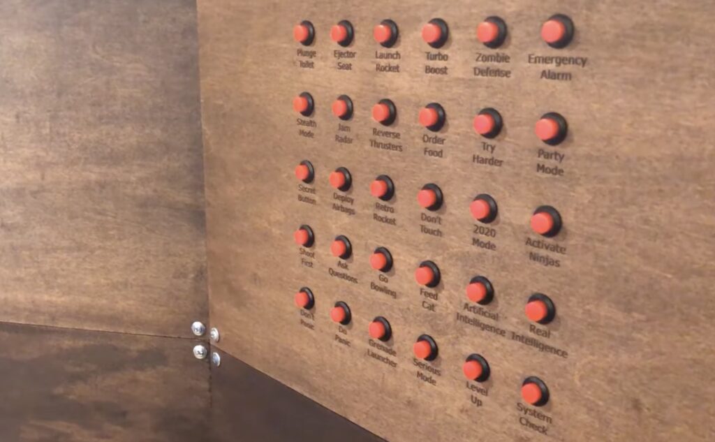
So far, only a single specialized panel has been constructed, although Another Maker has plans for more of them. This current iteration features an array of 30 momentary pushbuttons that all feed into an Arduino Mega. When one of these labeled buttons are pressed, a command is sent via the Ethernet shield to an adjacent home server, where it can control an RGB light strip or interact with an MQTT client.
To the right of the large, central television is a smaller touchscreen that has a Raspberry Pi just behind itself. For now, it doesn’t do all that much, but it can certainly change if/when a new project comes along. You can learn more about Another Maker’s open source desk system in the video below.
Um dir ein optimales Erlebnis zu bieten, verwenden wir Technologien wie Cookies, um Geräteinformationen zu speichern und/oder darauf zuzugreifen. Wenn du diesen Technologien zustimmst, können wir Daten wie das Surfverhalten oder eindeutige IDs auf dieser Website verarbeiten. Wenn du deine Einwillligung nicht erteilst oder zurückziehst, können bestimmte Merkmale und Funktionen beeinträchtigt werden.
Funktional
Immer aktiv
Die technische Speicherung oder der Zugang ist unbedingt erforderlich für den rechtmäßigen Zweck, die Nutzung eines bestimmten Dienstes zu ermöglichen, der vom Teilnehmer oder Nutzer ausdrücklich gewünscht wird, oder für den alleinigen Zweck, die Übertragung einer Nachricht über ein elektronisches Kommunikationsnetz durchzuführen.
Vorlieben
Die technische Speicherung oder der Zugriff ist für den rechtmäßigen Zweck der Speicherung von Präferenzen erforderlich, die nicht vom Abonnenten oder Benutzer angefordert wurden.
Statistiken
Die technische Speicherung oder der Zugriff, der ausschließlich zu statistischen Zwecken erfolgt.Die technische Speicherung oder der Zugriff, der ausschließlich zu anonymen statistischen Zwecken verwendet wird. Ohne eine Vorladung, die freiwillige Zustimmung deines Internetdienstanbieters oder zusätzliche Aufzeichnungen von Dritten können die zu diesem Zweck gespeicherten oder abgerufenen Informationen allein in der Regel nicht dazu verwendet werden, dich zu identifizieren.
Marketing
Die technische Speicherung oder der Zugriff ist erforderlich, um Nutzerprofile zu erstellen, um Werbung zu versenden oder um den Nutzer auf einer Website oder über mehrere Websites hinweg zu ähnlichen Marketingzwecken zu verfolgen.