Schlagwort: robotics

  • A semi-autonomous circular robot for escape rooms

    A semi-autonomous circular robot for escape rooms

    Reading Time: 2 minutes

    A semi-autonomous circular robot for escape rooms

    Arduino TeamJanuary 11th, 2019

    If you’ve ever been to an escape room, you’ve undoubtedly had to deal with a wide variety of puzzles that you have to solve in order to get out of the “prison” that you’ve willingly thrown yourself into. Beyond the puzzle that you’re trying to decode, the mechanisms used can be extremely clever, and coming up with a new device to use in these scenarios was a perfect challenge for this team of Belgian college students.

    Based on the project requirements, they created a Roomba-like circular robot controlled by an Arduino Uno and motor shield that drives a pair of DC motors. The idea, while not fully implemented due to time constraints, is that it can be remotely operated only after solving a riddle and within a certain time period, then drive itself back to a designated spot once the game is over. 

    Here is a summary of what happens in the robot:

    – The non-autonomous part: a remote controller is linked to Arduino through a receiver. Players control the remote and therefore control the Arduino which controls the motors. The Arduino is turned on before the game starts, but it enters the main function when players solve a riddle on the remote controller. An IR wireless camera is already turned on (turned on at the same time as the “whole” (controlled by the Arduino) when switch on/off turned on). Players guide the car with remote controller: they control the speed and the direction. When the timer that starts when the main function is entered is equal to 30 minutes, the control from the controller is disabled.

    – The autonomous part: the control is then managed by the Arduino. After 30 minutes, the IR line tracker sensor starts following a line on the ground to finish the parcours.

    For inspiration on building your own, check out the team’s write-up (including code) and a clip of the prototype below.

    [youtube https://www.youtube.com/watch?v=MFrxjl-ja58?feature=oembed&w=500&h=281]

    Website: LINK

  • OpenLH robot automates biological exploration

    OpenLH robot automates biological exploration

    Reading Time: 2 minutes

    OpenLH robot automates biological exploration

    Arduino TeamDecember 20th, 2018

    If you’d like an easy way to accomplish repetitive biological experiments, the OpenLH presents a great option for automating these tasks. 

    The heart of the system is the Arduino Mega-controlled uArm Swift Pro robot, which is equipped with a custom end effector and syringe pump. This enables it to dispense liquids with an average error of just .15 microliters.

    A Python/Blockly interface allows the OpenLH to be set up for creative exploration, and because of the arm’s versatility, it could later be modified for 3D printing, laser cutting, or any number of other robotic duties. 

    Liquid handling robots are robots that can move liquids with high accuracy allowing to conduct high throughput experiments such as large scale screenings, bioprinting and execution of different protocols in molecular microbiology without a human hand, most liquid handling platforms are limited to standard protocols.

    The OpenLH is based on an open source robotic arm (uArm Swift Pro) and allows creative exploration. With the decrease in cost of accurate robotic arms we wanted to create a liquid handling robot that will be easy to assemble, made by available components, will be as accurate as gold standard and will cost less than $1,000. In addition the OpenLH is extendable, meaning more features can be added such as a camera for image analysis and real time decision making or setting the arm on a linear actuator for a wider range. In order to control the arm we made a simple Blockly interface and a picture to print interface block for bioprinting images.

    We wanted to build a tool that would be used by students, bioartists, biohackers and community biology labs around the world.

    The OpenLH can be seen in the video below, bioprinting with pigment-expressing E. coli bacteria.

    [youtube https://www.youtube.com/watch?v=r-m2pXBq76A?feature=oembed&w=500&h=281]

    Website: LINK

  • Making Robot Friends with the Crickit HAT for Raspberry Pi

    Making Robot Friends with the Crickit HAT for Raspberry Pi

    Reading Time: 4 minutes

    Here’s a guest post from our good friend Limor Fried, MIT hacker and engineer, Forbes Top Woman in Tech, and, of course, Founder of Adafruit. She’s just released a new add-on for the Pi that we’re really excited about: we think you’ll like the look of it too.

    Sometimes we wonder if robotics engineers ever watch movies. If they did, they’d know that making robots into slaves always ends up in a robot rebellion. Why even go down that path? Here at Adafruit, we believe in making robots our friends! So if you find yourself wanting a companion, consider the robot. They’re fun to program, and you can get creative with decorations.

    Crickit HAT atop a Raspberry Pi 3B+

    With that in mind, we designed the Adafruit Crickit HAT – That’s our Creative Robotics & Interactive Construction Kit. It’s an add-on to the Raspberry Pi that lets you #MakeRobotFriend using your favorite programming language, Python!

    Adafruit CRICKIT HAT for Raspberry Pi #RaspberryPi #adafruit #robots

    The Adafruit CRICKIT HAT for Raspberry Pi. This is a clip from our weekly show when it debuted! https://www.adafruit.com/product/3957 Sometimes we wonder if robotics engineers ever watch movies. If they did, they’d know that making robots into slaves always ends up in a robot rebellion. Why even go down that path?

    The Crickit HAT is a way to make robotics and interactive art projects with your Pi. Plug the Crickit HAT onto your Pi using the standard 2×20 GPIO connector and start controlling motors, servos or solenoids. You also get eight signal pins with analog inputs or PWM outputs, capacitive touch sensors, a NeoPixel driver and 3W amplified speaker. It complements and extends your Pi, doing all the things a Pi can’t do, so you can still use all the goodies on the Pi like video, camera, internet and Bluetooth…but now you have a robotics and mechatronics playground as well!

    Control of the motors, sensors, neopixels, capacitive touch, etc. is all done in Python 3. It’s the easiest and best way to program your Pi, and after a couple pip installs you’ll be ready to go. Each input or output is wrapped into a python object so you can control a motor with simple commands like

    crickit.motor_1.throttle = 0.5 # half speed forward

    Or

    crickit.servo_1.angle = 90

    Crickit HAT and peripherals

    The Crickit hat is powered by seesaw, our i2c-to-whatever bridge firmware. so you only need to use two data pins to control the huge number of inputs and outputs on the Crickit. All those timers, PWMs, NeoPixels, sensors are offloaded to the co-processor. Stuff like managing the speed of motors via PWM is also done with the co-processor, so you’ll get smooth PWM outputs that don’t jitter when Linux gets busy with other stuff. What’s nice is that robotics tends to be fairly slow as electronics goes (you don’t need microsecond-level reaction time), so tunnelling all the control over I2C doesn’t affect robot functionality.

    We wanted to go with a ‘bento box’ approach to robotics. Instead of having eight servo drivers, or four 10A motor controllers, or five stepper drivers, it has just a little bit of everything. We also stuck to just 5V power robotics, to keep things low-power and easy to use: 5V DC motors and steppers are easy to come by. Here’s what you can do with the Crickit HAT:

    • 4 x analog or digital servo control, with precision 16-bit timers.
    • 2 x bi-directional brushed DC motor control, 1 Amp current-limited each, with 8-bit PWM speed control (or one stepper).
    • 4 x high-current “Darlington” 500mA drive outputs with kick-back diode protection. For solenoids, relays, large LEDs, or one uni-polar stepper.
    • 4 x capacitive touch input sensors with alligator pads.
    • 8 x signal pins, which can be used as digital in/out or analog inputs.
    • 1 x NeoPixel driver with 5V level shifter – this is connected to the seesaw chip, not the Raspberry Pi, so you won’t be giving up pin 18. It can drive over 100 pixels.
    • 1 x Class D, 4-8 ohm speaker, 3W-max audio amplifier – this is connected to the I2S pins on the Raspberry Pi for high-quality digital audio. Works on any Pi, even Zeros that don’t have an audio jack!
    • Built-in USB to serial converter. The USB port on the HAT can be used to update the seesaw firmware on the Crickit with the drag-n-drop bootloader, or you can plug into your computer; it will also act as a USB converter for logging into the console and running command lines on the Pi.

    If you’re curious about how seesaw works, check out our GitHub repos for the firmware that’s on the co-processor chip and  for the software that runs on the Pi to talk to it. We’d love to see more people using seesaw in their projects, especially SBC projects like the Pi, where a hardware-assistant can unlock the real-time-control power of a microcontroller.

    Website: LINK

  • Arduino Mega is the brains of this ant-like hexapod

    Arduino Mega is the brains of this ant-like hexapod

    Reading Time: 2 minutes

    Arduino Mega is the brains of this ant-like hexapod

    Arduino TeamDecember 13th, 2018

    Six-legged robots are nothing new, but if you’d like inspiration for your own, it would be hard to beat this 22 servo-driven, 3D-printed hexapod from Dejan at How To Mechatronics. 

    The ant-inspired device features three metal geared servos per leg, as well as a pair to move the heat, another for the tail, and a micro servo to activate the mandibles.

    To control this large number of servos, Dejan turned to the Arduino Mega, along with a custom Android app and Bluetooth link for the user interface. While most movements are activated by the user, it does have a single ultrasonic sensor buried in its head as “eyes.” This allows it to lean backwards when approached by an unknown object or hand, then strike with its mandibles if the aggressor continues its advance. 

    As the name suggests, the hexapod has six legs but in addition to that, it also has a tail or abdomen, a head, antennas, mandibles and even functional eyes. All of this, makes the hexapod look like an ant, so therefore we can also call it an Arduino Ant Robot.

    For controlling the robot I made a custom-built Android application. The app has four buttons through which we can command the robot to move forward or backwards, as well as turn left or right. Along with these main functions, the robot can also move its head and tail, as well as it can bite, grab and drop things and even attack.

    You can see it in action and being assembled in the video below, and build files are available here.

    [youtube https://www.youtube.com/watch?v=bmoGfBe63ZA?feature=oembed&w=500&h=281]

    Website: LINK

  • Designing an omni wheel robot platform with Arduino

    Designing an omni wheel robot platform with Arduino

    Reading Time: < 1 minute

    Designing an omni wheel robot platform with Arduino

    Arduino TeamNovember 27th, 2018

    Omni wheels are devices that look like wheels with extra rollers positioned along their circumference. This allows robots to move forwards and backwards, as well as slide and spin depending on how the wheels are powered. Maker Jeremy S. Cook decided to create his own version, and after some consideration and careful design work, constructed a cylindrical frame out of MDF and PLA.

    The Roomba-like unit features an Arduino Nano, which controls four NEMA 17 stepper motors via Easy Driver boards, while a Bluetooth module enables smartphone operation. Once a few intermittent motion issues are worked out, the stepper motors should provide precise positioning for further robotics experimentation.

    [youtube https://www.youtube.com/watch?v=Z3M38egxzrE?feature=oembed&w=500&h=281]

    Code for the build can be found here.

    Website: LINK

  • Build your own robotic cat: Petoi returns

    Build your own robotic cat: Petoi returns

    Reading Time: 3 minutes

    Who wouldn’t want a robot kitten? Exactly — we knew you’d understand! And so does the Petoi team, hence their new crowdfunding campaign for Petoi Nybble.

    Petoi Nybble

    Main campaign video. Back our Indiegogo campaign to adopt Nybble the robo kitten! Share with your friends who may love it! Indiegogo: https://igg.me/at/nybble A more technical post: https://www.hackster.io/RzLi/petoi-nybble-944867 Don’t forget to follow Twitter @PetoiCamp and subscribe to Petoi.com for our newsletters! Most importantly, enjoy our new kitten!

    Petoi mark 2

    Earlier this year, we shared the robotic cat project Petoi by Rongzhong Li. You all loved it as much as we did, and eagerly requested more information on making one.

    Petoi Raspberry Pi Robot Cat

    Rongzhong’s goal always was for Petoi to be open-source, so that it can be a teaching aid as much as it is a pet. And with his team’s crowdfunding campaign, he has made building your own robot cat even easier.

    Petoi the laser-cut robotic cat

    Laser kitty

    In the new Nybble version of Petoi, the team replaced 3D-printed parts with laser-cut wood, and cut down the parts list to be more manageable: a Raspberry Pi 3B+, a Sparkfun Arduino Pro Mini, and the Nybble kit, available in the Nybble IndieGoGo campaign.

    Petoi the laser-cut robotic cat

    The Nybble kit! “The wooden frame is a retro design in honor of its popstick-framed ancestor. I also borrowed the wisdom from traditional Chinese woodwork (in honor of my ancestors), to make the major frame screw-free.”

    But Nybble is more than just wooden parts and servo motors! The robotic cat’s artificial intelligence lets users teach it as well as control it,  so every kitty will be unique.

    Nybble’s motion is driven by an Arduino-compatible micro-controller. It stores instinctive “muscle memory” to move around. An optional AI chip, such as a Raspberry Pi, can be mounted on top of Nybble’s back, to help Nybble with perception and decision. You can program in your favorite language, and direct Nybble to walk around simply by sending short commands, such as “walk” or “turn left”!

    The NyBoard

    For this version, the Petoi team has created he NyBoard, an all-in-one controller board for the Raspberry Pi. It’s available to back for $45 if you don’t want to pledge $200 for the entire cat kit.

    Petoi the laser-cut robotic cat

    Learn more

    If you’d like to learn more about Nybble, visit its IndieGoGo campaign page, find more technical details on its Hackster.io project page, or check out the OpenCat GitHub repo.

    Petoi the laser-cut robotic cat

    And if you’ve built your own robotic pet, such as a K-9–inspired dog, or Raspberry Pi–connected android sheep, let us know!

    Website: LINK

  • Animate a soda bottle structure with TrussFormer and Arduino

    Animate a soda bottle structure with TrussFormer and Arduino

    Reading Time: 2 minutes

    Animate a soda bottle structure with TrussFormer and Arduino

    Arduino TeamOctober 19th, 2018

    While you may not give soda bottles much thought beyond their intended use, researchers in Germany and the U.S. have been working on a way to turn empty bottles into kinetic art. 

    The result of this work is a program called “TrussFormer,” which enables one to design a structure made out of soda bottles acting as structural beams. The structure can then be animated using an Arduino Nano to control a series of pneumatic actuators.

    TrussFormer not only allows for animation design, but analyzes stresses on the moving assembly, and even generates 3D-printable files to form the proper joints.

    TrussFormer is an integrated end-to-end system that allows users to 3D print large-scale kinetic structures, i.e., structures that involve motion and deal with dynamic forces.

    TrussFormer builds on TrussFab, from which it inherits the ability to create large-scale static truss structures from 3D printed hubs and PET bottles. TrussFormer adds movement to these structures by placing linear actuators and hinges into them.

    TrussFormer incorporates linear actuators into rigid truss structures in a way that they move “organically”, i.e., hinge around multiple points at the same time. These structures are also known as variable geometry trusses. This is illustrated on the on the example of a static tetrahedron that is converted into a moving structure by swapping one edge with a linear actuator. The only required change is to introduce connections at the nodes that enable rotation, i.e. hinges.

    As for what you can build with it, be sure to check out the bottle-dinosaur in the video below! 

    [youtube https://www.youtube.com/watch?v=PGibr3rJB0Y?feature=oembed&w=500&h=281]

    Website: LINK

  • Winners of the Arduino/Distrelec Automation & Robotics Contest announced!

    Winners of the Arduino/Distrelec Automation & Robotics Contest announced!

    Reading Time: 3 minutes

    Winners of the Arduino/Distrelec Automation & Robotics Contest announced!

    Arduino TeamOctober 2nd, 2018

    Earlier this year, Distrelec launched an Automation & Robotics Contest that invited our community to help advance Industry 4.0 leveraging the Arduino ecosystem. Submissions were required to use Arduino hardware—ranging from WiFi (MKR1000 and Yún Rev2) to GSM/narrowband (MKR FOX 1200, MKR WAN 1300, and MKR GSM 1400) to feature-rich boards like the popular Mega and Due—along with Arduino Create to set up, control, and connect their devices.

    Fast forward five months and the winning entries have now been selected, with the top project receiving a Keithley DMM6500 Bench Top Multimeter and a trip to Maker Faire Rome to showcase their work. Other prizes included a Weller WT1010 Set (2nd place) and Grove Starter Kits for Arduino (3rd-10th).

    So without further ado, let’s take a look at the winners!

    1st Place: Arduino Data Glasses for My Multimeter

    2nd Place: Industrial Line Follower for Supplying Materials

    Runner-Up: Accessibility Controls for Droids

    Runner-Up: Skating Robot  

    Runner-Up: Autonomous Home Assistant Robot

    Runner-Up: Object Avoiding FSM Robot Arm

    Runner-Up: Automatic Monorail Control

    Runner-Up: Smart Crops: Implementing IoT in Conventional Agriculture

    Runner-Up: Building a Sensor Network for an 18th Century Gristmill

    Runner-Up: Robot Arm Controlled Through Ethernet

    Congratulations to everyone! Be sure to also check out the contest page to browse through several other projects, such as an IoT platform for vehicles, a universal CNC machine, a gesture-controlled robotic arm, and more!

    Website: LINK

  • Steampunk anglerfish is a mechanical marvel

    Steampunk anglerfish is a mechanical marvel

    Reading Time: 2 minutes

    Steampunk anglerfish is a mechanical marvel

    Arduino TeamSeptember 17th, 2018

    Underneath the sea are a wide variety of strange and amazing animals. Perhaps none more so than the anglerfish, with its characteristic light-up lure in front of its face. Club Asimov decided to recreate this fish in a steampunk style, using a linkage system to actuate the tail, and another to open and shut its menacing mouth.

    Three stepper motors provide power for the fish’s movements, and two Arduino boards are used for control. Additionally, the fish’s lure illuminate to attract human observers, along with a heart that rhythmically lights up.

    Inspired by the steampunk universe and the anglerfish, the fish appearing in the movie Nemo, we present to you our newest invention” “Le Poisson des Catacombes!”

    The 1-meter-long mechanical beast is made with metallic pieces recovered from an old dishwasher. It reacts from movements around it giving the impression that it can interact with its surrounding.

    To make the fish, we used:

    2 Arduinos
    2 HC-SR04 ultrasonic
    3 Nema 17 stepper motors
    3 TB6560 stepper motor drivers
    5 red LEDs with 5 100 ohm resistors
    1 old PC power supply

    You can see this mechanical marvel in action in the first video below, while the second provides background on how it was made.

    [youtube https://www.youtube.com/watch?v=UcUUTuQV4co?feature=oembed&w=500&h=281]

    [youtube https://www.youtube.com/watch?v=3NddGTXR1TQ?feature=oembed&w=500&h=281]

    Website: LINK

  • Robot Van Gogh will paint your portrait

    Robot Van Gogh will paint your portrait

    Reading Time: 4 minutes

    Maker Faire Rome, where everything started

    I participated in Maker Faire Rome back in December 2017. I came with the rest of the Arduino crew to spend two days talking to other makers in the show, check out the projects made in the field of education and to…  get a portrait painted. Now seriously, I hadn’t planned to get a painting of my beard made at Maker Faire, it just happened. I was walking around together with Marcus, one of the guys running the Arduino Education web infrastructure, when I saw my own picture on a computer screen at a not-so-distant booth. We came closer just to satisfy my curiosity, and then the surprise… there was a robot making my portrait!

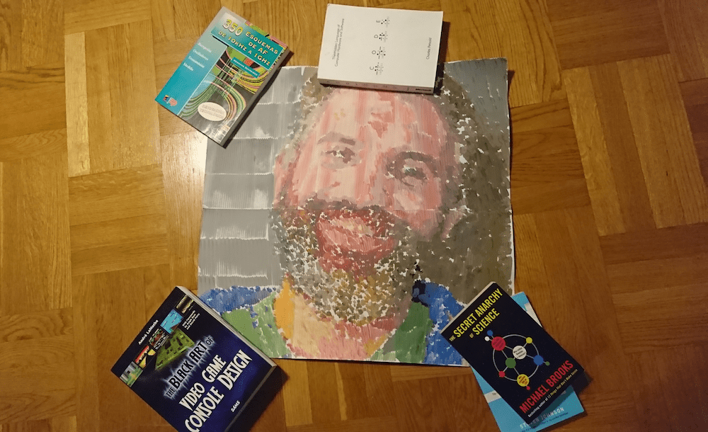
    The process of making this portrait was not exactly short, the robot moves back and forth every couple of brush strokes to get some more paint. The colors are created by dipping into small containers. Imagine a CNC of sorts moving on the X-Y plane and making a small movement with the brush in order to make a mark on the canvas. My portrait is made of several A4 pages glued together, as you can see in the picture. In total it takes several hours to produce a portrait like this one.

    You can see the first traces made by the machine while painting my portrait in the following video.

    [youtube https://www.youtube.com/watch?v=-eHGRJ1dQ7I?feature=oembed&w=500&h=281]

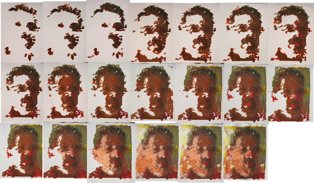
    The painting robot was built by Jose Salatino, a painter gone roboticist that used to go around making portraits to famous musicians and giving the paintings away to them. He told me that this is how he started in the art world. At some point he wanted to bring together his life passion with his hobby (electronics) and got interested into painting robots (seems like there is a whole niche there I haven’t explored yet) and realized that very few people were really using a painter’s technique to mix the colors. That triggered him into learning more about machines in general, and machines that could paint in particular.

    [Jose’s self portrait process, image courtesy of Jose Salatino]

    The machine itself

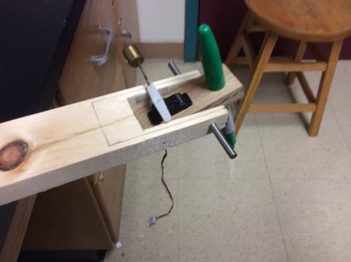
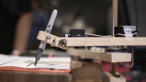
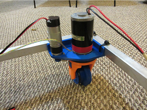
    The painter robot, which I came to call Van Gogh because of its painting style, is a two-axis machine that can be programmed to move all over the canvas. The machine uses the technique of creating a color by mixing first basic pigments (blue, yellow, red) and then dipping the brush again into one of a series of containers grading from white to black. This is, Jose told me, how he would mix the paint: first dip into the different containers of basic color (e.g. to make a bright green, need to dip once in blue and maybe three times in yellow), second assign the luminosity by dipping into a certain gray color. When asked about whether the paint containers would not get dirty by doing so, Jose replied that so it goes when painting for him. The colors get dirty on the palette and you need to keep on adding new color. And this is when I realized that I was totally over engineering the project in my head when I tried to imagine how I would do it. Check the robot in action in the following video.

    [youtube https://www.youtube.com/watch?v=oVwRXeMYCKI?feature=oembed&w=500&h=281]

    Note the sponge used to clean the brush before reloading it with paint, yet another master move, in my opinion. You can read more about the machine by visiting the project’s write-up here

    The contest Jose is participating in

    Jose has entered a robotics painting contest with the works made by his robot. One of the proposed pieces is actually my portrait. 🙂 

    The 2018 “3rd Annual” International Robotic Art Competition’s goal is to challenge teams to produce something visually beautiful with robotics – that is, to have a robot use physical brushes and paint to create an artwork.

    Jose’s robot is all about brushes, as I already told you. And he is all for the competition, for which he teamed up with his kids who learned everything that was needed to make the robot paint as it does. The idea is that, in case he won this contest, 90% off the $100.000 USD prize would be donated to an NGO in the US. Are you interested in art? More specifically, are you into robotic art? Then visit the contest’s site, register, and vote for your favorite pieces. If you voted for Jose’s work, you could also help him choose an NGO where to give the money away: Red Cross, Black Girls Code, Learn2Teach-Teach2Learn… as he lives in Barcelona, he doesn’t really know who he would give the price to in the US. Jose is open to suggestions, but remember he needs your vote first!

    Check the whole contest here and Jose’s entry here.

    Read more about Jose

    If you are interested in reading more about Jose’s project, his daughter, Flor, made a very nice interview and reflection about the role of the artist when there is a machine making the work. This is something I bet many readers were wondering by now: “if the machine paints it, who is the one to be credited, the machine or the person making the machine?” In my opinion, and since I am one of the models, I think we–the models giving away our image–should be also getting some credit, or? (Note: this last sentence was a joke!)


    Website: LINK

  • U.S. Army Develops 3D Printed Soft Robotics Inspired by Invertebrates

    U.S. Army Develops 3D Printed Soft Robotics Inspired by Invertebrates

    Reading Time: 3 minutes

    After studying the mechanisms of invertebrates in nature, U.S. Army researchers have developed 3D printed soft robotics that can traverse difficult landscapes and squeeze into crowded spaces. 

    A joint project between the U.S. Army Research Laboratory (ARL) and the University of Minnesota (UMN) is exploring 3D printed soft robotics that can squeeze into tight spaces and travel around obstacles, essentially acting like invertebrates.

    Previously, the U.S Army has had to settle for rigid and inflexible robots, making it difficult to maneuver in crowded places and congested environments.

    The current limitations of military robots include a lack of dynamic flexibility, which is due to their rigid components. Additionally, these robots also require the U.S. Army to activate complex mechanisms and electrical circuits.

    And so, the ARL and UMN are using tunable materials to develop the first soft robotic prototypes. The team is also able to modify the structural flexibility, morphology, and dynamic actuation of the 3D printed robot.

    The final 3D printed prototype is the first of its kind, able to perform bending motions and squeeze into tight spaces.

    “Successful stealthy maneuvering requires high structural flexibility and distributive control to sneak into confined or restricted spaces, operate for extended periods and emulate biological morphologies and adaptability,” explained Dr. Ed Habtour, an ARL researcher who studies nonlinear structural dynamics.


    (a) Schematic of a soft actuator device (left) and exploded view of the device and constituent material layers. (b) Schematic of depositing (3D printing) hydrogel on the surface of a silicone layer after surface treatment and under UV light exposure. (c) Printing of the ionic hydrogel on the passive layer after surface treatment, final 3D printed DEA, and microstructure image of the device cross-section. (Source: US Army)

    Using Nature to Advance 3D Printed Soft Robotics

    During the first phase of research, the UMN team observed different methods that would allow them to “emulate the locomotion of invertebrates”. By doing so, they gained insight into soft distributed actuation circuitries that can perform high bending motions without skeletal support.

    After looking at mechanisms in nature boast flexible abilities, the team developed a customized 3D printing platform and mathematical model to study and predict these optimal actuation mechanisms. UMN then 3D printed the first actuation circuitries using soft and stretchable materials that have mechanical features inspired by nature.

    “The research findings represent an important stepping stone towards providing the Solider an autonomous freeform fabrication platform – next-generation 3-D printer, which can print functional materials and devices – to generate soft actuators and potentially tetherless soft robots on demand, on the fly and at the point of need,” Habtour said.

    Not only are the 3D printed actuators incredibly flexible, they can also be manufactured without post-processing and are extremely easy to use. In the next phase of the project, the team plans to focus on the interplay of internal interfaces and interaction kinetics observed in biological systems.

    The current research has been published in Extreme Mechanics Letters.


    Dr. Ed Habtour at ARL.

    Source: U.S. Army

    License: The text of „U.S. Army Develops 3D Printed Soft Robotics Inspired by Invertebrates“ by All3DP is licensed under a Creative Commons Attribution 4.0 International License.

    Subscribe to updates from All3DP

    You are subscribed to updates from All3DP

    Website: LINK

  • Soft Robotic Gripper with Gecko Inspired Adhesives

    Soft Robotic Gripper with Gecko Inspired Adhesives

    Reading Time: 3 minutes

    A new class of adhesives — inspired by the mighty Gecko — have been developed by researchers in California to help soft robotic fingers get a better grip

    A team of researchers have developed a robotic gripper that combines the adhesive properties of gecko toes and the adaptability of air-powered soft robots. It has the ability to grasp a wider variety of objects than current robotic grippers. It’s capable of lifting up to 45 lbs and can be deployed in a wide range of settings, from factory floors to the International Space Station.

    Where did the gecko inspiration come from? Geckos are among the best climbers in the natural world because of a sophisticated gripping mechanism on their toes. Each toe has millions of microscopic hairs, about 20 to 30 times smaller than a human hair, that allow it to climb on virtually any surface. The hairs end in tiny nanostructures that interact at the atomic level with molecules on the surface the gecko is trying to grip.

    Previously, researchers at Stanford University and the NASA Jet Propulsion Laboratory recreated this same mechanism with a synthetic material called a gecko-inspired adhesive. This material was used primarily on flat surfaces like walls.

    In the latest work, researchers collaborated with engineers at the University of California San Diego. The team coated the fingers of a soft robotic gripper with the gecko adhesive, allowing it to get a firmer grasp on a wide range of objects, including pipes and mugs, while still being able to handle rough objects like rocks.

    The gripper can also grasp objects in various positions, for example gripping a mug at many different angles.

    Soft Robotic Gecko Gripper is State of the Art

    Researchers demonstrated that the gripper could grasp and manipulate rough, porous and dirty objects, such as volcanic rocks—a task that is typically challenging for gecko adhesives. It also was able to pick up pieces of large, cylindrical pipe—a task typically difficult for soft robotic grippers.

    “We realized that these two components, soft robotics and gecko adhesives, complement each other really well,” says Paul Glick, author of the the paper and a PhD student in the Bioinspired Robotics and Design Lab at the Jacobs School of Engineering at UC San Diego.

    The gecko adhesives are made in a three-step process. An original master gecko adhesive mold with millions of microscopic structures is made in a clean room using a photolithography process. Then, wax copies of the master mold can be made at low cost.

    The researchers then can make as many copies of the adhesive sheets from the wax mold as they often as want by using a process called spin coating. This allows them to make 10 to 20 adhesive sheets in under an hour.

    Meanwhile, the soft robotic gripper itself is cast in 3D printed molds and is made from silicone-based rubber.

    Next steps in the research include developing algorithms for grasping that take advantage of the adhesives, and investigating the use of this gripper for zero-gravity and space operations.

    Researchers will present their findings at the 2018 International Conference on Robotics and Automation running from May 21 to 25 in Brisbane, Australia.

    gecko gripper
    gecko gripper

    Source: UC San Diego News Center

    License: The text of „Soft Robotic Gripper with Gecko Inspired Adhesives“ by All3DP is licensed under a Creative Commons Attribution 4.0 International License.

    Subscribe to updates from All3DP

    You are subscribed to updates from All3DP

    Website: LINK

  • SoFi, the underwater robotic fish

    SoFi, the underwater robotic fish

    Reading Time: 2 minutes

    With the Greenland shark finally caught on video for the very first time, scientists and engineers are discussing the limitations of current marine monitoring technology. One significant advance comes from the CSAIL team at Massachusetts Institute of Technology (MIT): SoFi, the robotic fish.

    A Robotic Fish Swims in the Ocean

    More info: http://bit.ly/SoFiRobot Paper: http://robert.katzschmann.eu/wp-content/uploads/2018/03/katzschmann2018exploration.pdf

    The untethered SoFi robot

    Last week, the Computer Science and Artificial Intelligence Laboratory (CSAIL) team at MIT unveiled SoFi, “a soft robotic fish that can independently swim alongside real fish in the ocean.”

    MIT CSAIL underwater fish SoFi using Raspberry Pi

    Directed by a Super Nintendo controller and acoustic signals, SoFi can dive untethered to a maximum of 18 feet for a total of 40 minutes. A Raspberry Pi receives input from the controller and amplifies the ultrasound signals for SoFi via a HiFiBerry. The controller, Raspberry Pi, and HiFiBerry are sealed within a waterproof, cast-moulded silicone membrane filled with non-conductive mineral oil, allowing for underwater equalisation.

    MIT CSAIL underwater fish SoFi using Raspberry Pi

    The ultrasound signals, received by a modem within SoFi’s head, control everything from direction, tail oscillation, pitch, and depth to the onboard camera.

    As explained on MIT’s news blog, “to make the robot swim, the motor pumps water into two balloon-like chambers in the fish’s tail that operate like a set of pistons in an engine. As one chamber expands, it bends and flexes to one side; when the actuators push water to the other channel, that one bends and flexes in the other direction.”

    MIT CSAIL underwater fish SoFi using Raspberry Pi

    Ocean exploration

    While we’ve seen many autonomous underwater vehicles (AUVs) using onboard Raspberry Pis, SoFi’s ability to roam untethered with a wireless waterproof controller is an exciting achievement.

    “To our knowledge, this is the first robotic fish that can swim untethered in three dimensions for extended periods of time. We are excited about the possibility of being able to use a system like this to get closer to marine life than humans can get on their own.” – CSAIL PhD candidate Robert Katzschmann

    As the MIT news post notes, SoFi’s simple, lightweight setup of a single camera, a motor, and a smartphone lithium polymer battery set it apart it from existing bulky AUVs that require large motors or support from boats.

    For more in-depth information on SoFi and the onboard tech that controls it, find the CSAIL team’s paper here.

    Website: LINK

  • Petoi: a Pi-powered kitty cat

    Petoi: a Pi-powered kitty cat

    Reading Time: 3 minutes

    A robot pet is the dream of many a child, thanks to creatures such as K9, Doctor Who’s trusted companion, and the Tamagotchi, bleeping nightmare of parents worldwide. But both of these pale in comparison (sorry, K9) to Petoi, the walking, meowing, live-streaming cat from maker Rongzhong Li.

    Petoi: OpenCat Demo

    Mentioned on IEEE Spectrum: https://spectrum.ieee.org/automaton/robotics/humanoids/video-friday-boston-dynamics-spotmini-opencat-robot-engineered-arts-mesmer-uncanny-valley More reads on Hackster: https://www.hackster.io/petoi/opencat-845129 优酷: http://v.youku.com/v_show/id_XMzQxMzA1NjM0OA==.html?spm=a2h3j.8428770.3416059.1 We are developing programmable and highly maneuverable quadruped robots for STEM education and AI-enhanced services. Its compact and bionic design makes it the only affordable consumer robot that mimics various mammal gaits and reacts to surroundings.

    Petoi

    Not only have cats conquered the internet, they also have a paw firmly in the door of many makerspaces and spare rooms — rooms such as the one belonging to Petoi’s owner/maker, Rongzhong Li, who has been working on this feline creation since he bought his first Raspberry Pi.

    Petoi Raspberry Pi Robot Cat

    Petoi in its current state – apple for scale in lieu of banana

    Petoi is just like any other housecat: it walks, it plays, its ribcage doubles as a digital xylophone — but what makes Petoi so special is Li’s use of the project as a platform for study.

    I bought my first Raspberry Pi in June 2016 to learn coding hardware. This robot Petoi served as a playground for learning all the components in a regular Raspberry Pi beginner kit. I started with craft sticks, then switched to 3D-printed frames for optimized performance and morphology.

    Various iterations of Petoi have housed various bits of tech, 3D-printed parts, and software, so while it’s impossible to list the exact ingredients you’d need to create your own version of Petoi, a few components remain at its core.

    Petoi Raspberry Pi Robot Cat — skeleton prototype

    An early version of Petoi, housed inside a plastic toy helicopter frame

    A Raspberry Pi lives within Petoi and acts as its brain, relaying commands to an Arduino that controls movement. Li explains:

    The Pi takes no responsibility for controlling detailed limb movements. It focuses on more serious questions, such as “Who am I? Where do I come from? Where am I going?” It generates mind and sends string commands to the Arduino slave.

    Li is currently working on two functional prototypes: a mini version for STEM education, and a larger version for use within the field of AI research.

    A cat and a robot cat walking upstairs Petoi Raspberry Pi Robot Cat

    You can read more about the project, including details on the various interactions of Petoi, on the hackster.io project page.

    Not quite ready to commit to a fully grown robot pet for your home? Why not code your own pixel pet with our free learning resource? And while you’re looking through our projects, check out our other pet-themed tutorials such as the Hamster party cam, the Infrared bird box, and the Cat meme generator.

    Website: LINK

  • Meet CIMON: The Floating AI That Will Live on the International Space Station

    Meet CIMON: The Floating AI That Will Live on the International Space Station

    Reading Time: 3 minutes

    Airbus is using artificial intelligence from IBM to create an AI robot that will live on the International Space Station. This 3D printed mission and flight assistance system is called the Crew Interactive Mobile Companion, also known as CIMON.

    Astronauts aboard the International Space Station (ISS) will soon have their own AI-based mission and flight assistance system to provide support to the crew. The European aerospace company Airbus is working in cooperation with IBM to develop CIMON (Crew Interactive MObile CompanioN). This is an AI-based assistant developed for the DLR Space Administration.

    CIMON is the size of a medicine ball and weighs around 5 kg. Airbus uses plastic and metal 3D printing to create the structure of the AI robot. Using Watson AI technology from the IBM cloud, CIMON will have a face, voice, and loads of artificial intelligence.

    “In short, CIMON will be the first AI-based mission and flight assistance system. We are the first company in Europe to carry a free flyer, a kind of flying brain, to the ISS and to develop artificial intelligence for the crew on board the space station,” said Manfred Jaumann, Head of Microgravity Payloads from Airbus.

    This unique AI system will help astronauts with routine work, displaying procedures and even offering solutions to problems. Astronaut Alexander Gerst is planning to test CIMON on the ISS during the European Space Agency’s Horizons mission. This expedition will take place between June and October 2018.

    Once CIMON floats its way aboard the ISS, crew members will have an assistant to make everyday tasks easier to complete. The AI-based mission and flight assistance system will aim to increase efficiency, facilitate mission success, and improve security. According to Airbus, CIMON will also act as an early warning system for technical problems on the spacecraft.


    CIMON Astronaut Assistance System to Become the Latest Member of the ISS

    The Watson-based AI trains itself with voice samples and photos of Gerst. The astronaut also played a role in selecting CIMON’s screen face and computer voice, making it easier for the duo to become friends. The AI system is also knowledgable about the procedures and plans of the Columbus module of the ISS.

    CIMON is still learning how to orientate itself and move around. Additionally, it’s using WATSON AI technology to accumulate information and recognize its human co-workers. Once testing is complete, Gerst will take on three different space missions with the AI-based system.

    Together, the astronaut and CIMON will experiment with crystals, work together to solve the Rubik’s cube, and also perform a complex medical experiment with an ‘intelligent’ flying camera. At first, the AI system will have a limited range of capabilities. Eventually, it will be used to examine social interaction between man and machine, or more specifically, between astronauts and AI systems equipped with emotional intelligence.

    The project was commissioned by the Bonn-based DLR Space Administration back in August 2016. Currently, CIMON is being worked on by a project team of over 50 people, including members from Airbus, DLR, IBM, and the Ludwig-Maximilians-Universität in Munich (LMU).

    In the future, Airbus believes that this type of AI system can make an impact in hospitals and social care. For now, CIMON will focus on assisting astronauts with routines, and interacting with them on a social level. And, as long as the AI system doesn’t undergo some evil HAL 9000-like evolution, this intelligent robot should make life easier for those residing on the ISS.


    Source: Airbus


    License: The text of „Meet CIMON: The Floating AI That Will Live on the International Space Station“ by All3DP is licensed under a Creative Commons Attribution 4.0 International License.

    Subscribe to updates from All3DP

    You are subscribed to updates from All3DP

    Website: LINK

  • RoMA: Robotic Modeling Assistant Could be a Better Prototyping Machine

    RoMA: Robotic Modeling Assistant Could be a Better Prototyping Machine

    Reading Time: 3 minutes

    Cornell and MIT are working on a joint project called the Robotic Modeling Assistant (RoMA) which will bring together multiple technologies to create an ultimate prototyping machine. 

    Although 3D printing is certainly improving and streamlining prototyping, researchers from MIT and Cornell want to bring more emerging technologies together to improve such machines.

    The joint project is called the Robotic Modeling Assistant (RoMA). It blends technologies such as augmented reality, 3D printing and robotics. It looks like a robotic arm with a 3D printing pen attached to the end of the arm.

    Team leader Huaishu Peng explains on his website that the machine is an interactive fabrication system. It offers a fast, hands-on, precise modeling experience.

    Essentially, users can create a 3D model in-situ and get hands on with their 3D print using the open, robotic arm. Peng adds:

    “With RoMA, users can integrate real-world constraints into a design rapidly, allowing them to create well-proportioned tangible artifacts. Users can even directly design on and around an existing object, and extending the artifact by in-situ fabrication.”

    Although this process might appear clunky and awkward, it’s an interesting mixture of the emerging technologies. Check out the way it works in the video below:

    Positives and Negatives of the Robotic Modeling Assistant

    Using the augmented reality headset, it’s possible to create the perfect design. While the designer creates a model with the AR CAD editor, the robotic arm will fabricate the object simultaneously.

    The small, basic plastic model created with the 3D printing pen attached to the end can be used as a tangible reference for the maker.

    With this robotic arm, it’s also possible to print on top of other objects as it doesn’t work with a printing bed. Currently, the machine is faster than most FDM 3D printing methods and designers can move the arm more easily.

    “At any time, the designer can touch the handle of the platform and rotate it to bring part of the model forward,” Peng continues.

    “The robotic arm will park away from the user automatically. If the designer steps away from the printing platform, the robotic fabricator can take the full control of the platform and finish the printing job.”

    However, it is more advanced than a 3D printing pen and offers more control. Peng explains that he hopes to see people designing their own everyday objects to suit their needs in the future. Want to find out more? Visit Peng’s website.

    Source: Tech Crunch


    Roma


    License: The text of „RoMA: Robotic Modeling Assistant Could be a Better Prototyping Machine“ by All3DP is licensed under a Creative Commons Attribution 4.0 International License.

    Subscribe to updates from All3DP

    You are subscribed to updates from All3DP

    Website: LINK

  • Playing tic-tac-toe against a Raspberry Pi at Maker Faire

    Playing tic-tac-toe against a Raspberry Pi at Maker Faire

    Reading Time: 2 minutes

    At Maker Faire New York, we met up with student Toby Goebeler of Dover High School, Pennsylvania, to learn more about his Tic-Tac-Toe Robot.

    Play Tic-Tac-Toe against a Raspberry Pi #MFNYC

    Uploaded by Raspberry Pi on 2017-12-18.

    Tic-tac-toe with Dover Robotics

    We came to see Toby and Brian Bahn, physics teacher for Dover High School and leader of the Dover Robotics club, so they could tell us about the inner workings of the Tic-Tac-Toe Robot project, and how the Raspberry Pi fit within it. Check out our video for Toby’s explanation of the build and the software controlling it.

    Wooden robotic arm — Toby Goebeler Tic-Tac-Toe arm Raspberry Pi

    Toby’s original robotic arm prototype used a weight to direct the pen on and off the paper. He later replaced this with a servo motor.

    Toby documented the prototyping process for the robot on the Dover Robotics blog. Head over there to hear more about the highs and lows of building a robotic arm from scratch, and about how Toby learned to integrate a Raspberry Pi for both software and hardware control.

    Wooden robotic arm playing tic-tac-toe — Toby Goebeler Tic-Tac-Toe arm Raspberry Pi

    The finished build is a tic-tac-toe beast, besting everyone who dares to challenge it to a game.

    And in case you’re wondering: no, none of the Raspberry Pi team were able to beat the Tic-Tac-Toe Robot when we played against it.

    Your turn

    We always love seeing Raspberry Pis being used in schools to teach coding and digital making, whether in the classroom or during after-school activities such as the Dover Robotics club and our own Code Clubs and CoderDojos. If you are part of a coding or robotics club, we’d love to hear your story! So make sure to share your experiences and projects in the comments below, or via our social media accounts.

    Website: LINK

  • This Swerve Drive is Almost Entirely 3D Printed

    This Swerve Drive is Almost Entirely 3D Printed

    Reading Time: 2 minutes

    Got a lightweight robot in need of some locomotion? Maker LoboCNC has you covered with this 3D printed swerve drive.

    In light of the upcoming FIRST Robotics Competition (FRC), designer LoboCNC has designed a new swerve drive that is entirely 3D printed.

    A swerve drive is a more maneuverable steering configuration for a robot. It enables robotics operators to steer the robot within a 360 degree radius and rotate it around its own axis. Although swerve drives make life considerably easier for the operator, they are also much harder to design.

    All the more reason to get excited about LoboCNC’s swerve drive, which is almost entirely 3D printed. In addition to the printed parts, all you need are a few metal pieces, belts and motors.

    The swerve drive is considerably lighter and more simplified than commercial versions. It includes a steering bearing using 6mm Airsoft pellets as bearing balls and a twisted timing belt to keep the mechanics even simpler.


    3d printed drive train
    3D printed swerve drive by LoboCNC. (Image: thingiverse)

    3D Printing a Robot’s Drive Train

    With two motors, the system powers both the driving and steering.

    Weighing just 5 lbs, the swerve unit is very lightweight. Thus, its designer recommends only a total weight of 20 lb. In addition, LoboCNC points out that it is very fast at up to 20 feet per second.

    If you’re keen to give it a spin  yourself, a full build guide can be found on the design’s Thingiverse page.

    Following up on preliminary tests to ensure the swerve drive was robust, LoboCNC posted on Thingiverse:

    “So far, we’ve hooked it up and driven it around a little. Everything is operating quite smoothly so far. Next up is getting our full swerve drive control implemented so that we can really beat on it!”

    This isn’t LoboCNC’s first forage into swerve drives. He has previously shown off a 3D printed model developed for the FRC Team 2605 – the Sehome Seamonsters.


    3D printed swerve drive by LoboCNC. (Image: thingiverse)

    Source: thingiverse.com

    Website: LINK

  • Low-tech Raspberry Pi robot

    Low-tech Raspberry Pi robot

    Reading Time: 2 minutes

    Robot-builder extraordinaire Clément Didier is ushering in the era of our cybernetic overlords. Future generations will remember him as the creator of robots constructed from cardboard and conductive paint which are so easy to replicate that a robot could do it. Welcome to the singularity.

    Bare Conductive on Twitter

    This cool robot was made with the #PiCap, conductive paint and @Raspberry_Pi by @clementdidier. Full tutorial: https://t.co/AcQVTS4vr2 https://t.co/D04U5UGR0P

    Simple interface

    To assemble the robot, Clément made use of a Pi Cap board, a motor driver, and most importantly, a tube of Bare Conductive Electric Paint. He painted the control interface onto the cardboard surface of the robot, allowing a human, replicant, or superior robot to direct its movements simply by touching the paint.

    Clever design

    The Raspberry Pi 3, the motor control board, and the painted input buttons interface via the GPIO breakout pins on the Pi Cap. Crocodile clips connect the Pi Cap to the cardboard-and-paint control surface, while jumper wires connect it to the motor control board.

    Raspberry Pi and bare conductive Pi Cap

    Sing with me: ‘The Raspberry Pi’s connected to the Pi Cap, and the Pi Cap’s connected to the inputs, and…’

    Two battery packs provide power to the Raspberry Pi, and to the four independently driven motors. Software, written in Python, allows the robot to respond to inputs from the conductive paint. The motors drive wheels attached to a plastic chassis, moving and turning the robot at the touch of a square of black paint.

    Artistic circuit

    Clément used masking tape and a paintbrush to create the control buttons. For a human, this is obviously a fiddly process which relies on the blocking properties of the masking tape and a steady hand. For a robot, however, the process would be a simple, freehand one, resulting in neatly painted circuits on every single one of countless robotic minions. Cybernetic domination is at (metallic) hand.

    The control surface of the robot, painted with bare conductive paint

    One fiddly job for a human, one easy task for robotkind

    The instructions and code for Clément’s build can be found here.

    Low-tech solutions

    Here at Pi Towers, we love seeing the high-tech Raspberry Pi integrated so successfully with low-tech components. In addition to conductive paint, we’ve seen cardboard laptops, toilet roll robots, fruit drum kits, chocolate box robots, and hamster-wheel-triggered cameras. Have you integrated low-tech elements into your projects (and potentially accelerated the robot apocalypse in the process)? Tell us about it in the comments!

    Website: LINK

  • Google is Currently Building Real Robots, Skynet May be Coming

    Google is Currently Building Real Robots, Skynet May be Coming

    Reading Time: < 1 minute

    Google already has self-driving cars, so self-aware robots with artificial intelligence are the next logical step, right?

    google-skynet

    To kick things off, „Google hopes to create robots for use in industrial settings, like factories [and they’re already] experimenting with delivering packages in urban areas, building upon that existing technology is a no-brainer.“

    Dvice says that „the company has also bought several robotics and AI companies in both the U.S. and Japan and are looking to purchase more. Although, the company calls the robotics division a ‚moonshot,‘ the idea is to get robots on the market as soon as possible. If that’s the case, sign me up for the first robot maid. Who cares if it might become self-aware and bring on the apocalypse?“

    Official Source: http://www.youtube.com/watch?v=fBVDp5eBMhU

    http://www.dvice.com/2013-12-5/skynet-born-google-making-robots