Schlagwort: raspberrypi

  • CutiePi project showcase

    CutiePi project showcase

    Reading Time: 4 minutes

    Having long dreamt of owning a usable Linux-based portable device, a group of enthusiasts set out to create one and the CutiePi tablet was born. Based around a Raspberry Pi Compute Module 3+ Lite and custom carrier board, it features an 8in touchscreen, typical tablet features, and everything you need to make your Raspberry Pi projects portable.

    “We tried to make the CutiePi tablet on par with normal tablets,” says project lead Penk Chan. Penk is a digital nomad wannabe from Taiwan, currently living in Tokyo and working as a principal software engineer at The Qt Company. He’s leading a team of open-source enthusiasts to make the CutiePi tablet happen.

    Penk Chan and fellow open-source enthusiasts in Tokyo created the Raspberry Pi 3+-based CutiePi tablet

    “You’ll find a gyro, a micro-controller for battery and button monitoring, WiFi/Bluetooth and a speaker. We also kept the camera connector and made the remaining GPIO pins available, keeping it hacking friendly.” This will enable it to be used as a launchpad for users’ portable Raspberry Pi projects.

    Making a portable device isn’t easy, though. “It’s not just about the Li-Po battery nor the DC-DC step-up converter,” says Penk. “Those features that we take for granted in consumer electronics, like using the device while it’s charging, reading remaining battery level, or simply detecting a power cable plug-in, are very hard to get right with modules and kits, let alone having a user interface that works. To top it all off, you need a case that houses all the hardware parts and cables.”

    The CutiePi tablet has a Chromium-based web browser and supports all the common touch gestures

    Custom carrier

    The first CutiePi prototype was a cardboard box which housed an off-the-shelf HDMI display, a Raspberry Pi 3, and a power bank. For the second one, they stripped everything from the Raspberry Pi 3 board and soldered flex cables to replace the bulky HDMI connector, with the electronics now housed by a 3D-printed case.

    While most hobby projects would have stopped there, the team went on to create a third prototype, based on a Compute Module 3+ Lite connected to their own custom-designed carrier board. “Using the Compute Module allowed us to make the device a lot thinner, explore other form factors other than the regular Raspberry Pi 3’s, and probably most important of all, it allowed us to mass-produce the CutiePi tablet,” explains Penk.

    Taking around three months to develop, the CutiePi carrier board is based on the reference designs made freely available by Raspberry Pi, and the team have open-sourced their now OSHWA-certified hardware: magpi.cc/CutiePiBoard.

    “At the heart of this project is our love for open-source, and CutiePi is our expression of that affection,” says Penk. “All designs are available under open-source licence, and anyone who wants to produce it, or even build on it to make their next portable project, can freely do so. In fact, we advocate it.”

    Make your own CutiePi: 3D-printable files for the tablet case will be freely available

    Multi-touch display

    The CutiePi tablet features a 1280×800 MIPI-DSI display, with a five-point capacitive multi-touch panel. The user interface is built on top of Raspbian, and you can access the standard Raspberry Pi Desktop via a toggle switch. “When you toggle on over to our made-from-scratch, touch-friendly UI, you will have access to the CutiePi shell, including a WiFi settings manager, a Chromium-based web browser that supports all the common touch gestures, an on-screen keyboard with multiple languages layout, and a terminal emulator, as part of our software version 1.0 release.”

    A schematic for the CutiePi showing its components and features

    Penk tells us that in the future it will be possible to support native Raspberry Pi apps in the CutiePi shell through use of XWayland, a fully-fledged X server implementation for the Qt Wayland Compositor being used for the display.

    It all sounds very promising and, with the hardware parts near finalised, the team are focusing on the design for the final version of the tablet’s enclosure. They have decided to crowdfund the project in order to mass-produce CutiePi, so keep an eye on those crowdfunding sites for it.

    Quick facts

    • CutiePi gets its name from the Qt framework used

    • The carrier board features a sleep/wake button

    • The CutiePi prototype uses a 5000 mAh LiPo battery

    • A 3D-printable case design file will be released very soon

    • A Raspbian image will also be made available for testing

    CutiePi can be used as a ebook device as well as a touchscreen tablet

  • Top 10 advanced Raspberry Pi projects

    Top 10 advanced Raspberry Pi projects

    Reading Time: 3 minutes

    A robotic beast

    A serious robot, the DiddyBorg (£220 / $299) is diddy in name only and a true Raspberry Pi automated monster. Program it, remote-control it, or just have it sitting pretty in your workshop. Your choice.

    DiddyBorg is seriously capable robot you can program and control remotely using your Raspberry Pi

    PiGrrl 2

    DIY handheld gaming

    We’ve covered this project in a previous issue of The MagPi, but this project deserves mentioning again: with some 3D-printed parts, and some ingenious Adafruit PCB parts, you too can make a handheld console (£56 / $60).

    PiGRRL 2: Make your own handheld games console with a case and parts you print yourself

    Retro-cool at home

    This big build by Bob Clagett is incredibly thorough, and shows you how to build a wooden arcade cabinet from scratch, complete with lights and cool art.

    Bob Clagett talks you through making a full-size arcade machine. How retro-cool is that!

    Pinball table

    High score mania

    If an arcade machine is a bit too new for you, how about something a bit more classic and physical like a pinball table? This one repurposes an old bed.

    Turn an old bed into a Raspberry Pi-controlled pinball table. Genius!

    Raspberry Pi classic

    This kind of project is a classic among the community, especially as the mirror software part is so easily done. Building a frame is quite fun and a great first-time carpentry project.

    Turn your Raspberry Pi display into a magic mirror and learn carpentry skills along the way

    Take Raspberry Pi anywhere

    This tiny laptop project allows you to bring your Raspberry Pi with you wherever you want to go, and do some work while you’re there.

    By turning your Raspberry Pi into a tiny laptop you can take it out and aboutou

    Home assistant

    Voice-controlled computer

    A number of big voice services are available on Raspberry Pi. Alexa is one of the easiest to get onto Raspberry Pi, thanks to the excellent AlexaPi software.

    Scan your friends

    This big project is great for showing off at your local Raspberry Jam or maker event. It takes a lot of Raspberry Pi boards and cameras to create the project, but it does capture impressive 3D scans.

    A 3D scanner like you've never seen before, this one makes a great display piece

    3D printer controller

    Futuristic plastic printing

    Have a new 3D printer? How about interfacing it with Raspberry Pi using the amazing OctoPrint? It’s especially helpful if you think of something cool to print while on the go.

    Octoprint adds 3D printing to your Raspberry Pi and offers a web interface for on-the-move updates

    Smart CCTV system

    Recognise your visitors

    CCTV cameras with Raspberry Pi are not too difficult to put together. We like this project as it uses computer vision and face detection to recognise known people as well.

    Face detection and CCTV functions make this a smart security setup

    Learn to program

    Got the tools and the skills to raise a barn and then some, but lacking the ability to print ‘Hello World’? Take a look at our books on controlling electronics with Python and GPIO Zero and learning C.

  • Add internet access to a vintage computer using Raspberry Pi

    Add internet access to a vintage computer using Raspberry Pi

    Reading Time: 7 minutes

    The bulletin boards of the 1980s haven’t died out quite yet, but they have gone online. There’s only a handful of BBSes (bulletin board systems) that you can dial up with your old-time modem.

    If you like the idea of accessing an internet-based BBS from your Atari ST, Amiga, or BBC Micro, then we can use a Raspberry Pi computer to act as a translator. You can even use modern services like Twitter! All we need to do is get Raspberry Pi talking in one of the most popular communications protocols of all time: RS232.

    By interfacing the Raspberry Pi computer UART interface to RS232 and then using WiFi, we bridge the gap between old and new technology

    A little history

    Every Raspberry Pi computer has a form of serial access, which is one of the oldest and simplest ways of communicating with computers. These days you’re more likely to use TCP/IP, the protocol of the internet, to chat to a remote device, but back in the day it was RS232 that ruled the communications world.

    Raspberry Pi circuitry features a further simplified version often referred to UART (universal asynchronous receiver/transmitter) running at 3.3 V, but we can adapt it to ‘full’ RS232 at 12 V so that older computers can handle the signal.

    Cheat #1: If you don’t fancy soldering, you can buy these pre-assembled units (for a few pounds) that can connect to the GPIO

    You’ll need

    Top tip 1: Not just vintage

    This project works well with older PCs. Although they refer to them as COM ports, their 9-pin connectors are really RS232.

    Top tip 2: Be careful of weird wiring

    Do your research on your choice of classic machine. Some, such as the Cambridge Z88, use non-standard wiring to their connectors.

    Study and shop

    To ‘downgrade’ a Raspberry Pi to RS232, we’ll need to build a small circuit to act as a transceiver so the vintage computer can ‘hear’ our virtual modem and the RS232 signals do not fry our delicate Raspberry Pi board. Luckily, all the heavy lifting for such a job can be done by the MAX3232CPC integrated circuit. All you need to do is wire it up, add a few capacitors, and you’ll be BBSing in no time.

    Have a look at the circuit diagram in Figure 1. We’ve deliberately made it larger than it needs to be for simplicity. More experienced makers will be able to reduce it in size if they wish.

    Figure 1: the connector from the solder (rear) side. Use DuPont-style jumper cables to connect the circuit to your GPIO. Make sure you wire up correctly to pins 2 and 3 and ground it

    Soldering the main circuit

    Time to get building. Thankfully, the circuit itself is not very complicated, but it’s also unforgiving, so make sure all the wiring is in the correct place or nothing will work! We recommend starting with the IC socket, then the wiring, followed by the capacitors, finishing with the headers (optional if you’d like to use jumper cables). The result takes the two transmit (TX) and receive (RX) lines from the GPIO and feeds them into the IC. The MAX3232CPC converts the data into RS232 standard and outputs them to the 9-pin D connector and vice versa. Check and double-check everything.

    Add connectors

    Unless you’re going for a permanent setup or looking to make it as low-profile as possible, we recommend using DuPont-style jumper cables to connect the circuit to your GPIO. Which model of Raspberry Pi you use is up to you, but unless you have a specific use case in mind, a Raspberry Pi Zero W is the perfect choice as it’s small and there’s little horsepower required. You will also need to solder up the 9-pin D connector. The diagram (Figure 1) shows the connector from the solder (rear) side. Make sure you wire up correctly to pins 2 and 3 and ground it too.

    Raspberry Pi time

    Your Raspberry Pi Zero W will need a bit of configuration before you can get going. Start with a fresh microSD card with Raspbian Lite (we don’t need a desktop, but feel free to install ‘full’ Raspbian if you wish). This is also a great project for reusing any old low-capacity microSD cards you have, as there’s not much software to install. Once booted up, make sure everything is up to date by running sudo apt -y update && sudo apt -y upgrade. Time to grab a refreshing beverage as Raspbian applies all the latest updates.

    Prepare your virtual modem

    An ‘out of the box’ Raspbian installation isn’t quite ready to go back to the 1980s just yet, so we need to do a little further configuration. From the command line, run sudo raspi-config to start the Raspberry Pi configuration utility. From the top of the menu, start by changing your password (optional, but recommended); then, under Network Options, set your host name (again, optional) and configure WiFi. Finally, under Interfacing Options, enable SSH and Serial. When asked ‘Would you like a login shell’, select ‘Yes’. Now exit the utility and shut down the computer (sudo shutdown).

    Cheat #2: The simplest solution of all is the widely available USB-to-RS232 cables based on the Prolific PL2303 chipset

    Testing time

    Check your circuit board for any short circuits or dry solder joints. Once happy, connect it to the GPIO. There are four connection points: one for 3.3 V (physical pin 1), ground (pin 9), and TX/RX (pins 8 and 10 respectively). We recommend getting an RS232/USB cable and testing with a modern computer first. Connect the 9-pin connectors together and boot your Raspberry Pi. Now, using your favourite Terminal emulator program (we like Serial for macOS), try to connect over RS232. Raspbian’s default settings are 115,200bps (connection speed), eight data bits, no parity, one stop bit (aka 8N1).

    Troubleshooting

    Having problems? RS232 can be a tricky beast as, unless everything is perfect, nothing will work at all. The most common issue will be polarity of the TX and RX lines. For things to work, the RX of the GPIO must be connected via the MAX3232CPC to the TX line of the computer and vice versa.

    Start by checking that your speed is correct and the protocol is set for 8N1. Also try ‘reset’ or ‘send break’ in your terminal emulator, which is sometimes needed to wake up the connection. Finally, try using a null modem cable (which crosses over the lines) or swapping the connectors to pins 8 and 10.

    Get online

    If everything is working, you should now be greeted with the Raspbian terminal login (you might need to press ENTER a couple of times to wake it up). You can now log in as normal. If the connection is behaving, feel free to try it out on a real vintage machine. Some may require adapters to connect (1990s home computers favoured 25-pin D connectors).

    You will probably need to reduce the speed of the connection, as many older computers cannot handle the default 115,200bps. Unless your computer is very old, 9,600bps will probably work. To set the port to this, enter the following from an SSH session:

    sudo stty -F /dev/serial0 9600

    Connect to a BBS

    Almost every BBS is now online and ‚talks‘ using a protocol called Telnet. It is very insecure, sending plain text over the internet and has since been replaced with SSH (Secure Shell). However, many of these services are being run on original equipment that has no support for SSH, so Telnet it is.

    Many classic BBSes are still online, some even supporting PSTN modems. These days, most can be found at the end of an IP address

    The Telnet client software is not installed by default, so run sudo apt install telnet. Once finished, try connecting to the popular Particles BBS (running on an Apple II/e!), by entering:

    telnet particlesbbs.dyndns.org 6400

    Within a few seconds you’ll see a welcome message. After you’ve had a look around, use CTRL+] followed by ‘exit’ to leave Telnet.

    Emulate a classic modem

    If you want a genuine experience, and full compatibility with vintage BBS software, it’s easy to emulate the classic Hayes AT command-set. To install the emulator:

    sudo apt install tcpser

    Before running tcpser, go back into raspi-config, select ‘Interfacing Options’, then ‘Serial’, and answer ‘No’ when asked if you want a login shell to be accessible and then ‘Yes’ if you want the serial port to be enabled. Now start tcpser using SSH:

    tcpser /dev/serial0 -s 9600 -l 7

    (You can change 9600 to be your desired speed).

    Try connecting over serial again and this time you’ll be able to enter AT commands, replacing phone numbers with domain names.

    Polarity is the most common problem encountered when working with RS232. Remember that TX (transmit) goes to RX (receive) and vice versa

    Do more!

    Your original ‘comms’ software should be blissfully unaware that it is talking over the internet. There’s now another web of vintage BBSes to explore on your original machine, but why stop there? The Raspbian repositories are full of command-line software that can be accessed by your classic machine. Tweeting from an old 8-bit is always fun, so why not install ‘t’, a command-line Twitter client (github.com/sferik/t)?

    Of course, you can now do anything in the Raspbian shell that you can in an SSH session, so get your BBC Model B to operate LEDs and switches, or have your Commodore Amiga send Telegram messages!

  • Andrew Suttle interview

    Andrew Suttle interview

    Reading Time: 3 minutes

    “My first Raspberry Jam was CamJam in autumn 2013, when I showed some programs I had written,” Andrew tells us. “I also enjoy developing robots and doing electronics. I first went to the Colchester club run by John Woods in 2016, when I built a robot car using a Raspberry Pi. The Colchester club is run at the university and I like going there very much. The lab we use has all new oscilloscopes and I used them recently with some op-amp circuits. I also built my own oscilloscope from a kit and John Woods helped me get it working, as I had not soldered one of the connections properly. I took my oscilloscope into school and used it there.”

    Andrew isn’t the only young person at the club, either: “Several other children from my school have also gone to the club and I have built projects with them. We made an ‘I ♥ Pi’ team and entered competitions. We also had a ‘Pi Rates’ team. My brother also goes to the club. He is building a security project with Arduino, and I might use some of his ideas in a programming course I am making.”

    While some go there to build physical projects, others learn to code

    What kind of people attend?

    At the moment, it is all children aged 8 to 14 who come along with their parents, but we don’t have set age limits. The youngest children usually want to learn Python; the older children usually have a project of their own that they want to work on. People often drop in for a few sessions and solve a particular problem and then stop attending. We have had some stay for years and they are all from different local schools.

    One boy, Taylor, came regularly until he was 18. He developed several AI projects. He got a scholarship to Cambridge University, and graduates this year.

    Other members have entered competitions and we have had members win in the ‘BigBang’, ‘Pioneers’, and ‘EasternDigital’ competitions. EasternDigital is an ‘adult’ competition for companies and one of the winners three years ago was ten years old; he was too young for their children’s competition!

    What projects have you or other people made there?

    As well as the AI projects I have mentioned, we have had members developing robotic arms. Then there was a flight control system for model aircraft and several robot cars.

    Several children have gravitated towards embedded systems. Two children, Zara and Andrew, developed a plant monitoring system.

    What are you working on at the moment?

    Some of the younger children who are new to the club are doing directed tasks. Samuel, aged eight, and Xingtong, aged eleven, are both working on TicTacToe. But we do very little teaching.

    Some children are doing their own Python projects, with Python always a popular language. Robyn, aged twelve, has made a Mastermind-style game linked with Hangman. Andrew, now aged 14, has developed a version of Conway’s game of life.

    There are also several Arduino projects on the go. Victor, aged eleven, has just finished his security control system which is based on an Arduino Uno and written in C.

    There are always robots. We have a robot arena that is purpose-built for the development of robots, and we have a lot of knowledge and resources to support a robot project. The arena is 100 square metres in area, and has a six-metre-high ceiling to accommodate flying robots.

  • Cheeseborg project showcase

    Cheeseborg project showcase

    Reading Time: 4 minutes

    Making a splash with your final-year university project can be the ideal way to gain the attention of potential employers and land yourself your dream job. Appealing to your lecturers’ and classmates’ stomachs is also a pretty effective way of getting them onside.

    Hearing from Taylor Tabb about the robot project he and friends Mitchell Riek and Evan Hill cooked up for their mechanical engineering degree, it’s little surprise to learn that having graduated in the summer of 2019, he’s already embarked on a fantastic-sounding Raspberry Pi-focused career.

    Taylor Tabb and his Cheeseborg-designing colleagues at Carnegie Mellon knew appealing to fellow students' rumbling tums would win them over

    Taylor studied mechanical engineering at Carnegie Mellon University, exploring how people interact with hardware, and thinks Raspberry Pi is the ideal platform for this. He now works for creative agency DeepLocal, making ‘wild and whimsical’ robots.

    Say cheese!

    “Cheeseborg was born out of our need to concept, design, and build a final prototype of a project in our senior engineering design class,” says Taylor. “As hungry college students awake at hours that it’s often hard to find food, we knew this was our calling – not just for us, but for grilled cheese eaters everywhere.”

    The Raspberry Pi-powered AIY voice kit recognises a request for a grilled cheese sandwich and picks up bread to butter and toast thanks to Arduino Mega

    Cheeseborg is a dedicated, hands-free grilled cheese making robot that will satisfy cheese cravings at all hours. The Google Assistant SDK and AIY Voice Kit provide voice activation. Both “work fantastically with Raspberry Pi 3 Model B+,” says Taylor. Their customised build of Google Assistant, sourced from the AIY Kit and Google Cloud SDK, allowed them to add some personality: you can ask about the weather while awaiting your sandwich.

    Raspberry Pi also triggers its assembly, while motor control circuits and motion are operated by Arduino Mega. Taylor reveals, “We wrote our own code, but also used open-source Arduino libraries,” dictating timings and the motions for each step. Carnegie Mellon’s Department of Mechanical Engineering’s makerspace provided hardware commonly used in 3D printer kits, such as stepper motors and linear motion carriages. However, the acrylic parts were designed and laser-cut by Mitchell, Evan, and Taylor. Impressively, the project cost just $200 to build, and took approximately eight weeks to complete.

    Cheeseborg begins to take shape in the Carnegie Mellon University makerspace

    Taste test

    The team undertook three weeks of customer research to identify grilled cheese preferences. “There was a lot of going back and forth between our build, CAD software, and laser cutter, adjusting parts as we learned more about the mechanics of bread and cheese,” recalls Taylor. They spent days just tuning the grilling time to get the gooeyness and crispiness just right, while experiments in applying the butter resulted in a thoroughly dairy-spattered makerspace.

    Eventually, they went with a spray ‘butter’. “We aimed at the cooking plates and activated just before the bread was moved to be cooked, thus buttering both sides [not to say the rest of Cheeseborg]. In the end, we found if we just spray the grill plates every five [sandwiches] or so, it still is enough to make a crispy, gooey grilled cheese!

    As with all good projects, we had no idea if it was going to work until 4am the morning before it was due, when Cheeseborg popped out its first fully hands-free grilled cheese sandwich.”

    Cheeseborg creators Taylor, Mitchell and Evan at 5am when their invention was finally finished

    Making your own grilled cheese robot

    1. This is the ideal project with which to use Google Assistant in Google’s Raspberry Pi AIY Voice Kit, and the Google Cloud SDK for voice activation. Experiment with phrases to initiate the snack-assembly process.

    Cheeseborg is an ideal project for Google Assistant in the Raspberry Pi-enabled AY Voice Kit

    2. Raspberry Pi now hands over to Arduino. Use Arduino Mega to control the robot that assembles the grilled cheese sandwich once Raspberry Pi instructs it. Open-source Arduino libraries are invaluable here.

    Raspberry Pi hands over to Arduino Mega to control the robot that assembles your tasty snack

    3. Use tongs or suction to pick up slices of bread and add a chute for the snack’s delivery. However, positioning bread to be buttered and adding cheese takes patience.

    Add a chute to deliver the grilled cheese sandwich into the hands of your grateful friends and family

    Interest levels online have been such that Taylor and his colleagues may consider offering a kit version. While he cautions that there’s a huge amount of fine-tuning involved, he says, “If anyone out there is building a grilled cheese robot, we’re more than happy to offer any insights.” Contact him at tabb.me/grilledcheese.

    Warning! Hot mess!

    Gooey butter is messy stuff. Be prepared for your kitchen, as well as your grilled cheese sandwich, to be buttered all over!

    Quick facts

    • Taylor’s first Raspberry Pi project was a ‘not great’ radio telescope

    • Taylor now works with Raspberry Pi almost daily

    • His business card says he’s ’sweeter than Raspberry Pi!’

    • Taylor thinks there’s a whole world of culinary robots to come

    • He recently made a not-so-edible bubble maker

      Hungry students were delighted to encounter Cheeseborg at their final year expo

  • SmartiPi Touch 2 review

    SmartiPi Touch 2 review

    Reading Time: 2 minutes

    The SmartiPi case is designed to work with the 7-inch official Raspberry Pi touchscreen, effectively turning a Raspberry Pi into a (bulky) tablet or fixed monitor. As there’s no real room for rechargeable batteries as standard, it works better in a more fixed environment.

    One of the unique features of the SmartiPi is the interchangeable faceplates on the front of the case. As well as allowing for a Raspberry Pi Camera Module to be mounted inside the case, it enables you to add a Lego-compatible plate. It’s not large, so you can’t do much with it, but it’s a very neat addition nonetheless.

    The SmartiPi Raspberry Pi case looks sleek and compact from the front

    Smart build

    Construction is extremely easy, just requiring you poke some ribbon cables in the right place and fasten and tighten some screws to make sure everything is mounted properly. You can choose little feet for the display, or a foldable stand so you can angle the screen – both are easy to install and even replace. There’s also a little case fan and vented rear panel to keep your Raspberry Pi cool.

    It’s extremely well thought out, and a very handy case if you need a compact ‘Raspberry Pi with screen’ solution that just looks nice.

    SmartiPi's additional case fan and vents can be handy for intensive loads

    Verdict

    The SmartiPi is great case if you need a stationary tablet, although making it mobile might be a little more tricky.

    8/10

  • The biggest Raspberry Pi projects of 2019

    The biggest Raspberry Pi projects of 2019

    Reading Time: 4 minutes

    Raspberry Pi NAS and Samba

    Raspberry Pi 4 introduced improved throughput on the Ethernet port, taking it up to full-fat Gigabit speeds. So it’s perhaps no surprise that building a super-fast NAS (network attached storage) drive was top of the wish-list for many a Raspberry Pi owner.

    Given the popularity of NAS, it’s little surprise to see How to set up Samba also take a top spot on our yearly tutorial list. It’s easy to use a Raspberry Pi as a Samba file server where you can store backups and share files from all the other computers on your network.

    Raspberry Pi 4 USB and Ethernet ports

    SSH and VNC

    SSH (also known as ‘Secure Shell’) is an encrypted networking technology that enables you to manage computers from the command line over a network. It’s a technology that many users are unfamiliar with, until they get a Raspberry Pi and want to get into it from another computer on their network. Our How to setup SSH tutorial gets newbies up and running.

    While SSH is from the command line, VNC enables you to access your Raspberry Pi desktop remotely. Our VNC: Remote access a Raspberry Pi tutorial was another big-hitter in 2019.

    VNC Server displays your IP address and is used to log your Raspberry Pi to VNC Connect so you can access Raspberry Pi via the wider internet

    How to build a Carputer (car computer)

    And now we’re into the biggest project of 2019. How to build a Carputer (car computer) with your Raspberry Pi and touchscreen. Raspberry Pi makes a fantastic car computer, thanks to its small footprint and fast processing power: it’s better than many computers found in commercial cars.

    Car Computer

    Build a Raspberry Pi cluster computer

    Cluster computing is one of the most modern programming techniques around. There’s strength in numbers and some of the world’s most powerful computers are built of hundreds, in not thousands, of inexpensive systems.

    PJ Evan’s Build a Raspberry Pi cluster computer tutorial shows you how to link up four Raspberry Pi boards to build a powerful cluster. This can be used to create a more powerful server (such as the one running this website) or used to learn cluster computing programming techniques.

    Cluster computing is a reasonably niche activity, but our readers are a pretty clever bunch so we’re going to hope many of them find a use for this.

    Each Raspberry Pi in the cluster is known as a node and works in parallel with the others to produce faster results than they could individually

    The Interactive tabletop RPG table

    Plunder dungeons and slay dragons in digital style with this simple TV conversion project for all your role-playing game needs. The MagPi magazine’s very own Rob Zwetsloot built this touchscreen RPG companion device, and it turns out a lot of readers want to build one too.

    dndmain-web

    Steam Link on Raspberry Pi

    Gamers rejoiced when Steam released Steam Link. This software enables you to turn a Raspberry Pi into a streaming console, enabling you to play PC games remotely. The games run on PC, and are typically streamed to a Raspberry Pi sitting underneath a television. Our Steam Link tutorial shows you how to set up Steam Link on a Raspberry Pi 4.

    Steam Link

    Code Pac-Man in Python

    It’s one of the most famous games ever made, and Pac-Man in Python is a great learning tool. It’s no surprise that many gamers want to recreate games in Python and our sister magazine, Wireframe recently released a whole book – Code the Classics – dedicated to just that.

    <img src="https://www.blogdot.tv/wp-content/uploads/2020/01/the-biggest-raspberry-pi-projects-of-2019-4.jpg" alt="

    Code your own Pac-Man game in Python

    „>

    ANPR: Car Spy Raspberry Pi

    Automatic number plate recognition is used by the police to match cars against a huge database. We don’t have that database, but OpenCV can be used to detect car number plates and detect your own car. It wasn’t long ago that ANPR technology was extremely expensive to purchase, and Raspberry Pi makes it available to everybody. And our ANPR: Car Spy Raspberry Pi project certainly seems to have sparked some interest.

    <img src="https://www.blogdot.tv/wp-content/uploads/2020/01/the-biggest-raspberry-pi-projects-of-2019-5.jpg" alt="

    Our target. The software does a great job of recognising number-plates from different heights and angles

    „>

    Build a Raspberry Pi telephone exchange

    Transform your humble home phone line into a feature-packed PBX (private telephone exchange) with Raspberry Pi and Asterisk. Many readers might just want to experiment with telephone exchange technology at home, but there’s a good business case for learning how to do this: professional PBX systems cost thousands of pounds.

    <img src="https://www.blogdot.tv/wp-content/uploads/2020/01/the-biggest-raspberry-pi-projects-of-2019-6.jpg" alt="

    Build a VoIP Telephone Exchange with Raspberry Pi

    „>

    The ZX Spectrum Next

    ZX Spectrum Next has been in development for quite some time, but has only been on our website for a few weeks. In that time it’s become one of the biggest stories of the year. David Crookes investigated the development of the ZX Spectrum Next computer with a FPGA (field programmable gate array) using Raspberry Pi Zero as an extender to act as a virtual tape drive, sound interface and 3D graphics enhancer.

    The ZX Spectrum Next contains a Z80 processor on an FPGA, 1MB of RAM expandable to 2MB,
hardware sprites, 256 colours, RGB/VGA/HDMI video output, and three AY-3-8912 audio chips

  • Enviro pHAT Raspberry Pi review

    Enviro pHAT Raspberry Pi review

    Reading Time: 2 minutes

    See also: Enviro + review

    The Enviro (£28/$30. Pimoroni)also features the same slimline pHAT form factor to match the size of a Raspberry Pi Zero, although it can be used with any Raspberry Pi model.

    Sensing the world

    The Enviro’s BME280 weather sensor monitors temperature, barometric pressure, and humidity. As on the Enviro +, this has been positioned at the left edge of the board, away from Raspberry Pi’s CPU, and there’s even a little smile-shaped slot around it to help reduce heat radiated through the board. Even so, you’ll need to adjust its temperature reading for accuracy (by measuring that of the CPU itself and deducting a factor of it).

    A smartphone-style LTR-559 light and proximity sensor detects the ambient light level and also proves handy as a substitute for a push-button when you put your finger on it. The board’s tiny MEMs microphone measures sound levels, useful for monitoring noise pollution, and can also be used to record audio.

    At the time of writing, most of the code examples provided with the Python library are aimed at the Enviro + Air Quality board. However, it’s easy to edit the code for missing sensors from the all-in-one example to get it showing rolling graphs for temperature, pressure, humidity, and light level on the LCD. There are also a couple of examples that make use of the mic to plot noise levels and frequencies.

    If you don’t need to test air quality and just want a simple environmental sensor with a built-in display, the Enviro is ideal. The light sensor could also come in handy for use in IoT setups, such as to trigger your lights to come on when the light level falls below a certain level.

    If you also require motion/direction sensing, the original Enviro pHAT is still available (albeit without the mini LCD).

    The reverse of the Enviro for Raspberry Pi

    Specs

    • Built-in sensors: BME280 temperature/pressure/humidity, LTR559 light/proximity, SPH0645LM4H-B noise

    • Display: 0.96-inch colour LCD (160×80)

    • Dimensions: 65×30×8.5 mm

    Verdict

    Lacks the gas sensor of the Enviro + Air Quality board, but features the same mini LCD screen to display your environmental data without a monitor.

    8/10

  • Organnery pipe organ

    Organnery pipe organ

    Reading Time: 3 minutes

    Raphaël tell us that he increasingly found components for first-generation digital pipe organs – many of which are installed in churches across the world – to be either obsolete, expensive, or simply unobtainable, threatening to consign many an instrument to the scrap-heap.

    The solution has been Organnery, a project to to strip the organs of their old electronics and replace them with something new. “After some thoughts and calculations, we came up with a method that would retain the console, keyboard, and controls and instead make use of a small, affordable, and efficient single-board computer,” he says.

    The chosen device was a Raspberry Pi, selected because of its worldwide availability, strong development community, and affordable price. It offered a perfect way of bringing pipe organs back to life so that they can be played as before, while allowing modern options such as a touchscreen.

    “There are lots of good HATs available covering sound output, MIDI, and control interfaces,” says Daniel James, boss of 64 Studio, the company tasked with creating the software.

    Digital organs have been used in place of pipe organs within churches for a while, but damp and the scarcity of spare parts mean they’re not lasting as long

    Fine tuning the Organnery

    As such, Daniel and colleague Chris Obbard began to work on a customised Debian GNU/Linux image called Organnery (GitHub link) that made use of the open-source classical organ modelling software Aeolus and Raspberry Pi’s capabilities. With eleven different temperaments, variable tuning, three or more manuals, and a pedal board, as well as MIDI in/out control and the flexibility to play different sounds, a personalised experience is possible.

    “Organnery needed to be set up as a single-use appliance, and the requirements came directly from the organists we’ve been working with to refine the system,” Daniel says. “We made adjustments to the Aeolus source code as well as to supporting programs. These included Mididings, a scriptable MIDI router and processor written in Python.”

    Daniel also created minimal system images based on Debian Buster using Dibby, which is a collection of scripts that leverage the distro’s packaging tools. “This approach was a far leaner and more reproducible way to build appliances than starting from a standard image and stripping the system down,” Daniel says.

    The Aeolus software allows a collection of stops to be saved to a USB memory stick for each organist

    Retro hits

    So what’s the verdict? “Organnery offers a major sound upgrade since the sound produced by the Aeolus software is of a much better quality than digital electronics from the 1980s,” Raphaël says. “It gives the organ player access to new ‘pipes’ and complete control over sound placement in space, from a standard stereo system up to 3D Ambisonic diffusion.”

    Most Organnery systems are being retro-fitted into existing organs, but the system can be built from scratch using standard and affordable MIDI hardware. “Some of the smaller organs made for the domestic market have a five-pin MIDI Out socket and can be obtained for next to nothing,” Daniel explains. “Aeolus and Organnery can also make learning the classical organ much more accessible than it has been in the past.”

    Even so, bringing organs back to life, complete with the original woodwork and physical controls, is perhaps most satisfying. “Church organ consoles are also often made of expensive hardwoods so we are saving trees,” Daniel says. For organists used to the age-old interface of their instruments, that’s sure to be extra music to their ears.

    The MIDI switches of an organ are being retro-fitted with new electronics, powered by Raspberry Pi

  • ZX Spectrum Next Raspberry Pi project showcase

    ZX Spectrum Next Raspberry Pi project showcase

    Reading Time: 4 minutes

    “For me, the goal has been to encourage a new generation of bedroom coders,” says legendary games developer Jim Bagley, who is among a group of Spectrum fans behind the project. Jim has been programming games professionally for the past 31 years and is a key member of the specnext.com team dedicated to bringing back the ZX Spectrum.

    Jim Bagley is a legendary games developer and ones of the leading lights behind bringing back the ZX Spectrum

    With 3113 Kickstarter backers handing over £723,390 in cash, many others potentially share that dream.

    Work has certainly progressed well. “When the Next was first announced three years ago, it was intended to be a normal Spectrum with an SD card and a Raspberry Pi Zero as an extender,” Jim explains. “Raspberry Pi was going to be used to add extra features such as hardware sprites and hardware scrolling so that newcomers would find it easier to code the computer and get the wow factor of getting something running instantly on the screen.”

    During the Kickstarter campaign, however, a large field-programmable gate array (FPGA) was announced for the Next – a configurable integrated circuit which allowed the hardware sprites, scrolling, and other advanced features to be incorporated within the machine itself. “It freed up Raspberry Pi Zero to do something else,” Jim says. So the developers began to play around.

    It will work with CRT and VGA monitors, as well as more modern screens, thanks to the support of a HDMI output

    Load and run

    One of the initial ideas was to recreate the feel of loading a game from tape – generating the series of scratchy, beepy, high-pitched noises which could be heard as a program was ingested into the computer. On the original hardware, this was accompanied by a loading image slowly building on the screen and animated stripy borders.

    Rather than have Next users connect a cassette deck, the developers had a cunning plan. “We thought it would be a good idea to have commands sent back and forth between the Next and Raspberry Pi Zero,” Jim says. This developed into a tool allowing a TZX file (a format that stores an exact copy of a ZX Spectrum tape) to be uploaded from an SD card to Raspberry Pi Zero. By sending it back down to the new-gen Speccy through an audio-in pin, the Next would be fooled into thinking it’s loading a cassette. “It gives the original feeling of loading from tape,” Jim affirms.

    The ZX Spectrum Next contains a Z80 processor on an FPGA, 1MB of RAM expandable to 2MB,
hardware sprites, 256 colours, RGB/VGA/HDMI video output, and three AY-3-8912 audio chips

    Are you there, SID?

    Having a Raspberry Pi Zero accompanying the Next has also enabled other audio delights. A Sound Interface Device (SID) emulator has been developed that allows audio created for Commodore’s SID programmable sound generator chip to be played on the Next.

    It will also be possible to enjoy Atari ST audio files and tunes created using music trackers on the Commodore Amiga. “We can send the audio through a GPIO pin and it goes straight to the FPGA, where it’s mixed with the audio of the Next,” Jim explains. To achieve all of this, the developers have used DietPi to create a new OS called NextPi. “It remains a fully functioning Raspberry Pi Zero that is running at the same time as the Next, but we wanted the Next to be more in control.”

    Games made specially for the Next are saved as .NEX files which load directly to the computer via a
SD card. Since the games are 768kB in size (or 1792kB for the 2MB models), it would take too long to route them via Raspberry Pi Zero

    The most recent extra use for the Next’s Raspberry Pi Zero is the ability to connect the latter to its own display. “It’s possible to send screens to Raspberry Pi Zero so that you can have a dual screen,” Jim says. “This means you could have a game being played on the Next, with a global map or stats shown via Raspberry Pi Zero.”

    The team is now looking to get USB controllers to work via Raspberry Pi Zero, allowing them to be read by the Next. “We’d also like Raspberry Pi Zero to help with 3D maths so you can take vertices, have them rotated, and passed back,” Jim says. In the meantime, the team is readying the new computer for a January release and a new Kickstarter is being planned for those who didn’t pledge the first time around. We’re certainly looking forward to seeing where it – and RaspberryPi – goes next.

    Rather than simply emulate the Spectrum, the Next uses a field-programmable gate array chip that acts as a Z80 processor with the addition of advanced features

    Raspberry Pi loading

    1. Games in the file format TZX – a tape format used for preservation purposes – need to be saved on to an SD card and inserted into the ZX Spectrum Next. 

    Games are installed on the ZX Spectrum Next from an SD Card

    2. A game can then be selected via the Next computer’s built-in Browser mode. Raspberry Pi Zero will be instructed to load the game’s data from the SD card.

    Select a game in the ZX Spectrum Next’s Browser mode and Raspberry Pi Zero instructs it to load from the SD card.

    3. Raspberry Pi Zero sends the data back to the ZX Spectrum Next as audio and this generates the once-familiar loading noise and loading screen ahead of the game running.

    Raspberry Pi sends data to the ZX Spectrum as audio, resulting in the familiar electronic loading sounds of 80s computer games

    Looking for some more retro gaming joy? You could always: code your own retro games console, build your own retro game with PICO-8, indulge in an entire issue of The MagPi dedicated to retro gaming or this incredible hardback ‚Code The Classics‘ guide, brand-new from Raspberry Pi Press for a more £12?

  • 50 Raspberry Pi tips and tools in The MagPi magazine issue 89

    50 Raspberry Pi tips and tools in The MagPi magazine issue 89

    Reading Time: 2 minutes

    A lot of projects need specific tools, and there’s a lot out there to choose from. Raspberry Pi maker Mark Vanstone takes a look at the 50 best physical and digital tools you can use to build projects.

    Click here to buy The MagPi magazine issue #89

    50 Raspberry Pi 4 tips & tools

    Raspberry Pi kit & gadget guide

    Quickly do more with your Raspberry Pi with kits and accessories. Our guide to the best add-ons, HATs, starter kits, robot builds and accessories has everything you need.

    Raspberry Pi kit & gadget guide

    Add internet to a classic computer

    Missing the days of dial-up? Build an interface to the modern world for an old computer (an Atari ST, in our case) using a RS232 receiver.

    Add internet to a classic computer

    Design a 3D printer pendant with BlocksCAD

    BlocksCAD is a 3D model editor that runs just fine on the faster Raspberry Pi 4. In this tutorial we look at how to use this Scratch-like language to design a pendant for a 3D printer.

    Design a 3D printer pendant

    Aquatic Mini Observation System

    We’ve got the best community projects every month. Murray Lowery-Simpson used Raspberry Pi at the heart of this solar-powered, autonomous boat that measures water quality.

    Aquatic Mini Observation System

    Cheeseborg

    What could be more entertaining than this AI-powered grilled-cheese sandwich machine? We take an in-depth look at this capable cheese-making robot.

    Cheeseborg

    Plus! Win one of five Raspberry Pi and black Official Case kits.

    The MagPi is available as a free digital download, or you can purchase a print edition online or in stores.

  • Win! One of five Raspberry Pi 4 and case bundles!

    Win! One of five Raspberry Pi 4 and case bundles!

    Reading Time: < 1 minute

    Subscribe

  • Win! One of five Raspberry Pi 4 and case bundles!

    Win! One of five Raspberry Pi 4 and case bundles!

    Reading Time: < 1 minute

    Subscribe

  • 10 Best Christmas projects

    10 Best Christmas projects

    Reading Time: 3 minutes

    VR to RL

    Minecraft can be hacked with a bit of code so that you can make it do as you wish. But this also means that, via more code, it can interact with reality. David Stevens made it so changes to the Christmas tree in the game alter the lights outside. Clever!

    Hack Minecraft using code so when its Christmas lights change colour your own tree lights do too

    Advanced tree lights

    We quite like the smart lights we made ourselves, but if you want to do some serious Christmas tree hacking, we suggest taking a look at this amazing project on Instructables.

    Hack your Christmas tree lights using this incredible tutorial on Instructables

    Upgrade your office

    If you find fishing names out of a hat a bit old-fashioned, you can always have Babbage Bear choose for you. Squeeze his hand and he’ll print out a piece of paper showing who you need to buy for. There’s a £5 gift limit, though.

    Santa Babbage chooses which colleague you need to buy a present for

    Home light automation

    This is a serious amount of lights all over this house to be controlled by a Raspberry Pi. David does so using a phone to connect to Raspbian via VNC.

    How's this for a home automation hack?

    Raspberry Pi fireplace

    Some people like to turn on the fireplace video on Netflix; others prefer to create digital fires of their own. This one also does the impossible and can cycle through different colours of flame.

    Take your virtual fireplace to the next level with this flame colour-changing project

    Make a list

    A modern take on the palm readers you used to find on seaside piers, although this machine takes a more binary approach: are you naughty… or nice? Think happy thoughts.

    Do you really deserve a gift from Santa this year? The Naughty or Nice Machine will decide!

    Drop the house bass

    Another project where a house has been kitted out with full Raspberry Pi-powered lights – only this one plays music and syncs to it as well. Especially phat dubstep tracks.

    The incredible light show on this Raspberry Pi=enabled display flashes along in sync with the music

    Catch Saint Nick

    This is a fun Scratch project that allows you to go to sleep happy in the knowledge that you won’t miss Santa. Maybe you’ll find out exactly how big his sack of toys is.

    You need to be lightning fast to catch Santa delivering presents. The Santa Detector gives a helping hand

    Hack the magazine

    A couple years ago we made a little project that allowed you to turn a copy of The MagPi into a light-up Christmas card. Grab the PDF, print the cover on card, and give it a go!

    Send us your holiday projects

    Made something with Raspberry Pi for this holiday season? Send us photos on Twitter (@TheMagPi) or via email and we might feature you in the next issue!

  • Hack GraviTrax with Raspberry Pi

    Hack GraviTrax with Raspberry Pi

    Reading Time: 7 minutes

    When you get your starter set, you have to prepare the cardboard base by pushing out hexagons to leave holes to mount the tiles in. Do not discard these hexagons, because we are going to use them in our project. If you have already discarded them, then you’ll need to cut out a hexagon from either cardboard of the same thickness or 3 mm plywood. We made two types of sensor: a standalone one, and ones where you have to modify an existing part. Just like the GraviTrax system, our approach is modular and you can make as many of each sensor type as you like.

    How does this Gravitrax hack work?

    All the sensors in this part use light to detect the presence of a ball – through breaking a beam, detecting reflected light, or simply the presence or absence of ambient light. As such, the circuits are all very similar as shown in Figure 1; the only difference is the physical sensor used, and the current limiting resistor value on the LED. They are connected to the Raspberry Pi by a length of three-wires-wide ribbon cable, with a pull-up resistor going on the board that connects to the GPIO pins. In later parts of this tutorial series, we will look at making a distribution board for them all.

    Figure 1

    Optical slot sensor

    The first sensor we will look at is an optical slot sensor. This fits under a track and the height can be adjusted by using the small or large height tiles. Basically, this is a cardboard hexagon with a small piece of 3 mm plywood stuck on it and the electronics glued to that, going from point to opposite point on the hexagon. The physical construction of the electronics board is shown in Figure 2, with the whole assembly shown in Figure 3. It is best to glue the electronics in place with a track running through it, between two pieces, so you can get it aligned precisely.

    Fig 2
    Figure 3

    Reflective detector

    The previous sensor needs to be placed under a track, whereas this one can be placed in an adjacent space and it looks downwards. It is capable of detecting balls on the entrance or exit to any of the tiles, be it basic, curved, or launch pad. The sensor is easy to make, as the LED and transistor symbols are drawn on the part. We used a stack of five cardboard hexagons glued together, followed by a plywood hexagon with a hole in the centre and a 10 mm, M3 countersunk screw sticking through it. This was then placed on the arm, and could be rotated to the required point.

    Making the reflective detector

    Figure 4 shows the measurements of the plywood arm, and the mounting bracket made from a piece of 12×12 mm angle aluminium. The arm should be notched with the corner of a square file; this is so a cable tie can grip the ribbon cable without slipping. The height of the sensor is adjustable due to a long slot in it, allowing it to be slid up and down. You need a gap of about 2 mm between the sensor and the top of a ball to detect it reliably (Figure 5). You can mount two arms on a stack to get coverage of another position.

    Figure 4
    Figure 5

    A track monitor

    The last two sensors have been standalone; the next one modifies a GraviTrax part. The physical layout is shown in Figure 6. The TCRT1010 sensor comes with bent leads which neatly wrap round two holes of stripboard. On the strip side, you need to bend the connectors over again and cut them short. Then bend the middle two so they sit on one track and solder them up. You also need a surface-mount 51Ω resistor to make it small, although a 025 W through-hole resistor could be used. The assembly needs hot-melt gluing onto the track (Figure 7).

    Figure 7

    Launch pad monitor

    Take an OPB706B sensor and wrap it round the centre post in the launch pad tile (Figure 8). Push it down and use a pencil to mark the outline on the wall. Then, using a Dremel, and 1 mm router bit, cut to about 1 mm short of the outline you drew, so the part does not go through the hole. Also, cut a slot in the opposite side to let the wires through when attached to a height tile. Paint black the area the sensor is pointing at, and glue a 10×2 mm piece of 1 mm thick styrene to the green plunger with polystyrene glue (Figure 9).

    Figure 8
    Figure 9

    Switch monitor

    This uses ambient light to detect which way the switch is set. Draw in pencil around the switching lever in both positions, showing the area being covered and uncovered. Then drill a 2 mm hole in the middle of this area (Figure 10). Next, paint the underside of the switch tile black, and make sure you paint on the inside of the hole (Figure 11). The schematic of this sensor is somewhat different from the others and is shown in Figure 12. Finally, Figure 13 shows the physical layout of the parts. Position the board so you can see the white sensor through the hole and fix with Sugru.

    Figure 10
    Figure 11
    Figure 12
    Figure 13

    Software to control the hacked GraviTrax

    We have written software, shown in the sound_trigger.py listing, that monitors these sensors, and triggers sounds, either immediately or after a delay.

    Click here to visit the Pi Bakery GitHub page and download the code.

    The software is modular: line 82 determines what GPIO pins you will use and it automatically generates a window size to accommodate the number of pins in this list. Note if you want to use GPIO 14, you should disable SPI before booting with the sensor attached. The sounds’ names are in a list at line 88; by simply changing or adding to this list, different sounds can be used. The GPIO pins are scanned and when a trigger condition is met, the event is put in a pending list to be actioned at the correct time.

    Using the software

    The user interface is shown in Figure 14. For each line, you can set what the trigger action will be. These states are: disabled, when the signal goes high, when it goes low, or when it goes either high or low. They are changed by clicking on the trigger icon. The delay column, as you might expect, determines a delay between the trigger and the sound, whereas the sound sample played can be changed by the icons on the right. You can change the GPIO pin and note that one pin can trigger different actions; so, for example, you could have the switch tile generating a different sound depending if it is changed to the left or right.

    Figure 14

    Choosing sounds

    We found short sounds were generally best, but longer sounds can be useful at the beginning or end of your run. We copied a lot of sounds from the Scratch media library from the path /usr/share/scratch/Media/Sounds into our sounds directory. Make sure that are all .wav files, because that suffix gets added automatically to the file names. Note that the slot sensor will read as a logic zero with no ball, whereas a reflective sensor will read high in the absence of a ball. There are lots of suitable sounds available online as well.

    We have looked at adding optical sensors to detect where a ball is, be it on a track or a tile. Next month we will look at how to add different sorts of LED displays to enhance your GraviTrax layout. In the meantime, if GraviTrax is new to you, then have a play with the different layouts in the accompanying booklet.

    Tip! Track monitor

    When gluing the PCB to the track, glue the long edge first, then push the sensor slightly so it is not parallel to the track, and test that it detects the ball before gluing the sides to hold it into position.

    GraviTrax quick tip

  • Code the Classics now shipping

    Code the Classics now shipping

    Reading Time: 2 minutes

    Announced on the Raspberry Pi blog a couple of weeks ago, Code the Classics has been available for pre-order and is eagerly awaited by Raspberry Pi fans around the world.

    The book is now shipping. If you pre-ordered a copy, it’ll be winging its way to you today, and you can still buy a copy of Code the Classics, for £12, from the Raspberry Pi Press store – order by 17 December for free UK delivery in time for Christmas. We can also send it to you anywhere in the world.

    Code the Classics is 244 pages of video game coding gorgeousness. And you’ll find a homage to these classic video games (along with the code to create your own similar game):

    • Pong

    • Bubble Bobble

    • Centipede

    • Frogger

    • Sensible Soccer

    We think it’s a wonderful book. According to our sister magazine, Wireframe:

    „This stunning 224-page hardback book not only tells the stories of some of the seminal video games of the 1970s and 1980s, but shows you how to create your own games inspired by them using Python and Pygame Zero, following examples programmed by Raspberry Pi founder Eben Upton.“

    Click here to pick up a copy of Code the Classics from the Raspberry Pi press store.

    Code the Classics book Code the Classics: Bubble Bobble Code the Classics: game graphics

  • The Swirl Machine

    The Swirl Machine

    Reading Time: 4 minutes

    “The Swirl Machine is an interactive, digital-meets-the-real-world machine that swirls Santa Maria Valley wine and turns it into a digital piece of art,” say the team from KPS3, the marketing agency behind The Swirl Machine.

    “It was created and developed by KPS3 for Visit Santa Maria Valley. The machine allows users to select their ‘Fill Level’ and ‘Swirl Speed’. In real-time, the user can watch the glass fill, swirl, and splash the wine onto a piece of paper, creating an original Santa Maria-style spill artwork. Every swirl and spill will be unique to each individual user” say Rob Gaedtke and Jonathan Rutheiser of its marketing agency KPS3.

    It’s a bit like a Rube Goldberg device, albeit without the Powerhouse music playing. The result of your swirl is sent to you as a photo, and there’s even a fun personality result that comes with it.

    Raspberry Pi takes photos of the finished swirl. You can also replay the swirl in action on The Swirl Machine website

    “The idea came on a car ride to Santa Maria Valley,” Rob and Jonathan explain. “The team was playing around with the idea of capturing slow-motion swirls, which led to how interesting wine spills are, and that led to The Swirl Machine. The fact that it was a spill fit perfectly into the vibe of Santa Maria Valley’s wine experience… if you spill a little, no one really cares. And because of who KPS3 is as a company, it clearly had to push technical boundaries.” (KPS3 is an integrated marketing agency that works with companies across the globe to find insights in data and bring them to life.)

    Making a splash

    At the time of writing, there were around 2000 ‘swirls’ on The Swirl Machine’s website – a machine been made possible thanks to a Raspberry Pi.

    More than 2000 people have used The Swirl Machine to create their own wine-derived splash in the art world

    “We like Raspberry Pi because it has a very low barrier to entry,” the KPS team says. “For only $35 you get a fully functioning computer with I/O capabilities. The community behind Raspberry Pi is also active and helpful, which means you get software packages that are thoroughly tested and you never spend too much time figuring out solutions to problems.

    KPS3 has used Raspberry Pi on many different projects in the past. This includes powering a media server, emulator, live‑streaming client, or The Swirl Machine. They use Raspberry Pi because „it’s more than powerful enough to handle the tasks we’ve thrown at it.”

    The machine uses a number of technologies. The website is hosted in AWS (Amazon Web Service). A robot arm grabs paper and moves it along the swirl production line. Arduinos control the wine glass, and a spinning plate swirls the glass. Each piece of wine art is unique, including the corner splash that we managed to make during our go with it.

    A robot arm grabs paper and moves it along the swirl production line. Arduinos control the wine glass, and a spinning plate swirls the glass.

    Warning: Spinning glass

    If you choose to recreate this project, please fix glass on a spinning turntable carefully (and at your own risk).

    Swirl your style

    1. To make your own wine swirls first select how full the wine glass is. This tells the pump how much wine to dispense into the glass. You can also choose the amount of ‘swirl’ for your glass, which sets a target speed for the spinning wine plate.

    Use the slider to indicate how full the wine glass is

    2. A gripper arm with an air-compressor-powered suction cup grabs your piece of special paper. It brings it to the paper holder, where the paper is then moved into position. Wine is dispensed, the glass is spun, and art happens.

    A gripper arm grabs and positions the paper before wine is dispensed, the glass is spun and art happens.

    3. A camera records the footage of the swirl, and a different camera takes a picture of the final piece. As the wet paper isn’t perfectly straight, the image is processed to make it look perfect before being shared with the creator.

    A Raspberry Pi camera photographs the wine-spattered page once video footage of the swirl has been completed. The image is straightened and then carefully processed before its creator is shown the final piece.

    Quick facts

    • The video of a user’s swirl can be replayed

    • The Swirl-nalysis takes into account the final art and your settings

    • The queue lets you watch the swirls ahead of you

    • More than 1600 people have created about 2000 swirls

    • Art is very cool, however you make it

    The wine glass spins on a turntable, creating unique splatter art

  • Set up a Raspberry Pi retro games console

    Set up a Raspberry Pi retro games console

    Reading Time: 8 minutes

    Whether you are nostalgic for the games of yesteryear or you’re simply dying to discover gaming’s rich history, all you ultimately need to get stuck in is a bunch of emulators and a stack of gaming ROMs. 

    In the past, however, this has also entailed finding and downloading the BIOSes of various machines and a fair bit of configuration. Fortunately, with the software platform Lakka installed on your Raspberry Pi 4, the path to gaming glory is much smoother these days.

    Lakka allows you to emulate arcade games as well as titles originally released on a host of 8-bit, 16-bit, and even 32- and 64-bit systems. 

    Lakka is a Linux operating system based on RetroArch. Lakka is designed to run games, and it turns a Raspberry Pi into a powerful games system.

    You can hook up a gamepad and even make use of wireless controllers (there’s more about those at magpi.cc/HpPSSV). It has an interface that will be very familiar to anyone who has used modern games consoles and because it is open-source, it is constantly being improved.

    You can run Lakka on any Raspberry Pi, although Raspberry Pi 4 enables smoother emulation of more recent consoles.

    Some features help you organise your growing gaming collection and take screenshots of the in-game action. For now, though, we’re looking solely at getting you up and running with a classic homebrew video game.

    Warning: it is illegal to download copyrighted game ROMs from the internet. Please respect the original maker and seek a legal source for retro gaming instead. We use homebrew ROMs made by modern makers for classic systems. 

    Get SD Card Formatter

    We’re going to install Lakka RPI4 to a blank microSD card using the OS installer NOOBS (magpi.cc/noobs). 

    In this tutorial, we’re using a Windows PC to format a microSD card and copy the NOOBS files to the card (the process is identical for Mac computers). We will then use the NOOBS card with our Raspberry Pi 4 and set up Lakka. From then on, our Raspberry Pi 4 will boot straight to Lakka and let us run games.

    First, download SD Formatter on a computer from magpi.cc/sdcardformatter. Click ‘For Windows’ or ‘For Mac’ depending on your machine.

    Format the card

    We’re now going to format the microSD card that you will use to boot Lakka on a Raspberry Pi. Note that this completely wipes the card, so make sure it contains nothing you need.

    Insert the microSD card into your Windows or Mac computer. You will need to use either a USB SD card adapter or microSD card to SD card adapter.

    Close any alert windows that appear, and open the SD Card Formatter app. Accept the terms and conditions and launch the program. On a Windows PC, click Yes to ‘Do you want to allow this app to make changes to your device’ (you won’t see this on a Mac; the approval comes later).

    The card should be assigned a letter under Select Card. It is ‘D’ on our system. Check the Capacity and other details to ensure you have the correct card. Now click Format and Yes. On a Mac, you’ll be asked to enter your Admin password. 

    Download NOOBS

    Now visit magpi.cc/downloads and click the NOOBS icon. Select ‘Download ZIP’ next to NOOBS. 

    The latest version of the NOOBS zip file (currently NOOBS_v3_2_1.zip) will be saved to your Downloads folder.

    Extract the files from the NOOBS zip file (right-click and choose Extract All and Extract). Now open the extracted NOOBS folder (it’s important to ensure you are using the extracted files and not looking at the files inside the zip file. Make sure you have opened the NOOBS_v3_2_1 folder and not the NOOBS_v3_2_1.zip file.

    You should see three folders – defaults, os, and overlays – followed by many files beginning with ‘bcm2708…’. It is these folders or files you need to copy to the microSD card.

    Select all of the files inside the NOOBS folder and copy them to the microSD card. When the files have copied, eject and remove the microSD card from your PC or Mac.

    Boot to NOOBS

    Now set up your Raspberry Pi 4. You’ll need to connect a USB keyboard and HDMI display for the installation process (you can remove the keyboard later and use just a game controller). 

    The display does not have to be the television you intend to use. It’s best to use Raspberry Pi 4’s HDMI 0 port. We’re going to use a wireless LAN network to connect to the internet, but you can connect an Ethernet cable attached directly to your modem/router.

    Insert the microSD card into your Raspberry Pi and attach the USB-C power supply to power up.

    NOOBS (New Out Of Box Software) is used to install operating systems such as Lakka on Raspberry Pi

    Connect to wireless LAN

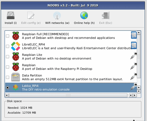
    The NOOBS screen will appear, displaying two installation options: Raspbian Full and LibreELEC. To get further installation options, you will need to be connected to the internet. 

    Connect Raspberry Pi directly to your modem/router using an Ethernet cable; or click the ‘Wifi networks (w)’ icon. The WiFi network selection window appears; wait until it displays the local networks. Select your wireless network and enter the password for it in the Password field. Then click OK.

    With Raspberry Pi connected to a network, you get a much broader range of installation options. Near the bottom will be Lakka_RPi4.

    Use the arrow keys on your keyboard to select Lakka and press the SPACE bar to add a cross to its selection box (or use a connected mouse to select the Lakka option).

    Click Install and answer Yes to the Confirm window. NOOBS will download and extract the Lakka file system to the microSD card. Sit back and wait for the system to be installed.

    When it has finished, NOOBS will display ‘OS(es) Installed Successfully’. Press ENTER on the keyboard (or click OK with the mouse).

    Starting Lakka

    Lakka's main menu. Cores are the emulators used to run retro games. They are modular components based on classic systems and games

    Raspberry Pi will restart and this time it will boot into the Lakka operating system. You will see a blue screen with a series of windows and ‘Load Core’ will be highlighted. You can use the arrow keys on the keyboard to navigate the menu, and X to select a menu option, then Z to back up.

    Highlight Load Core and press X to select it. Here you will find a list of ‘cores’. These are the engines that emulate different retro consoles and computers.

    To test the system is working, highlight 2048 and press X again. You’ll be returned to the main menu, but this time you’ll see ‘Start Core’. Press X to start the core and you’ll be presented with a classic game called 2048. Use the arrow keys to slide the blocks together. Matching numbers double in size, and the aim is to make a 2048 block. Press ESC and ESC again to return to the main Lakka menu.

    Connect to the network

    You need to connect Lakka to the network. Use your cursor keys to navigate Lakka’s menus, and head to the Settings list. Press the down arrow and select ‘Wi-Fi’. Wait for Lakka to scan the local networks.

    Select your wireless LAN network and use the keyboard to enter the Passphrase. The Lakka interface will display the name of your wireless network with ‘Online’ next to it.

    Get a game

    Blade Buster, a homebrew shoot-’em-up, running on a Raspberry Pi 4

    Now it’s time to find and play a game. Games are downloaded as ROM files and added to Lakka. These ROM files need a compatible core to run (most but not all ROM files will run correctly). 

    We’ll use a Japanese homebrew ROM called Blade Buster. Download it on your PC or Mac from magpi.cc/bladebuster – click the ‘Blade Buster Download’ link. 

    A file called BB_20120301.zip will appear in your Downloads folder. Unlike NOOBS, you do not extract the contents of this file – ROMs are run as compressed zip files. You now need to transfer this file from your computer to your Raspberry Pi.

    Turn on Samba

    With your Raspberry Pi and PC on the same network, go to the Settings menu in Lakka on your Raspberry Pi and select Services. Highlight Samba and turn it on by pressing X (or using right arrow).

    Samba is installed by default on macOS and used to be installed by default in Windows, but it has recently become an optional installation.

    In Windows 10, click on the Search bar and type ‘Control Panel’. Click on Control Panel in the search results. Now click ‘Programs’ and ‘Turn Windows features on or off’. Scroll down to find ‘SMB 1.0/CIFS File Sharing Support’ and click the ‘+’ expand icon to reveal its options. Place a check in the box marked ‘SMB 1.0/CIFS Client’. Click OK. This will enable Samba client support on your Windows 10 PC so it can access Raspberry Pi.

    Transfer the ROM

    Lakka may appear in the left-hand column of your other computer’s file browser (File Explorer on a PC or Finder on a Mac). If not, select Lakka’s main menu on your Raspberry Pi, then choose Information and Network Information.

    Take note of the IP address. Enter that into the File Explorer using the format: \\insert.full.ip.address\

    Ours, for example, is: \\192.168.0.13\

    Copy the Blade Buster zipped game to the ROMS folder on Lakka. 

    Back on your Raspberry Pi, go to Load Content > Start Directory in the Lakka menu and find the BB_20120301.zip file. Click it before selecting Load Archive. Choose FCEUmm as the core to play it on.

    Press ENTER to start the game. Use the arrow keys to move and X to fire. Enjoy playing the game. Press ESC twice when you’re done, to return to Lakka.

    Top tip: SSH

    You can also use SSH to copy files from your computer to Raspberry Pi. In Lakka, enable SSH in Services. You can use a program such as FileZilla to copy files across. See magpi.cc/ssh for more information.

    Set up a controller

    If using a wireless gamepad, insert its dongle into one of Raspberry Pi’s USB ports, insert the batteries, and turn it on. Press the Start button on the gamepad and it will light up.

    Video game consoles rarely come with keyboards. And no doubt you’ll want to attach a controller to your console.

    If using a wireless gamepad, insert its dongle into one of Raspberry Pi’s USB ports, insert the batteries, and turn it on. Press the Start button on the gamepad and it will light up.

    Use the arrow keys to choose Input and User 1 Binds. If it is connected correctly, you will see ‘RetroPad’ next to User 1 Device Type. Scroll down and choose User 1 Bind All. Follow the on-screen instructions to press the buttons and move the analogue sticks on the gamepad. You may have to go through it a few times to get the process right.

    You can also set each button individually using the options. Once everything is set up correctly, you’ll be able to use the gamepad to control your Raspberry Pi console.

    Move to the television

    Your Raspberry Pi games console is now ready to be moved to your television. You will be able to control the games console using your USB or wireless controller and move ROM files directly to it from your Windows PC or Mac computer. 

    There’s a lot more to Lakka to discover, but for now we hope you enjoy playing retro games on your Raspberry Pi console. It’s worth heading over the Lakka forums for friendly help and advice: magpi.cc/lakkaforum

    Lakka controls: match the buttons and sticks on a gamepad to the controls used in each core

  • Learn computing systems with Raspberry Pi

    Learn computing systems with Raspberry Pi

    Reading Time: 3 minutes

    The Elements of Computing Systems is the book behind the more popular Nand to Tetris course

    By Noam Nisan and Shimon Shocken

    • Price: £25/$35

    Modern computing systems are built on a stack of technologies. Right at the top, you have the operating system and high-level languages like Python. These sit above a virtual machine that communicates via assembly language to the hardware, which itself is built on a system of chips and logic gates. Head down and you’ll hit physics.

    Professional programmers often don’t know what’s going on deep down in the computer system. They rely on the fact that what they do works. 

    The Elements of Computing Systems is the book behind the more popular Nand to Tetris course (aka ‘nand2tetris’).  Using a hardware simulator to build a NAND (NOT-AND) gate, the latter is then used to build all the other chips and gates that form a computer. You then use that to build a general-purpose computer system, called Hack; and a compiler, called Jack. You use these to build an operating system.

    The corresponding website (nand2tetris.org) has projects, software installation, and sample programs made with Jack (including the aforementioned Tetris). 

    By David Wentzlaff

    • Price: free

    Princeton University’s Computer Architecture course is on Coursera and is widely regarded as one of the best ‘all-rounders’. The course covers architecture, pipelining, cache, superscalar, and works its way up to multiprocessors. 

    The course is led by David Wentzlaff, Associate Professor, Electrical Engineering at Princeton, and he leads you through the concepts. By the end of the course, you will have a good understanding of the different types of processor architectures.

    You can enrol on the course for free, although there is no certificate for completion. 

    David Wentzlaff's Computer Architecture course is widely regarded as one of the best ‘all-rounders’

    By Parrot

    • Price: £100 / $130

    Computer Organization starts with computer and performance, before moving on to processor unit design and memory system design, then input-output design and pipeline design techniques.

    Of particular interest for Raspberry Pi fans is its coverage of RISC – reduced instruction set computers. It’s developed using the GATE (Graduate Aptitude Test in Engineering) syllabus, making it useful for undergraduates. But the course content of use to anybody interested in learning computing architecture.

    The price is listed at $132, but it’s frequently on sale (it was $10 at the time we went to press, so look out for that). 

    Computer Organization teaches you about Raspberry Pi and RISC but is also of use to anybody interested in learning computing architecture

    More computing books you need

    Code: The Hidden Language of Computer Hardware and Software 

    This book is famous for explaining complex concepts to non-technical people. It doesn’t teach anything about programming, but is a great place for absolute beginners.

    The Hidden Language of Computer Hardware is a great place for absolute beginners

    But How Do It Know? 

    This book is designed to bridge the gap between knowing the major parts of a computer and starting a complete course. The first three chapters are available on Google Books (magpi.cc/tQrtY5).

    Algorithms to Live By

    Learn how computer science can be applied in the real world (and gain a further appreciation for the computing concepts in the meantime).

    Websites are also excellent resources for learning about computing. The GeeksforGeeks website should be bookmarked anyway, but take a look at the Computer Organization and Architecture tutorials section.

    Stack Exchange has two useful boards for you: Computer Science and Electrical Engineering. Sign up with both.

    There are countless CPU simulation programs and sites to explore, many based on the Little Man Computer model. Why not start with this offering?

    The GeeksforGeeks website is well worth bookmarking

  • Interview with Liz Clark aka Blitz City DIY

    Interview with Liz Clark aka Blitz City DIY

    Reading Time: 4 minutes

    Not everyone has been tinkering with electronics for decades. Some are new to the hobby, and it’s easy to figure out why: information on the internet is easier to obtain than ever, and the low cost of Raspberry Pi has helped to further its accessibility. Liz Clark is one of those newcomers. She’s a Vlogger and community YouTube channel owner.

    Liz Clark, vlogger and owner of community YouTube channel Blitz City DIY

    “I actually got a bit of a ‘late’ start to making (although I’m a firm believer that it’s never too late to learn something new),” Liz tells us – and we completely agree.

    “I was in college and decided that I should try and learn some coding without really knowing what that meant. I was majoring in music technology, so I began my search in the music arena and learned about Arduino and all of the MIDI projects that people were beginning to make with them. I dabbled a bit off and on with it, but it wasn’t until about four years ago that I really got serious about it and now I’m doing a bit of everything: CircuitPython, 3D printing and design, PCB design, and of course a hearty portion of Raspberry Pi. Outside of hardware, though, I am a long-time avid knitter, cross-stitcher, and sewer.”

    We’d also argue that textile arts are a form of making as well, just a bit more low-tech.

    Why did you start your channel?

    Related to my ‘late’ start in making, I had been out of college for about two years and was starting to feel a little stuck. I really wasn’t working on any creative projects and I was worried that I was going to permanently fall into that rut working full-time. I also have a video background and I hadn’t filmed and edited anything for fun at that point since school, so my channel was basically born from a place of worry and/or quarter-life crisis.

    Setting up my YouTube channel Blitz City DIY was a very surreal and odd thing for me to do because I definitely lean more toward the introverted side, so the idea of me talking on camera about things was completely outside of my comfort zone. However, I’ve become a lot better at speaking as a result, and my goal for working on creative projects and keeping up my video skills wouldn’t have been possible without my channel. It’s also led to some really amazing opportunities that otherwise I wouldn’t have had, so I’m so glad I took the initial risk.

    When did you first learn about Raspberry Pi?

    I first learned about Raspberry Pi a couple of years ago, around the time that I was starting my channel. It honestly seemed a little mysterious to me at first because I wasn’t quite sure what it was or what it did, but I quickly fixed that and fell in love with Linux and all things single-board computers.

    Adafruit's AMG8833 thermal camera and Pi Bonnet which Liz housed in a modified picture frame then routed to Raspberry Pi's GPIO

    Blitz City DIY Raspberry Pi projects

    “I rigged up a thermal camera using the AMG8833 thermal camera module from Adafruit. It was before I had a 3D printer, so the housing was in a modified picture frame. That project also ended up becoming my first PCB – I designed up a quick Bonnet-type board to just easily route the thermal camera module to Raspberry Pi’s GPIO.

    Raspberry Pi NoIR Camera Module isn’t the only IR camera for Raspberry Pi – Adafruit also has the AMG8833 Grideye

    “I also have an OpenMediaVault instance running on a Raspberry Pi that I use as a home media server and network backup for my computers, and I do run Steam Link on a Raspberry Pi as well. I think that’s one really cool thing about Raspberry Pi in general: you can run a lot of different types of projects on them and there’s always more flavours of Linux becoming available for them too.”

    A familiar sight to many Raspberry Pi owners – a Raspberry Pi-powered media server. We like the 3D-printed mounting to cut down on the footprint

    Any future Raspberry Pi plans?

    I’m actually working on a big Raspberry Pi project right now. It’s going to be a MIDI-powered robot xylophone. I’m using tiny solenoid motors to strike the keys on a glockenspiel and I’m using MIDI-in over UART (Universal Asynchronous Receiver/Transmitter) on Raspberry Pi. I also made a custom HAT PCB to connect up the MIDI-in circuit and multiplexers to Raspberry Pi’s GPIO. It’s definitely a concept that’s been done before, but having a music background and being a former mallet player, I’m really excited to create my own version.  

    Liz is working on a Raspberry Pi robot MIDI xylophone

    More inspiring Raspberry Pi makers

    Read about more music-based Raspberry Pi makes such as the Perpetual Chimes project, discover some very impressive art project makes and, if you’ve set up your Raspberry Pi as a media server, learn which media player will make the most of your audio collection.

  • Make your own smart Christmas tree lights

    Make your own smart Christmas tree lights

    Reading Time: 6 minutes

    Christmas is here, and that means it’s time to decorate. Over the years, we’ve made Christmas tree stars, normal tree lights, and even a light-up card you can make out of the cover of The MagPi issue 52.

    This year, we’re heading back to the tree lights to give them an extra ability: voice-controlled lights! We’ll be doing this using a slightly easier method than other audio services, so you won’t need to sign up to an Amazon or Google developer account. Let’s get festive!

    You’ll need

    The right lights

    For our specific build, we’re using 3m of RGB NeoPixels with 30 LEDs per metre. You can find the ones we used here: magpi.cc/iP97nc. These may not be the right lights for you, though. While we think 144 lights per metre is a bit much, the 60 lights per metre version would work well wrapped around a tree or installed on some other furniture. You may also consider getting RGBW LEDs for a brighter (and easier to program) white light effect if you desire.

    Install the software

    For the voice control and NeoPixels, we need to install a few extra Python libraries to Raspbian. First, install SpeechRecognition by opening the Terminal and typing:

    sudo pip3 install SpeechRecognition

    Then we need to install PyAudio and a FLAC encoder so that Raspberry Pi can hear what you’re saying and record it. Do it with:
    sudo pip3 install pyaudio
    sudo apt install flac

    Plug in a microphone and make sure Raspbian is using it as an input device (you may need to right-click on the volume icon in the top right to do so). Then run the test script:

    python3 -m speech_recognition

    It will ask you to speak a word and it should return what you said.
    Finally, install the NeoPixel libraries with:

    sudo pip3 install rpi_ws281x adafruit‑circuitpython-neopixel

    Top tip: speech-recognition troubleshooting

    If you’re having trouble with the test for the SpeechRecognition library, head here to troubleshoot: magpi.cc/RgpLyc.

    Build the circuit

    Build the circuit using the Fritzing diagram as a guide (Figure 1, overleaf). A Raspberry Pi can only power a handful of NeoPixel LEDs safely at a time, which is why you need an external power supply to power the LED strip. Four rechargeable AA batteries will get you the roughly 5 V you need. However, if you have a spare 5 V power supply and a jack to use, that will work just as well, if not better.

    The button is installed so we can activate the voice commands – it’s much easier than adding a trigger word like on a home voice assistant.

    The smart lights circuit is fairly simple – make sure you connect the DIN side of the NeoPixels to your Raspberry Pi

    Test your lights

    Once the circuit is all wired up, test your NeoPixels using the neopixel_rpi_simpletest.py script (if you can’t find it on your Raspberry Pi, head here: magpi.cc/Pci4iN).

    Change the number of NeoPixels to your requirements and run the script. If the colours seem off, you may need to change the ORDER = line from neopixel.GRB to neopixel.RGB – or neopixel.GRBW or neopixel.RGBW if you have an RGBW strip of NeoPixels.

    This is also a good chance to make sure your circuit is properly wired up – check the grounds, the specific GPIO pins used, and whether or not it’s powered properly.

     Test your NeoPixels light setup while you’re building, so you can discover any issues early on

    Tweak the code

    Download or type out the code listing for this tutorial – smartlights.py. This code was specifically tailored to our build, so you may need to make some changes to the code: specifically, the number of NeoPixels in your circuits, the type of NeoPixels (RGB/GRB/RGBW/GRBW), and the GPIO pins you’re using for the lights and button if you modified our circuit.

    Save the file, open up the Terminal, and enter:

    sudo nano /etc/profile

    Add this line to the end of the file:

    sudo python3 /home/pi/smartlights.py &&

    This will start the script automatically whenever you turn on your Raspberry Pi.

    Explaining speech recognition

    The speech recognition part of the code is remarkably simple, and is mostly handled by the speech recognition library. It’s imported as sr in the script, and we use it to listen in on the microphone when required. Once a phrase has been said, it sends an audio file to Google Speech Recognition to be analysed, which is the value variable in our code.

    We use this value variable to check against our if statements – you’ll notice we haven’t capitalised ‘lights on’ or ‘lights off’, but we have done for ‘Merry Christmas’ as it returns the value in that way. If you plan to add more phrases, you may need to experiment with them.

    Adding trigger phrases

    We’ve tried to keep this very simple, including trigger words as part of if statements. To add one, all you need to do is add an extra if statement to the loop. Say you want to add the term ‘happy holidays’, you’d do so like this:

    if value == ‚happy holidays‘: strip.fill((255,0,0) strip.show()

    In this example, we make the lights turn bright red.

    Custom light patterns

    The basics of setting LED colours with NeoPixels involves telling the NeoPixels which red, green, and blue (RGB) values to use, from 0 (off) to 255 (maximum). In the previous step, we set red/R to 255 for full red. You can make all three 255 for white. Check out this colour chart to find colour values.

    For more complex lights (alternating colours, rainbow effects, etc.) you’ll need to create a specific function that executes the effect. Some of these can be quite complicated, so we suggest checking the examples and docs for the NeoPixel library if you have an idea you’d like to try.

    Top tip: RGBW code

    With RGB NeoPixels, you only need to program three variables: red, green, and blue. With RGBW ones, you’ll need to add a fourth, e.g. (255,0,255,255).

    Install your lights

    Once you’ve perfected your lights and voice control, it’s time to put the lights up! We like to wrap ours around the tree, making sure there’s easy access to change any batteries. You may need to add some clips to the tree as well.

    If you plan to stick them to other furniture, you may need to make sure you have a temporary solution, like Velcro with sticky backs, so you can easily add and remove them at the start and end of the festive season.

    Light up your tree!

    It’s time to do the final test of your lights and turn them on! Test out the voice control, and maybe think of moving the microphone position around. With some really long wires, you can also put the button to activate the speech recognition in a place that’s easy to reach.
    At the end of the day, you don’t have to turn the lights off, either: you just need to say ‘lights off’.

    Adding sound and more

    One extra feature you might consider is sound output, which can be handled with Pygame. For some voice keywords, you could have lights sync up to classic Christmas songs, carols, or whatever you choose.

    We suggest making it so the song only plays through once before going back to normal, though, to avoid incurring the wrath of the people you live with. Last year we create a tree-topper star – you can easily add some NeoPixels to a 3D-printed star like this and have the system control it as well!

    Happy Holidays!

    We really hope you enjoy making this project and, even if you don’t celebrate Christmas, we hope you think of it as a great introduction to voice control with Python.
    From all of us at The MagPi, Happy Holidays and a Happy New Year!

    PS: don’t forget to share your cool Christmas makes with us on Twitter or Facebook. We might even feature them in The MagPi!

    What else could you do with Raspberry Pi-controlled lights? How about a multi-coloured bookshelf light display?

    Looking for more projects for the festive season?

    How about a GPIO Christmas Tree? Make a Harry Potter fan very happy with this Magic Wand that really makes things move. Entertain the family with this Python-based quiz.
    Impress them with this unexpected party popper launcher and by serving up festive cocktails courtesy of your Raspberry Pi butler.