Kategorie: Reviews

  • POV Display

    POV Display

    Reading Time: 3 minutes

    By rotating a strip of LEDs at high speed and syncing their blinking patterns, it’s possible to create the illusion of a still or moving image. This is just what Japan-based family team of makers HomeMadeGarbage have done for their POV Display, even spinning a Raspberry Pi Pico around with the LED strips.

    Power of PIO

    The makers tell us that, after creating a similar project using Sony’s considerably more expensive Spresense board, they were inspired to try it with Pico, as they were “very surprised at the parallel high-speed operation of PIO.” The latter is the unique Programmable Input/Output feature of Pico’s RP2040 chip that enables the use of custom communication protocols in addition to the built-in I2C and SPI. This offers a faster way of outputting bit-banged data (even video) to non-standard devices with a deeper level of control, without tying up the main processor.

    Mounted on the other end of the rotating arm, Raspberry Pi Pico controls the LEDs

    The POV Display uses two different PIO state machines (from the eight available on the chip) to control, in parallel, a pair of super-bright 24-LED APA102 (aka DotStar) strips on its rotating arm. The arm is spun at high speed by a Mabuchi RS-540SH motor, as commonly used in remote-control cars.

    Each rotation is detected using a reflectance sensor on the arm and a small white marker underneath. HomeMadeGarbage say that they improved detection reliability by inserting “a filter and a Schmitt trigger between the reflectance sensor and Pico to prevent chattering.”

     When the arm is spun rapidly, the LEDs are blinked rapidly in a pattern

    In the software, written in C, the time taken for one rotation is divided by 1000 to sync the blinking of LED patterns stored in a graphics array. “In order to leave a beautiful afterimage, a speed of ten revolutions or more per second is required,” reveal HomeMadeGarbage. 

    Discovering that “the I/O of Raspberry Pi Pico can run very fast”, they’ve managed to spin the arm at up to 960rpm while displaying an image at 1000 frames per rotation.

    Spinning around

    With everything, including Raspberry Pi Pico, whizzing around at high speed, you may well be wondering how it’s powered without quickly causing a tangle of wires. The solution is the use of a wireless charging module, one of whose circular coils sits on top of the motor, the other in the underside of the arm centre. “5V is supplied to the transmitting side of the wireless charging module, and the receiving side receives the voltage, [which] drives Pico, sensor, and LEDs.”

    After posting a video of the POV Display in action, HomeMadeGarbage found that people were “surprised at the high-speed operation.” They now plan to make an improved version with a narrower-pitch LED bar. Also on the cards is a 3D POV Display using Pico – we can’t wait to see that!

  • Automated camera-based drone landing system

    Automated camera-based drone landing system

    Reading Time: 3 minutes

    To do this, Chinthaka has been leading a team in using a standard radio-controlled quadrocopter drone fitted with a Raspberry Pi 3B+  and a Camera Module. They’ve worked on an automatic landing system, allowing the drone to be brought down to the ground without mishap.

    “Automatic landing is a kind of automatic flight towards a specific landing spot and to achieve this with a drone it must find the landing spot itself,” Chinthaka explains. “I believe that landing spots can be recognised by processing the images from an on-drone camera, but this image processing needs to be implemented in real-time, generally less than 15 milliseconds.”

    Be snappy

    It’s this need for fast on-board processing that led Chinthaka to consider using Raspberry Pi. “The idea is that flight control is conducted as soon as the images are processed, so we not only needed a good, lightweight camera but a lightweight on-drone computer too,” he reveals. “Raspberry Pi 3B+ is obviously lightweight and it can be easily implemented within a drone. Raspberry Pi 4 can be used for this too.”

    The drone looks for the landing pad by monitoring captured images before moving to the landing spot, hovering, and determining that it’s safe to land

    The camera was chosen because it has a wide angle. “It’s wider than the other cameras that are compatible with Raspberry Pi, so it can capture a large area and this capturing ability makes it easy to identify a landing spot,” says Chinthaka. A depth camera was also important. “During the drone landing, the ground object information can be easily recognised with a depth camera rather than a 2D camera.”

    For optimal results, the camera lens is kept horizontal, even when the drone body is not in this position during the flight. “If the lens was not always horizontal, then it would be difficult to smoothly capture the landing spot during flight because of the shaking of the drone,” Chinthaka says. “We made our own lightweight gimbal to keep the camera lens horizontal but a commercially available gimbal may also be used for this task.”

    H marks the spot

    The idea is that the drone looks out for an H-shaped symbol placed on the ground at the landing location. Using software created by the team, the image is processed and converted into physical co-ordinates to generate a horizontal feedback.

    The wide-angle camera can capture a large area to help identify a landing spot

    “Some parts of the software include OpenCV library functions,” says Chinthaka. “We also wrote software for the landing process, but developing the necessary algorithms to detect the landing spot in real-time was the greatest challenge.”

    Even so, the researchers were able to get the image processing time down to three milliseconds. This allows the drone to quickly fly over to the landing spot, hover over it and land vertically, all controlled by Raspberry Pi. “It’s been a big success and we expect it will have a wide number of future uses,” Chinthaka concludes.

  • Interview: Kevin Johnson

    Interview: Kevin Johnson

    Reading Time: 3 minutes

    “So my official title is Club Programs Coordinator,” Kevin tells us. “What that means is I help develop engagement strategies and also implement them to keep our youth programs community (Code Club, CoderDojo, Coolest Projects) in the USA fully immersed in all of the free resources we have. It involves a lot of writing, which I love because my background is in creative writing, so I write monthly newsletters and blogs, I design seasonal competitions for young people to participate in, I try to maintain our presence on social media, and a bunch of other things. I’m truly a wearer of many hats!”

    What did you know about Raspberry Pi before joining?

    Full transparency, I did not know much about Raspberry Pi prior to joining the Foundation because my introduction to tech was mainly focused in Adobe Creative Suite programs like Photoshop, Illustrator, Premier Pro, etc. I was in a multimedia academy (CMMA) in high school, so I dabbled a little bit with coding, but not enough to know about the different hardware out there. My knowledge of Raspberry Pi came when I discovered the job listing and after reading through the Code Club and CoderDojo blogs, I was immediately hooked. To see such a small device have such a large impact on people all over the world, especially people from different socioeconomic backgrounds, I had to have the job. Fast-forward two years and here I am, still loving every minute!

    You’ll see Kevin helping out at just about every event in the US, and some elsewhere in the world!

    What are some of your favourite moments with the Raspberry Pi community?

    I had a blast co-hosting last year’s Coolest Projects USA event that we held in Santa Ana, CA at the Discovery Cube Orange County! I love the energy that young people bring to any space and in that space the energy was at an all-time high. Also, who hasn’t dreamed of being a talk show host?! If you can get on a stage and keep a group of young people entertained and laughing, it’s a great sign that you’re doing alright in life. I have to also mention the few trips our team here in the USA have taken to Cambridge to visit the Foundation headquarters; those have been some of the greatest moments of my life! Being part of a global community, learning about other cultures, connecting with colleagues on a more personal level is just amazing. It means the world to me to work for a global organisation that finds importance in bringing its employees together not just to work, but to also play and have fun.

    Coolest Projects USA is a huge event which Kevin not only co-hosted, but he was also one of the organisers

    What can you tell us about upcoming events?

    We’re really excited about this year’s Coolest Projects event, especially because this will be a global event where we will hold one event for all of our participating regions. Here in the USA, we were lucky to be able to have the event in-person right before the lockdowns started last year, so while we did get to experience that, we did not get to experience the event online like everyone else. Collaborating with the global team on the upcoming Coolest Projects Online has birthed some really awesome ideas that we can’t wait to share with everyone come early June when this year’s showcase happens!

  • Review: IoT Cricket

    Review: IoT Cricket

    Reading Time: 3 minutes

    The IoT Cricket (£16) is a small package based on the ubiquitous ESP8266 chipset, popular for its solid wireless LAN support. ESP microcontrollers are widely available and some can be had for just a couple of pounds, so it may come as a surprise to see a British-designed and made product introduced to an already saturated market. Turns out there are a few things that make this device different from the rest.

    The IoT Cricket is small, elegant, and perfect for single-purpose use

    The IoT Cricket appears to have been designed around the philosophy of ‘do one thing and do it well’. At first glance it may not seem like a good deal. It’s more expensive than many similar controllers and lacks a full range of inputs as seen on Arduino-compatible ESP devices. In fact, the IoT Cricket boasts a total of one digital and one analogue input and a 3.3V output. This simplistic approach and some clever design solves one of the great headaches of ESP-based IoT devices: power. By combining a real-time clock into the design to control wake-ups as well as a ‘wake up’ line, it draws true 0A when idle. It can also operate on voltages from 1V up to 3.3V. This means you can power it from a single AAA battery for potentially months, even years, depending on activity.

    Zero-code configuration

    You can’t write code for the IoT Cricket. Everything is configured using an on-board web interface (there is also an over-the-air solution). Placing it into configuration mode (using the smallest button we’ve ever seen) starts a wireless hot spot that allows you to set the behaviour of the device. Options include using the RTC to wake the device at given intervals, how to read inputs, and also what to do with the data. IoT Crickets support MQTT and HTTP GET or POST actions, making them instantly compatible with a huge range of monitoring and alerting services. Things On Edge even provides a free MQTT broker if you don’t want to set up your own.

    You can configure the IoT Cricket through its web interface, even remotely using its OTA feature

    Programming microcontrollers is not for everyone (especially if you’re using C), so this novel approach of configuring the IoT Cricket places the Internet of Things within the reach of a much wider audience. Even if you are accustomed to coding ESP devices, getting a simple project up and running with this approach is much quicker.

    Things On Edge has provided several examples of projects using the IoT Cricket, including door sensors, wireless light controllers, motion detection, and more. There is also considerable documentation on integrating with services such as IFTTT and Home Assistant. They’ve even included an on-board temperature sensor (TMP1075DSG) so you can get started with no soldering. The online documentation can be a little hard to wade through, but seems to be constantly improving. All-in-all, it’s a very impressive device if you want ultra-low power consumption and very easy setup.

  • Autonomous Home Robot

    Autonomous Home Robot

    Reading Time: 3 minutes

    “I have always loved robots,” Nick tells us. “Building my own autonomous robot has been a goal for me, as long as I can remember. I also wanted to make my robot useful. I am always making things but then end up taking them apart the next week because they didn’t end up being useful. I challenged myself to make this robot useful, and help carry out tasks around the house.”

    And so, several years ago, work on the Autonomous Home Robot began and it’s fair to say that the project has evolved over that time. “It started as a tiny remote-controlled self-balancing robot,” says Nick. “Now it is a big robot that navigates around the house!”

    Nuts and bolts

    Nick’s robot basically consists of two sections: the base and the head. “The base consists of a lidar laser scanner, Raspberry Pi, and Teensy,” he reveals. “The lidar scanner, which is mounted on a small auto-levelling platform, sends its range data to Raspberry Pi. The [latter] is the brain which takes in the lidar data and streams it over to a master computer for processing. Raspberry Pi also sends drive drive messages to the Teensy, which handles motor control.” 

     The lidar sensor is mounted on an auto-levelling platform to counter the tilt of the robot on the floor – this will really come into play when Nick makes the robot self-balancing

    In the head of the robot, Nick has positioned a second Raspberry Pi, an Arduino, and a camera. “Similarly to the base, Raspberry Pi streams the camera feed over to the master computer, and sends head movement commands to the Arduino,” he says.

    The robot navigates its way around the house by using various systems that Nick has installed, and it knows where it is in a room by using wheel rotations (odometry). Nick elaborates, “This odometry is then combined with the laser data to make a map. On the map, I can specify a point that the robot will drive to, and the robot will make its way there, while avoiding obstacles.”

    Robot research

    There was a great deal of technical coding, along with languages and systems, to learn before Nick’s robot came into being, including Python, C, HTML, and OpenCV. The hardest part was to learn Robot Operating System (ROS). “It took a lot of reading and studying to set up the robot. Once I was motivated enough to put in the time to really learn ROS, everything fell into place.”

    On the lower part of the robot is a 12V 10A power system for the motors. A 5V 16A USB power brick is used for the two Raspberry Pi boards

    Nick is the first to admit that his robot is an ongoing project and is continually evolving, but the potential is there for it to perhaps carry things around the home, act as a robotic companion, and more. He’s already made many finely tuned modifications.:“I have added many things to the initial design, like tilting laser scanners, tilting cameras, a rotating head, and even the temporary four-wheel drive base.”

    He also has plans for a lot more improvements, “including new motors, making the robot self-balancing, Raspberry Pi 4s, and a big battery so that the robot can completely navigate on its own.”

    Nick is clearly very self-motivated and has input many hours of hard work to get to this point. “I asked for feedback recently from my engineer friend who encouraged me to focus on getting the core of the robot working well and stop adding extraneous features. A combination of his help, along with many others, have helped make this robot work!”

  • Build the home of the future in The MagPi #104

    Build the home of the future in The MagPi #104

    Reading Time: 3 minutes

    Home of the future

    Home of the future 

    This is a wonderful feature that’s packed with innovative ideas for DIY projects. We’ve gone room-by-room around the house and looked for Raspberry Pi projects that turn a dull house into a smart home.

    Pico-died Raspberry Pi projects

    Pico-fied Raspberry Pi projects

    Raspberry Pi’s new microcontroller offers new ways to go about classic builds. In this feature, we look at the ways makers are using Pico to reimagine their Raspberry Pi projects. From motor controllers to music and MIDI generation. 

    iPod Classic Spotify player

    iPod Classic Spotify player

    The iPod Classic was great for its time. But the world has moved on to music streaming. What better way to rediscover this old piece of kit than to use Raspberry Pi Zero to add Spotify to it? We take a look at this wonderful build.

    Kay-Berlin Food Computer

    Growing food with Raspberry Pi: Kay-Berlin Food Computer

    Automated farming may be the future for the agriculture industry. Some makers are using Raspberry Pi to experiment with growing food automatically. The Kay-Berlin Food Computer is a fully automated growth chamber that can monitor over a dozen atmospheric and root zone variables. Tasty!

    Build an arcade machine: Get the parts

    Build an arcade machine: Part one, get the parts

    Many makers dream of owning an arcade machine. This month, KG Orphanides is starting a new series on building an arcade cabinet from scratch. We’ll look at the parts you need to buy, and a few places to get them from. Join us on a journey to own our very own coin-op classic. 

    Cheap trills for all: MIDI guitar

    Make a MIDI guitar with trill sensors

    Mike Cook has been busy with Trill sensors in the last few issues of The MagPi magazine, and this issue he gets to use them with Raspberry Pi Pico to build this rather cool MIDI guitar. It reminds us of the Guitar Hero video game (but it’s much more versatile).

    Pico Explorer Base

    Prototype electronics with Pico Explorer Base

    Raspberry Pi Pico is a wonderful piece of kit, and the only thing that makes us more excited is the wide range of products coming out. One of the first off the blocks is Pimoroni’s Pico Explorer Base. Experiment with electronics, and a mini display, and build your own Pico physical computing projects.

    Pick up your copy of The MagPi magazine #104

    The MagPi magazine is available as a free digital download, or you can purchase a print edition from our Raspberry Pi Press store.

  • Win one of six SmartiPi Touch Pro Cases!

    Win one of six SmartiPi Touch Pro Cases!

    Reading Time: < 1 minute

    Subscribe

  • Make a digital do-not-disturb sign

    Make a digital do-not-disturb sign

    Reading Time: 6 minutes

    In this tutorial we’re going to use a popular messaging protocol, MQTT (Message Queuing Telemetry Transport). With MQTT we will set up a simple do-not-disturb sign that you can trigger with a single key press and customise to your heart’s content.

    Step 01: Prepare Raspberry Pi

    We’re using two Raspberry Pi Zero W computers for this project, although it will work with any recent model. For both, we recommend installing Raspberry Pi OS Lite (magpi.cc/software) as we don’t need a desktop interface. Make sure both devices are working and connected to the same network. We also recommend setting their host names by running sudo raspi-config at the command line, then going to System Options > Hostname. We chose ‘busybot’ for the sign and ‘buttonbot’ for the controller and that’s how we’ll refer to them throughout this tutorial. Finally, make sure everything is up-to-date. Enter these commands:

    sudo apt update
    sudo apt full-upgrade

    You should be able to ping one device from the other. On ‘busybot’ Raspberry Pi Zero W, enter:

    ping buttonbot.local

    You should should get a response from ‘buttonbot’ Raspberry Pi Zero W.

    Step 02: Install the Scroll pHAT HD and diffuser

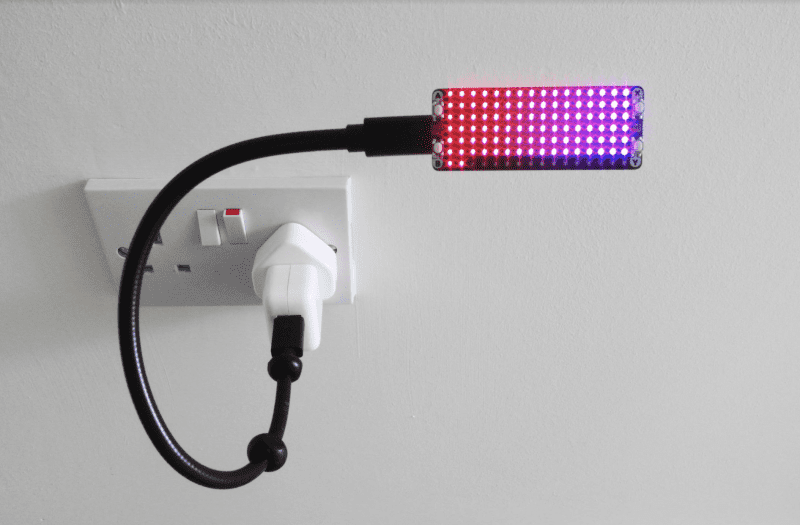
    We’re going to set up the display first. Pimoroni’s Scroll pHAT HD is a display made up of 17×7 pixels (119 total) and comes with a Python library that does all the hard work of displaying and scrolling text for us. The pHAT form factor makes it just the right size for a display, but of course you can adopt this tutorial to any display you like. You’ll need to solder the 40-pin header to the display and also add a reciprocal header to ‘busybot’ Raspberry Pi if it doesn’t already have one. Before assembling them together, screw on the diffuser, which will make the display much easier to read. Now, with Raspberry Pi powered off, carefully connect the Scroll pHAT HD.

    Step 03: Set up the display software

    It’s time to make sure our display is working before we go any further. Fortunately, Pimoroni has created an install script for us. At the command line, run the following:

    curl https://get.pimoroni.com/scrollphathd | bash

    Make sure you do the ‘Full Install’ when the option is presented. This will set up Raspberry Pi so it can communicate with the display and install all the Python libraries we need. Take a look at Pimoroni’s GitHub (magpi.cc/scrollphatgit) for more information on installation.

    Once the install has finished, we can test things out. Reboot, then try this on the command line:

    cd ~/Pimoroni/scrollphathd/examples
    python3 swirl.py

    See a pretty pattern? Then you’re ready to proceed. Have fun with the other examples in the directory; they’re a great source of inspiration.

    Step 04: Introducing MQTT

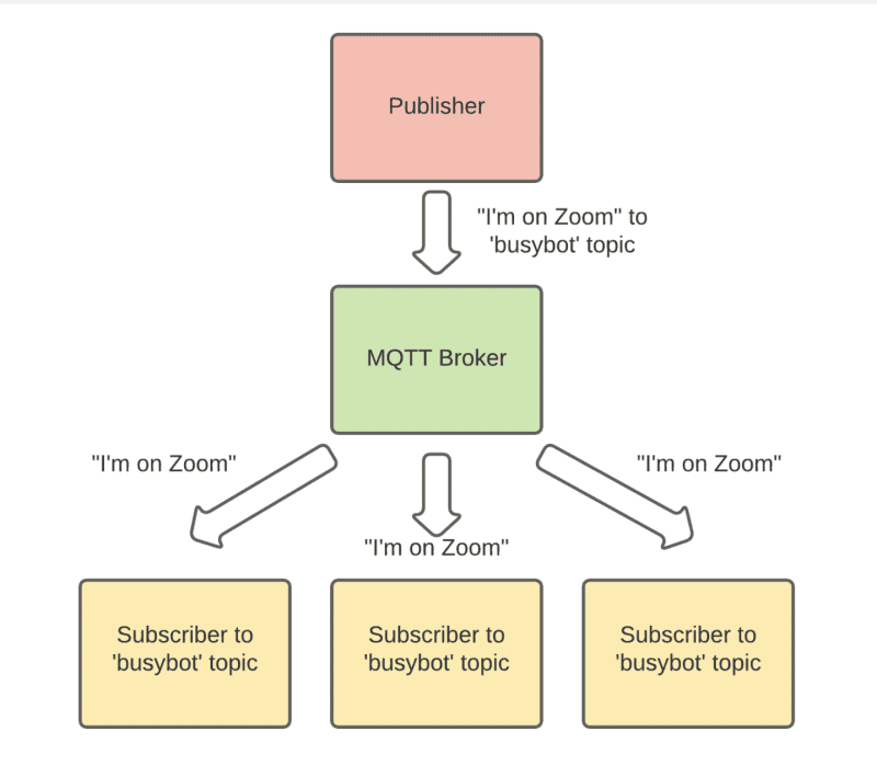
    Our buttonbot and busybot are going to need to talk to each other over the network. One of the easiest, and most popular, ways to do this is the MQTT protocol. It uses a pub/sub model (publisher / subscriber) to process messages. An MQTT server (the ‘broker’) receives messages from ‘publishers’ that are then transmitted to ‘subscribers’. These are organised by ‘topic’. The biggest advantage is that publishers don’t need to understand or even be aware of the subscribers, they just need to speak MQTT. Don’t worry if this is confusing; working through the tutorial will make things clearer.

    Step 05: Mosquitto

    For our system to work, you need an MQTT server (or ‘broker’) to handle the messages. This can be anywhere on your network, but for the purposes of the tutorial we’ll install it on the same ‘busybot’ Raspberry Pi driving the display. MQTT software tends to be very ‘lightweight’, so a Raspberry Pi Zero W can easily handle being the server as well as a publisher. Mosquitto is probably the most popular set of MQTT tools. Installation is straightforward, too. Enter this at the command line:

    sudo apt install mosquitto mosquitto-clients
    sudo pip3 install paho-mqtt

    The broker will be automatically installed as a service and always be running in the background. We’ve also installed Paho, a popular Python library for implementing MQTT.

    The MQTT protocol is perfect for Internet of Things projects

    Step 06: Busybot’s code

    The code for this project does two main jobs: listens to the MQTT server for new messages, and then takes those messages and scrolls them on the display. You can enter the code shown here or get the files from magpi.cc/busybotgit. We need the code to be running all the time. To do this, create a new file from the command line:

    sudo nano /usr/lib/systemd/busybot.service

    Enter the code from busybot.service. (Change the paths if you’ve created the code elsewhere.) Save the file (CTRL+X and then Y), then enter these commands:

    sudo systemctl enable /usr/lib/systemd/busybot.service
    sudo systemctl start busybot

    Step 07: Testing time

    Let’s confirm that the code is working. Using the Paho MQTT libraries, the code subscribes to the MQTT topic ‘busybot’ on the broker. Whenever anything publishes a line of text to that topic, busybot will be notified, the text delivered and then displayed. We can check everything is working using the Mosquitto command line publishing tool:

    mosquitto_pub -h localhost -t busybot -m "Hello from MagPi"

    If you see the messages scrolling across, then everything is working. Send any message you wish, or a blank space to clear the display.

    The Scroll pHAT HD without its diffuser. 119 very bright LEDs

    Step 08: Assemble the Keybow

    Now we have our display working, it’s time to turn our attention to sending the messages. MQTT is widely supported and you can get clients for almost every platform and programming language in common use. That means we can send messages to the display from pretty much anywhere. In this tutorial, we’re going to use Pimoroni’s Keybow interface to provide a quick way of setting messages. On the second ‘buttonbot’ Raspberry Pi WH, assemble the Keybow as instructed  at magpi.cc/assemblekeybowmini, but don’t install Keybow OS – we’re sticking with Raspberry Pi OS Lite.

    Step 09: Keybow setup

    We’ll now add some code to send messages to the MQTT broker when buttons are pressed. First, from the command line, we need to install some dependencies on buttonbot:

    sudo apt install python3-pip git
    sudo pip3 install keybow paho-mqtt

    Now get the code from GitHub:

    cd
    git clone https://github.com/mrpjevans/busybot.git

    We can now test the Keybow with a simple example:

    cd ~/busybot
    python3 test_keybow.py

    Press the keys. Do they all light up? Then all is well.

    Need more buttons? Try the nine-key Keybow

    Step 10: Keybow code

    In the busybot directory, have a look at buttonbot.py. You’ll also need to change the name of the MQTT broker and/or topic if you’ve used something different. 

    We need to make sure the code is always running, just like busybot. Again, we’ll create a service to do this. From buttonbot’s command line, go through the process in Step 6 to create a service file and enable it. Just make sure you change the

    ExecStart

    line to:

    ExecStart=/usr/bin/python3 /home/pi/busybot/buttonbot.py

    Save the file and enable it as before.

    Step 11: Testing and tinkering

    Everything should now be ready. With both Raspberry Pi Zero computers running, try pressing a key on the Keybow. A message will now scroll across the display on the other Raspberry Pi Zero. Make sure all three keys work. You’re now ready to start customising the system to your own needs. If you edit buttonbot.py, you’ll see some documented options for changing the messages and the colours of the keys. Free free to experiment, make changes and make this code your own. If you need more than three messages, see if you can alter the code to support key press combinations, which would give you up to seven options.

    Step 12: Python vs C++

    As the display doesn’t ‘know’ about buttonbot’s existence, it means that anything capable of speaking MQTT can send messages to busybot to set the scrolling text. It could be done from the command line or when a certain event happens. If you’ve been following the Home Assistant (HA) series in The MagPi magazine, then you may be interested to know that HA speaks MQTT, so the display could be tied to a temperature or motion sensor. Have fun dreaming up new ideas for your display.

  • Build a Pico Pomodoro timer

    Build a Pico Pomodoro timer

    Reading Time: 6 minutes

    But pairing a Raspberry Pi Pico with the bright LEDs of a Unicorn Pack means you can see at a glance when your next break is approaching and, if you keep it just out of your eyeline, that warm red glow is a reminder to carry on working.

    Step 01: Give your Pico some pins

    We want to attach Pico to a hardware array of LEDs – but, as Pico lacks the GPIO header of a regular Raspberry Pi, we’ll first need to solder a header to the long row of holes on either side of Pico itself. With the USB socket uppermost, fit Pico over the shorter pins on either header and use a small amount of solder on each one to create a contact with the corresponding metal strip on Pico. Don’t allow solder to stray across adjacent strips or pins, or you’ll create a short circuit.

    Step 02: Fit the Unicorn Pack

    When the solder has had time to cool, turn over Pico so that the longer end of each pin is pointing up and the USB socket is underneath. Now check the back of the Unicorn Pack, where you’ll see there’s a white painted illustration of Pico’s USB socket. Line up this illustration with the actual USB socket, then press the Unicorn Pack onto the header pins on Pico. Be firm but gentle and try to keep equal pressure on either end to reduce the risk of bending any pins on either of the headers.

    Step 03: Flash Pico body

    Your Pico contains a web link to Raspberry Pi’s own firmware, but this doesn’t include the additional hooks required to work with the Unicorn Pack. Instead, you need Pimoroni’s custom MicroPython firmware image. Point your browser at magpi.cc/pimoronipicoreleases and download the most recent UF2 (.uf2) file – examples for use are at magpi.cc/pimoronipicogit. Press and hold Pico’s BOOTSEL button while plugging it into a USB port on your computer (Raspberry Pi, PC, or Mac). When it appears, drag the UF2 file from your Downloads folder onto Pico. It will then reboot with the updated firmware.

     The LEDs are extinguished at different rates for the work and rest cycles

    Step 04: Redirect Thonny body

    We’ll code Pico using the Thonny Python IDE, which is included in Raspberry Pi OS, and free for Windows and macOS (thonny.org). By default, it works with and executes code stored locally, but we want to address Pico directly so that we can take advantage of the custom firmware. Click Python in the lower-right corner of the Thonny window and select ‘MicroPython (Raspberry Pi Pico)’ from the list of options to redirect its output – you’re now ready to start coding. Make sure you save your code regularly as main.py and, when asked where you want to save, choose ‘Raspberry Pi Pico’.

    Step 05: Set up the environment

    The first three lines of code set up the environment in which our program will run by referencing the libraries that handle time and the specific features of our Unicorn Pack add-on. We’ll use the utime library to count the length of each work and rest cycle – which are 25 minutes (1500 seconds) and five minutes (300 seconds) respectively – and divide the number of seconds in each stretch by 112. Then, every time one 112th of a cycle has passed – 13.4 seconds on a work cycle and 2.7 on a rest cycle – we’ll extinguish one of the LEDs on the Unicorn Pack.

    When fitting the Unicorn Pack to Pico, match the rear illustration to the USB socket to make sure it’s correctly orientated

    Step 06: Define a new process

    We’ll define a process that can be kicked into action as soon as the X button is pressed. We’ve called this process

    pomocycle

    , as detailed on line 6. The first job is to define the variables we’ll be using, which include values for the red and green mix in the colours we want to display (red for work, green for rest), and a column and row count. Why 6 and 15 when there are 7 rows of 16 LEDs on the Unicorn Pack? Because the first row and first column of each is counted as 0, not 1.

    Step 07: Build them up…

    We now start a loop that keeps running as long as button Y hasn’t been pressed. If it has, we exit the process and go back to waiting for a press of the X button, which starts the work and rest cycles all over again. The first job is to illuminate every LED on the Unicorn Pack, so we work through a couple of cycles, one of which is embedded within the other so they can target each pixel directly and set it to either red or green, depending on whether we’re working or resting, as defined in both the opening variables and the reset cycles that appear later in the code.

     When first connecting Pico to your computer, hold the BOOTSEL button to mount the file system so you can transfer the necessary firmware

    Step 08: …and knock them down

    Now we start extinguishing the LEDs one by one. The important element here is the multiplier, which defines how long Pico will wait after turning off a light before targeting the next one. We could have told it to wait 13.4 seconds between each action in a work cycle, or 2.7 seconds in a rest cycle, but if we did it would only be possible to interrupt a cycle by pressing Y every 13.4 or 2.7 seconds, which would both feel very unresponsive, and be extremely irritating. We need to find a way of checking the button’s status during a sleep cycle.

    Step 09: Wake, sleep, repeat

    The solution is to only sleep for 0.1 seconds before checking the status of the button, and to use the multiplier to define how many times the sleep/check cycle is repeated. By repeating it 134 times for each LED when working, it will take 1500.8 seconds to extinguish all of the LEDs. Conveniently, that’s 0.8 seconds longer than a 25-minute work cycle. On a rest cycle, we set the multiplier to 27, so the repeat the sleep/check process loops 27 times for each LED, the last of which will then extinguish after 302.4 seconds, which is five minutes and 2.4 seconds.

    Make sure you select the ‘MicroPython (Raspberry Pi Pico)’ interpreter when working with code in Thonny

    Step 10: Subtract and start again

    Every time an LED is extinguished, we subtract one from the column count and, when the next loop repeats, the LED in that spot will go out. Remember, the first column is column zero, so when the column count number hits -1 we reset the counter to 15, and instead subtract one from the row count. This continues until the row counter also hits -1, when we know there are no remaining illuminated LEDs. At this point, if we’ve been on a 25-minute work cycle, we need to switch to a five-minute rest cycle, and vice versa.

    Step 11: Reset the variables

    If we were working, it’s time to rest. So, we set the multiplier to 27 and swap the values for the red and green tones we’ll use to illuminate the LEDs. Then, when the process restarts, the LEDs will shine green and blink out more quickly as they count to the end of our break. If we had been resting, the LEDs are instead set to red, and the multiplier is again set to 134 to slow down the rate at which they disappear. The code now rewinds the defined process, illuminates each LED as appropriate, and starts the next countdown.

    Step 12: Keep everything running

    At this point, our code is all but complete. We just need to define what happens when we press the Y button. That’s handled in lines 52 to 54, which simply extinguish any remaining LEDs on the Unicorn Pack by setting the red, green and blue value for each one to zero. Then, the code comes to an end. With nothing else to do, Pico returns to where it started, waiting for the next time the X button is pressed, at which point the

    pomocycle

    process kicks into action once again.

  • Turbo-charge Raspberry Pi 400 with an M.2 SATA SSD drive

    Turbo-charge Raspberry Pi 400 with an M.2 SATA SSD drive

    Reading Time: 5 minutes

    Recently we looked at a superb case from Argon (magpi.cc/argononem2) which transformed our Raspberry Pi 4 by upgrading the boot drive to an M.2 SSD.

    The result was a tenfold increase in storage speed, making for faster performance across the board. Apps load more quickly, and browsing the internet is vastly improved. M.2 SATA is also great for working with large, demanding files such as video, large photo images, and big data files.

    The M.2 SSD adapter translates the SATA III interface on the M.2 SSD drive into a USB-C connection. This is used with a USB-C to USB-A cable to connect the drive to the blue USB 3.0 connection on Raspberry Pi 400

    The latest offering from Raspberry Pi and our favourite all-in-one computer is Raspberry Pi 400.

    So we set about sourcing a compatible solution for Raspberry Pi 400. Thanks to the USB 3.0 ports on the rear of Raspberry Pi 400, and recent default support for USB boot, it turns out to be easy to upgrade a Raspberry Pi 400 in the same manner.

    All you need to do is source a compatible M.2 SATA drive and M.2 SATA to USB 3.0 enclosure. Put the two together and hook the unit up to Raspberry Pi 400, then copy across the operating system and you’re good to boot.

    A Transcend M.2 SSD drive with a SATA III connection (on the left)

    We used a Transcend M.2 SSD 430S and Transcend TSCM42S USB enclosure. The Transcend 430S was 512GB, a mighty upgrade from the 16GB card included with Raspberry Pi 400. However, you don’t need to purchase such a huge drive and the 128GB model will be more than enough for most use cases.

    01 Assemble the drive

    We start by assembling the M.2 drive enclosure. Our M.2 SATA to USB 3.1 SSD Enclosure Kit (TSCM42S) contains a SATA III to USB board that the M.2 SSD is mounted on. Place the SATA III interface into the socket and gently push the M.2 SSD. Then, a single screw is used to hold the M.2 SSD in place. Once the M.2 SSD drive is affixed to the board, we use the enclosure to contain it. The assembly process will vary depending on which M.2 drive and enclosure you use, but most will follow a similar pattern.

    02 Set up the drive

    If you want to install a fresh installation of Raspberry Pi OS to the M.2 SSD drive, then use Raspberry Pi Imager (magpi.cc/imager) to install the OS directly to the drive. You can do this on any computer, including your Raspberry Pi running from a microSD card. See the ‘Using Imager’ box (overleaf) and head to Step 4 after installing your fresh installation.

    Another option is to boot your Raspberry Pi from the microSD card and clone the current operating system to the M.2 SSD drive. Boot Raspberry Pi 400 from the microSD card and – once Raspberry Pi OS is running – make sure your microSD card is running the latest version of Raspberry Pi OS:

    sudo apt update sudo apt full-upgrade

    03 Copy the drive

    Connect the M.2 drive to one of the two blue USB 3.0 connections. Open the Raspberry Pi menu and choose Accessories and SD Card Copier. Choose the microSD card in Copy From Device; ours is marked ‘SC16G (/dev/mmcblk0)’. In Copy To Device, select the M.2 drive. It should be mounted on /dev/sda and the only other option available.

    SD Card Copier is used to duplicate the boot image on your microSD card to the M.2 SSD drive

    Make sure to tick New Partition UUIDs (this will enable you to mount and access both devices at the same time). Click Start and Yes at the ‘erase all content’ warning menu to begin the copying process.

    04 Boot into M.2

    When SD Card Copier has finished duplicating the contents of the microSD card to the M.2 drive, you will be able to use the latter to boot and run your Raspberry Pi 400.

    GNOME Disks running a benchmark test that shows the M.2 SSD drive running vastly faster than the microSD card

    Power off your Raspberry Pi (choose Shutdown > Shutdown from the Raspberry Pi applications menu). Now remove the microSD card from Raspberry Pi as it has boot priority over the external M.2 drive. Press the FN and Power (F10) keys to power Raspberry Pi 400 back up. It will boot and run from the M.2 drive.

    05 Install GNOME Disks

    You should notice a speed improvement when using the M.2 drive over the microSD card.
    Opening programs and browsing the web will be much faster. To get detailed information about the speed of M.2, you can benchmark the drive with GNOME Disks. Open a Terminal window and install it with:

    sudo apt update sudo apt install gnome-disk-utility

    Open the Raspberry Pi applications menu and choose Accessories > Disks to open GNOME Disks.

    06 Speed-test drive

    Select the rootfs partition and click the ‘Additional partition options’ icon (shaped as two
    cogs); choose Benchmark Partition. Click Start Benchmark and Start Benchmarking to test the drive. We get an average read rate of 382.4MB/s (much faster than our microSD card).

    Insert the microSD card and select it in GNOME Disks to perform a comparative test. We get just 44.9MB/s in comparison.

    07 Swap boot order

    You can now use Raspberry Pi 400 with the M.2 drive attached and the microSD card ejected (as it will boot from the M.2 drive). If you insert the microSD card, the EEPROM (electrically erasable programmable read-only memory) in Raspberry Pi 400 will prioritise the microSD card over USB.

    Following a recent update to raspi-config, the option to prioritise USB boot over microSD is just a few clicks away. Open Terminal and enter:

    sudo raspi-config

    Use the arrow keys to choose Advanced Options and Boot Order, then pick ‘B2 USB Boot’. The screen will say ‘USB is default boot device’. Press ENTER and choose Finish and then Yes to ‘Would you like to reboot now?’

    When Raspberry Pi reboots, it will start up from the M.2 SDD connected to USB (even if the microSD card is inserted). You can now use your Raspberry Pi 400 with the M.2 SSD drive as the default.

  • Real-time bee monitor

    Real-time bee monitor

    Reading Time: 3 minutes

    Led by computer scientist Michael Smith, a team of researchers from the University of Sheffield and The Bumblebee Conservation Trust have figured a way to make the striped insects easier to spot. They’re dressing bees in hi-vis retroreflective vests and taking photographs of the environment, before subjecting them to a machine learning model that operates in real-time.

    “I was reading books by Dave Goulson, who described the problem of finding the nests of bees, and it got me thinking of ways to spot them from a distance without needing an electronic tag,” Michael tells us. “When I was cycling home one evening, I noticed how retroreflectors are very noticeable when lit by the blinking bike light.” It was a eureka moment.

    Bee-hold Raspberry Pi

    Michael devised a method in which two photographs would be taken of an environment – one using a camera flash and the other without. He experimented by connecting a Raspberry Pi 3 to an industrial global electronic-shutter camera, but soon switched up to a Raspberry Pi 4. “The better CPU meant we could process images much faster and the extra memory improves the image analysis as more images can be processed at once,” he says.

    Study co-author Mike Livingstone is catching bees from the researchers’ nest in order to tag them

    The method depends on being able to take a flash photograph, so the camera needs to be able to expose the entire sensor at once, not just scan lines. “The very short exposure you can get with the electronic shutter (down to one microsecond) means I can match the exposure to the length of the flash, which is a few microseconds,” Michael continues. “It means almost all of the illumination in the photo is from the flash, even on a bright sunny day, and so it’s easier to detect the retroreflector.”

    Hive of activity

    The machine learning process subtracts one photo from the other, leaving an image containing bright spots if the retroreflector-wearing bees happened to be in the frame.

    Since the tracker works best when it’s looking down and is away from clutter, the scientists have experimented with ways of getting the system in the air, trying a hexacopter UAV, a 10 metre mast, and a tethered balloon

    “Machine learning helps to remove false-positive spots caused by other objects such as moving trees and litter,” says Michael, who collected the machine learning data with two of his students – Isaac Hill and Chunyu Deng – by walking around in front of the tracking system with a reflector on the end of a stick.

    “To build the system, we manually labelled where our reflector was in the photos afterwards. These labels, combined with false positive dots in the same images, were used to train the classifier, and we used Raspberry Pi OS, Python 3.x, standard libraries, and the Aravis library to interface with the camera and process the results.”

     The retroreflective tags placed on the bees are made of the same fabric as the high-visibility vests worn by cyclists

    So far, the team have been able to detect bees from up to 40 metres away and this has thrown up some surprising results. On one occasion they found buff-tailed bumblebees up a pine tree some 33 metres distance in a location the researchers wouldn’t have usually looked.

    “We’ve used the trackers in gardens, fields, and at various places on the university campus, but we’re in touch with other researchers who will be using them for looking at the initial flight of bees as they leave nests or for monitoring bees foraging inside glass-houses. It also makes sense to think about tracking and detecting other insects. There are a lot of open research questions in behavioural entomology.”

  • ML-based Bird and Squirrel Detector

    ML-based Bird and Squirrel Detector

    Reading Time: 3 minutes

    One day, while looking out of his window, a flash of inspiration came to him. “You really want a lot of data for machine learning – the more the better. I was looking out the window at my bird feeder and I realised that there were probably hundreds of birds visiting it daily, so that would be perfect! I added squirrels to the mix because they are always hanging around the feeder, hoping they can figure out how to break in.”

    Eagle eye

    And so, Mike began work on his Bird and Squirrel Detector, a marvellous make that utilises a Raspberry Pi, a High Quality Camera, some clever code, and Amazon Web Services image recognition (aka AWS Rekognition). Mike set his Raspberry Pi up to run PI-TIMOLO, a downloadable software module that watches for motion and takes a snap when it detects any.

     The camera is pointed at the bird feeder. Mike started with a cheap telephoto lens, but switched to one borrowed from his Canon EOS camera

    “I have a Python program that runs on the Raspberry Pi that watches a folder for new photos. If it sees one, it makes an API call to AWS to send the photo to an AWS ‘bucket’,” Mike tells us. In AWS, he has a Python Lambda function (a cost-effective way of running code) that watches the bucket, waiting for photos. His Lambda takes the photo that just arrived and then sends it to Amazon Rekognition, which then uses its ML-based image recognition capabilities to try to assess what the photo contains.

    “Amazon Rekognition replies with a list of ‘labels’ (that’s a machine learning term that describes what an ML algorithm thinks is in the picture),” explains Mike. “Then my Lambda code looks at the labels and decides if the image contains a bird or squirrel. Based on this, it sends a message to an AWS service called Simple Notification Service (SNS). You can subscribe to an SNS ‘topic‘ and ask it to send you emails or texts. So I have one SNS topic for birds and another for squirrels, so I know what’s in each photo.”

    Winging it

    Mike needed to tweak some of software parameters in order that the trigger to take the photo was just how he needed it. He wanted images of the birds and squirrels and not anything else. “You want to make sure you don’t miss good photos, but you don’t want to snap a picture every time a tree branch moves in the background, or you’ll end up with thousands of photos per day.”

    A red-bellied woodpecker pays a visit to Mike’s bird feeder. Standard AWS Rekognition identified it as a ‘woodpecker’

    In addition, he says, “The other bit of fine-tuning that took some time was filtering out all of the uninteresting labels Amazon Rekognition returned. It tells you everything it thinks it sees in the picture. So it won’t just identify animals, it will also tell you it sees a bird feeder, or a chair. Or it might tell you it sees trees and grass, which may be accurate, but you don’t care about that.” So, he built up a list of ‘uninteresting’ labels over time, and filtered them out so he was only informed of bird and squirrel sightings.

    Mike describes the feedback he’s had from other makers as “amazing”, and is glad to share his insight into both the possibilities and limitations of AI. He’s also discovered the fantastic Raspberry Pi team spirit: “A cool thing about the Raspberry Pi community is that you can reach out to people and they will really help you.”

  • Learn Game Development with Raspberry Pi

    Learn Game Development with Raspberry Pi

    Reading Time: 3 minutes

    itch.io

    itch.io

    For most developers of games, the main reason to create a game is to challenge others to play their game. So the first question is: how can we make a game available for other people to play? That’s where itch.io comes in. The website provides an app store-style platform for independent developers to upload and sell their games. 

    Games can be built and uploaded in all kinds of formats. They can be built as executables, source code downloads, or online browser games. There is a large active community and regular competitions to reward the best games. The itch.io site is free to use and provides lots of support for new developers and if you want to sell your game, they will deal with all the payment process but of course, ask for a small cut of the profits. 

    Currently there are over 300 thousand games hosted on itch.io, so you can have a good look around and see what everyone else has uploaded and get ideas about how to present your new game to the world, get feedback from players, and even make a bit of money.

    Creator

    Itch corp 

    Price

    Free / Percentage of sales

     Link

    itch.io

    Scratch

    Scratch

    Scratch is available as a game and animation development system, both in a browser and as an offline program. Both work and look very similar. Scratch is an excellent introduction to programming and provides a visual block interface to create interactive content. You can share games that are created with Scratch and there are lots of examples on Raspberry Pi’s website for you to see what others have done with Scratch. Graphics and sounds are included in the Scratch library, but you can also create your own using the built-in pixel editor or a separate paint package. There are extra extensions you can add to connect to external projects and a whole range of tutorials to show you how to get started making the game of your choice.

    Creator

    Scratch Foundation 

    Price

    Free

    Link

    scratch.mit.edu

    Raspberry Pi Game Projects

    Raspberry Pi Game Projects

    Since the launch of Raspberry Pi, the Raspberry Pi Foundation has been producing example projects of all kinds on its website. In the game section, there are around 60 projects for you to delve into and find out how they were made and download the elements you need to build them. There are projects for Scratch, Python, web browsers, and even games to play with external hardware like the Sense HAT. Each project describes what you will need to make it, shows the finished project, and then walks you through, step by step, what you need to do from beginning to end. You will also find suggestions for other projects to look at after you have finished, to progress further with your game development experience.

    Creator

    Raspberry Pi Foundation

    Price

    Free

    Link

    magpi.cc/projects

  • METAR map

    METAR map

    Reading Time: 3 minutes

    Philip had long been fascinated “that a small, tiny Raspberry Pi is more powerful than the first full-size computer I sat in front of a long time ago when I was a child.” He also knew that Raspberry Pi would be very easy to use and set up and expand its functionality over time. He decided on a Raspberry Pi Zero W since the program does not need a lot of power, he could connect to it over a wireless network to make changes to the code without having to plug it into the computer. He’s recently added a mini LED display to the setup. 

    Plane spotting

    Philip’s previous projects include a PiAware aeroplane tracker which logs flights over his house and reports them to FlightRadar24, plus a Raspberry Pi 3-based Stratux box which monitors nearby planes while you’re in the air. These gave him a great start when designing the METAR Map, for which he was mainly focused on developing his Python skills.

    METAR data can be pulled from a site such as aviationweather.gov, which uses familiar airport short codes. Write these codes on the back of your map when attaching your LEDs

    Having seen the concept floated in a Reddit post, Philip and his partner – also a dedicated crafter and plane nerd – decided to work on it together. “It took a little bit of learning about language and piecing together various libraries to make the lights, and everything come together.” The project cost around $100, with the shadow box picture frame representing the biggest outlay. It would be perfectly possible to make your own frame, of course. The LEDs and Raspberry Pi Zero require little power, so the running costs are negligible.

    Philip wrote the code himself and is proud of the way he pieced the project together with eye-catching elements such as using the NeoPixel library to communicate with the LEDs, while keeping things simple so that others could build METAR maps of their own. Having posted the project on GitHub, Phiilip’s been delighted by the “awesome” METAR maps other people have created and has added functionality based on GitHub users’ requests.

    LEDs taped to back of the map

    Refinements include making the lights blink if there are high winds at an airport and another addition to make the LEDs flash white if there is a lightning storm in the area. He’s recently added a small LCD which shows full weather information for the airports.

    Mighty maps

    Although Philip created his METAR Map with aviation weather in mind, he says it could easily be adapted by someone who wanted to make a similar map to visualise the weather in nearby towns or cities. “All that would be needed would be an online source to get the weather data.”

    Fellow aviators have taken his project to heart. “I’ve had quite a few pilots contact me who said they have never written any code [but who] were able to successfully put it all together and showed me their creations.” 

  • CNC Plotter

    CNC Plotter

    Reading Time: 3 minutes

    That’s just what he did, creating his own CNC plotter in the process. “It is controlled by Raspberry Pi and can draw an image on a surface the size of a piece of A4 paper,” he tells us. “I have designed and built both the hardware and the software myself. I have assembled its hardware by using recycled parts from an old scanner and a printer.”

    He also wrote the Python software which runs on Raspberry Pi. “It is an interpreter which reads and executes the G-code from a text file and drives the stepper motors.”

    Switching to Raspberry Pi

    According to Stratos, a lot of the projects he’d seen were made with Arduino, so he decided to see if it was possible with Raspberry Pi.

    The extra servo on top is to lift and lower the pen. With some string, of course

    “I started experimenting with one stepper motor with a Raspberry Pi,” he says. “Fortunately, I was lucky enough to have salvaged one stepper motor from an old printer and another one from an old scanner. In the beginning I had to find out how stepper motors work and how to connect one to Raspberry Pi. Then I tried to drive the stepper motor by writing a small program in Python and run it on Raspberry Pi. Once I managed to make this work, I got very excited and this gave me the push to continue with controlling two stepper motors at the same time. This was the most tricky part because I had to find a way to move the two stepper motors in parallel if I ever wanted the CNC plotter to draw a diagonal line. I had been trying several algorithms in Python for a long time, but eventually the simplest one worked how I wanted.”

    Recycling to work

    The end result is a little robot that can draw – exactly as planned. You can see it in action on YouTube.

     Talking about recycling old tech, an original Raspberry Pi Model B was used for the programming

    We’re big fans of recycling and upcycling for projects here, and recycling was always part of Stratos’s plan. “I wanted to minimise the cost of the project as much as possible in order to find out how cheap it can be,” he says. “That is the reason that I reused parts from an old scanner and a printer for the hardware part. Also, I used L293D chips instead of the [more expensive] L298D motor driver board, so the only cost was actually a Raspberry Pi and its accessories, which I owned anyway.

    “Moreover, I implemented the software program myself because I wanted to find out the internal working of a CNC plotter. “So I would say the only thing that it cost me mainly was my time, which I enjoyed spending while doing this project!”

  • Amiga Pi 600

    Amiga Pi 600

    Reading Time: 3 minutes

    Such news excites Amiga fans. “The price of used Amigas has skyrocketed over the last five years and it’s not an easy task to preserve an old computer,” explains Billy Nesteroulis, aka DJ Nest. “If you own an old Amiga, it will eventually break: their electrolytic capacitors tend to leak. You’ll need a new power supply, and some kind of memory expansion is ideal.”

    With a Raspberry Pi computer, however, such costs can be significantly lowered. As Billy has shown, it’s possible to build an Amiga 600 from scratch with a Raspberry Pi 4 as the main unit. “Raspberry Pi can emulate an Amiga with AmigaOS and you can use it to play games and software made for the machine,” he continues.

    On the case

    Certainly, Raspberry Pi has proven to be the perfect platform for Amiga emulation. “Dimitris Panokostas has done a remarkable job creating the Amiberry emulator and because Raspberry Pi hardware is small, it can fit easily almost everywhere,” Billy says.

    A nine-pin joystick from an original Amiga computer can be used with the USB adapter by Retronic Design (retronicdesign.com)

    In this instance, the single-board computer has been fitted inside a full-size, 3D-printed replica of an Amiga 600 case, allowing use of its USB ports and WiFi. A specially designed keyboard that was originally designed as a replacement for ageing Amiga machines is connected and modern adapters will allow use of the nine-pin joysticks of old for added authenticity.

    “The Cherry MX keyboard is illuminated and it was designed to fit the case that I 3D-printed,” Billy explains. “The joystick adapter is plug-and-play with no drivers needed and you can also use Amiga CD32 joypads with their eight buttons.” Other parts include a micro HDMI extender, SD card extender, power supply unit, USB extenders, a power switch, and LAN extender.

    A modern touch

    To ensure everything runs smoothly, Billy uses the Amibian distro (“the most complete experience of the classic Amiga environment”). He also likes that – in exchange for a small donation – he can use the Amibian 1.5 Extended Edition made by Gunnar Kristjánsson. 

     Raspberry Pi Amiga 600 is the same size as the original A600

    “The Extended Edition includes Raspbian Buster V10 OS with the look and feel of the Amiga OS 4,” Billy says. “It has a modern browser, the VLC media player, and the Qmmp audio player. You can even use LibreOffice Writer.”

    Amibian also allows users to update software and Amiga emulators through its configuration tool. All of which has meant Billy’s set up expands the potential of the machine, beyond matching the real A600. “It’s allowed me to bond classic computing with modern computing,” he says.

    Indeed, the Pi 600 gives the same feeling and experience of the actual A600, but with the modern touch of the Raspberry Pi hardware. “It has the required juice to run specific software such the classic pixel-art package Deluxe Paint, games play without issues, and you can build your own system and adapt it to your needs,” Billy says. “For many people, it’s the best Amiga solution in 2021.”

  • Review: Raspad 3

    Review: Raspad 3

    Reading Time: 3 minutes

    The smaller “microSD Card and Button board” connects to the microSD port on Raspberry Pi and enables three buttons (power, and brightness controls).

    Inside the large wedge at the bottom sits a three-cell 3Ah lithium battery (we got two-and-a-half hours of use).

    One notable absence from the case are GPIO pins. However, a small gap in the case enables you to feed a  ribbon cable to extend the GPIO header.

    We found assembly easy. Use four screws to affix Raspberry Pi 4 to the case then use the USB cables, Micro HDMI cables and Type C to connect Raspberry Pi 4 to the Main board. FFC cables are used to connect the smaller daughterboard to Raspberry Pi. These are easy to connect but the instructions do not mention how to gently pull out the connector and push them back in to lock the cable.

    Three small heat sinks are attached to the Raspberry Pi and a fan screwed in place to the bottom half of the case. Finally, a neat touch. A small Accelerometer SHIM Module is placed on top of the GPIO pins on Raspberry Pi. When running the Raspad OS this enables a rotating display. Four more screws are used to assemble the case. It’s important not to leave the microSD card inserted when assembling or disassembling the case as it will (and indeed did) break.

    Custom OS

    Raspad OS is based up the latest Raspberry Pi OS but with a refreshed interface with larger, touch-friendly buttons; additional software support and tablet-friendly features: there’s an on-screen keyboard and support for the aforementioned accelerometer.

    RasPad OS makes Raspberry Pi OS touch- friendly, adds support for the rotating screen, and provides an on-screen keyboard

    One aspect of Raspad 3 that disappoints straight out of the box is the built-in fan (which you will quickly remove). We’ve never encountered a Raspberry Pi product that makes such a persistent noise. It’s been measured at 50 dB and there we found no fan throttling in software or hardware.

    We found the fan intolerable to the point where we re-opened the case and removed it and dug out our heat testing setup to see what performance was like without. We measured the idle baseline temperature at 65 c and it ran at full stress for several minutes before hitting the 80c mark (where Raspberry Pi OS starts to throttle back performance). We found little difference to using a Raspberry Pi in the official case. As usual, we see no no reason for a fan to be used with Raspberry Pi unless you plan to overclock. Once the fan was stripped out we were able to appraise Raspad 3 with kinder eyes.

    As a tablet it functions well. The screen is nice to look at, and touch-screen performance is snappy and quickly responds (if a little haphazardly). While functional, the on-screen keyboard is too small for our fingers and a chore to type on. Still, you can add a bluetooth or wired keyboard for more detailed work. It’s chunky but you can hold Raspad in your hands and rotate it around like a commercial tablet. While on a surface the wedge provides two distinct viewing angles. You do lose the ability to use the touchscreen when a second monitor is attached, but it performs admirably as a smaller second display.

    Raspad 3 is terrific for demystifying the technology that underpins tablets (key technology in many younger learners’ lives). It may be chunky, but you can open it up and see the processor, screen, battery, accelerometer in action. It may not be as slick as a commercial tablet, but the learning process is more rewarding.

    As a daily device things are less impressive. It’s painful to watch Raspad 3 side-by-side against pi-top’s FHD TouchScreen and Bluetooth keyboard. The extra money spent on the pi-top is well worth it.

    Meanwhile, at the lower end of the scale devices such as SmartiPi Pro offer a similar touch-screen display setup at a much more affordable cost.

    Verdict

    6/10

    It’s easy and fun to set up Raspad 3 but once the tablet components lesson is over it’s not great fun to use. Jarring elements (in particular the fan) don’t help. There are better Raspberry Pi 4 tablet and laptop options on the market. 

  • AirMyPrayer

    AirMyPrayer

    Reading Time: 3 minutes

    “My project involves streaming live audio and video from houses of worship (actually from anywhere with internet) to social media platforms such as YouTube, Facebook and more uniquely, straight to people’s homes,” Abid explains. “I have also designed and implemented an integrated prayer timetable.”

    The prayer timetable is something Abid has been working for about nine years, when he noticed people were ringing up their local mosque to check on any changes to prayer times, which could happen every week. “This had me thinking that we need a way for the prayer times to be accessible on a virtual platform for users,” he says.

    Virtual timetable

    Luckily, he was thinking about how to digitise the timetable at a very fortunate time. “After some research about what platform I could use to host such a project, the original Raspberry Pi was already on the market and seemed in theory to be the natural choice,” Abid recalls. “Possibly the only practical choice as there was nothing else in the market in my budget range.”

    A simple mosque-side AirMyPrayer setup, which allows for voice transmission

    Using a client server setup, he was able to deliver a practical working example that is now being used in a several mosques. “To make it easier for the technophobes, I also have connected a Raspberry Pi to a smaller touchscreen monitor so one can easily change the congregational times,” he adds.

    The prayer timetable is only one part of the system – the other is a broadcasting system. “Mosques up and down the country traditionally have used UHF radio transceivers to transmit sermons or call to prayers to people’s homes,” Abid says. “Unlike experiencing the call to prayer in Islamic countries over the loudspeaker, the best alternative was to receive it through UHF radio receivers installed in homes.”

    Online solution

    As the internet is more accessible now than the range of these transceivers, it was a logical way of upgrading these calls to prayer. Abid got to work.

    The home AirMyPrayer has many features that make it easy to connect to the internet to receive calls to prayer

    “I came up with three key requirements,” he explains. The first is to deliver five times daily “a call to prayer and sermons/events to people’s homes using audio and/or video reliably without any user invention and fully automated. Secondly, it needs to be a budget system as dealing with charitable organisations. Lastly, it needs to be portable so can be used in any organisation with Internet availability.”

    The current AirMyPrayer system consists of a broadcasting Raspberry Pi at the mosque, which can use cameras or just a microphone, and a Raspberry Pi 4 that can receive the internet broadcast for people in their home. It uses a small touchscreen and is highly customisable – you can even connect to it on a phone. Check the website for more details: airmyprayer.co.uk.

    Reception has been mixed – the older system has been in use for a long time, so changing to a new one has not been quick according to Abid. “However, with incremental improvements to the design and a focus on a more friendly user experience, the device became more accepted and now there are over 150 devices around my local area and still growing.”

  • Interview: Tanya Fish

    Interview: Tanya Fish

    Reading Time: 2 minutes

    “When I was 16, my dad put a Ford Sierra in front of me and said ‘take that apart’. I’d been taking things apart throughout my childhood and I think that was the first thing that was physically useful. I was lucky enough to work with a drag racing team for a few years on a Fuel Altered that did the quarter mile in 7.4 seconds. I carried on making anything I could, woodworking, drawing, knitting, crochet, smaller things mainly, then I discovered Raspberry Pi and got into learning my way around a Linux operating system, and started to teach myself Python.”

    After working for our cool, gadget-making pals Pimoroni, Tanya is back at school working towards a PhD “in the effects of STEM outreach in schools”.

    Tanya continued the tradition of making earrings resembling new, tiny Raspberry Pi boards – this one a handmade Pico

    When did you learn about Raspberry Pi?

    Probably in the later half of 2012, and a lot of my friends were using them as media servers. I got one for Christmas 2012 – and I still have it! I’ve used every model since, and I liked it that they were small enough to build into projects.

    What is your favourite way to interact with the community?

    My favourite way to get involved in the community is by volunteering at events like Raspberry Jams, sometimes giving talks, workshops, or just bringing along a project to talk about. Luckily, my previous employers were really supportive of that, and I loved standing at the stall and chatting with people about what they were making, and helping out with equipment choices. I try to write up personal projects, but documentation is time-consuming!

    "I also did a kids’ nightlight using a Raspberry Pi Zero, which changes colour depending on whether it’s time to get up or go to sleep."

    What has your experience been like with Raspberry Pi?

    I think there’s a lot more to come from Raspberry Pi. I have never been a computing teacher, yet I have used a Raspberry Pi and coding for every subject I’ve taught. There’s a lot to be said for their creative use – last year one of my graphics students made an interactive video player controlled by children’s toys to teach history – and to say that they can go from not knowing any code to that shows the ease of use of Raspberry Pi. I look forward to using them in my teaching for years to come.

  • RFID Gro Clock

    RFID Gro Clock

    Reading Time: 3 minutes

    The RFID Gro Clock is based around Raspberry Pi Zero W and has a custom-made 3D case. The project took about six weeks to complete and was finished just in time for Christmas.

    Man with a plan

    The aim of David’s RFID Gro Clock project was “to get my son to be more independent in going to bed and then also to stay in bed longer in the morning. From a purely selfish point of view, that would give me a bit more time in bed.”

    Interior of the RFID Gro Clock, showing Raspberry Pi Zero W and lighting all wired up

    To entice his three-year-old to go to bed in the first place, he decided to provide “some form of entertainment.” He also needed “a method to show somebody who cannot tell the time when it is OK to get up.”

    Story books that mentioned CDs piqued his son’s interest, so David decided this was a good option for the entertainment element. Using RFID as the control mechanism (for MP3s and other audio files) also made using the Gro Clock more intuitive: “I don’t like my children having lots of interactions with screens, so this is a great, physical way for kids to be able to control things.”

    Building blocks

    David based the project around Raspberry Pi Zero W for its GPIO programmability, memory, and microSD card support, as well as its compact size and low cost. He used Python to code everything and decided to use VLC Player for the MP3 playback “as this has a pretty well documented API and Python library, plus support for playing audio CDs.”

    David’s first Gro Clock, made for his now seven-year-old son, was installed inside a defunct remote-control car

    He added a ‘setcd’ command to identify the number of tracks on a CD when it was inserted and used events in his Python code to understand when the next or previous track was being played.

    He advises anyone planning a similar project to do their research and planning first. For example, he has no 3D printer so used a 3D printing website. Having created a design in FreeCAD (using YouTube videos as a guide) and sent the resulting STL file to print, David realised he’d omitted two, thankfully non-critical items – a potentially pricey mistake since 3D printing was already under way.

    “Raspberry Pi has been great for the project it allowed me to have the flexibility of a computer and all the software packages that are available, whilst also giving me the ability to interface with a wide variety of electronics components,” he reveals.

    Because he was using existing components as far as possible, not everything came together immediately. The RFID element caused a few issues with power consumption due to the Python package chosen, and because it and the OLED connect via SPI. Nonetheless, David recommends RFID cards as a method of control.”It’s a great way to allow little people to interface with devices,” he says. “Maybe when [my son] gets a bit older and more into music, I may look to have some RFID cards play Spotify songs.” 

  • SmartPi Touch Pro

    SmartPi Touch Pro

    Reading Time: 3 minutes

    All models mount the official 7-inch Raspberry Pi touchscreen and a Raspberry Pi of your choice into a single case running from one power supply. The result is a small, freestanding unit, perfect for kiosk-style applications. Add a keyboard and monitor for a small but perfectly formed workstation.

    The Touch Pro is a solid refinement of its predecessor. Although similar in appearance, the optional camera mount has been moved to the base of the screen, which gives it a slimmer profile. The internals have been redesigned to create more space: in fact, you can fit two HAT form-factor devices side-by-side. Cooling has been improved with a small optional fan mounted on rubber pillars to reduce vibration.

    This smart case makes a perfect control deck or mini workstation

    Construction was simple and completed in about 20 minutes thanks to a well-written online guide. It’s even easier than the previous models. Everything you need is included along with options for fan covers, a range of port blockers for both Raspberry Pi 3 and 4 configurations, ribbon cables for the display and camera, and – very neatly – a Y-adapter for both USB micro and USB C that now mounts inside the case to give a smart single connector to run both the device and screen. We also received the metal base accessory (sold separately) which gives the assembly a solid footing; your cat would struggle to topple this.

    Room for everything

    Multiple mounting options make this case suitable for both home and business applications

    Space is a common frustration in Raspberry Pi cases, and it is addressed head-on with the SmartiPi Touch Pro. There is a choice of two rear covers, one with 25mm clearance above the Raspberry Pi and a larger version with a whopping 45mm to play with. Even with the standard header, you can get a low-profile HAT mounted. If you can use jumper cables, you can even mount another HAT alongside. With the larger enclosure, even the larger HATs on the market won’t be constricted.

    Industrial applications have also been considered. A ‘stealth’ mode allows Raspberry Pi to be mounted fully inside, giving no easy access to the ports. And if wall or arm mounting would make for a cool touchscreen controller, the rear of the case features VESA mounting and eyelets for hanging from screws. If you want a custom base, additional hinges are provided that can be screwed on to your mount of choice.

    Smart design means lots of space for HATs and more

    We were impressed by the build quality, especially at the very reasonable price point. This SmartiPi Touch Pro has been carefully thought through and customer feedback considered. It’s a solid injection-moulded construction riddled with cut-outs so you can customise to your heart’s content. Access to the microSD card slot would be nice, but it’s blocked by the display ribbon cable. Nevertheless, if you’re looking for a kiosk or control-centre project, or even a highly portable computer (as we featured in The MagPi issue #98), the SmartPi Touch Pro is a great bit of kit.

  • #MonthOfMaking in The MagPi magazine issue #103

    #MonthOfMaking in The MagPi magazine issue #103

    Reading Time: 3 minutes

    Try out other ways of making with #MonthOfMaking

    For #MonthOfMaking, Rob has written an excellent guide on new ways of making. Newcomers will find fantastic ideas for things to make; experienced crafters will discover new techniques and technologies. This month, Rob looks into crafting, wearables, embroidery, soft circuits, upcycling, photography and more. Feature-packed with ideas for things to make.

    METAR Map

    METAR Map

    Our readers are a creative brunch and we loved Philip Rueker’s colour-coded weather map. METAR (meteorological aerodrome report) uses colour-coded LEDs to show the flying conditions at local airports.

    Raspberry Pi Amiga 600

    Raspberry Pi Amiga 600

    Amiga fans are finding the costs of their old computers skyrocketing. Once solution, explained by Billy Nesteroulis, is to build an Amiga 600 from scratch using Raspberry Pi 4 and a 3D printer. Raspberry Pi Amiga 600 uses a 3D-printed replica of an Amiga 600 case, while Raspberry Pi emulates AmigaOS to play games and software.   

    Physical computing Raspberry Pi Pico

    Easy Pico Projects and physical computing

    Raspberry Pi Pico continues to make waves in the maker community. Raspberry Pi’s new microcontroller is packed with potential. This month we’ve gathered together a wide range of add-ons, ideas, and projects in progress. Plus, learn how to use electronics with Raspberry Pi Pico in our “physical computing” tutorial. Join the Pico party.

    Make a digital do-not-disturb sign

    Make a digital do-not-disturb sign

    PJ has a great tutorial for us this month. Combining a Scroll pHAT and Keybow to create a digital do-not-disturb sign. One-touch of a button and it tells folks to stay out of a room. Perfect for when you’re in a video meeting or recording (or just want a bit of peace and quiet). Learn how it works this month.

    SmartiPi Touch Pro review

    SmartiPi Touch Pro

    We’ve taken to SmartiPi products over recent months. They use Raspberry Pi and the official touch screen to provide a neat all-in-one solution for freestanding projects. In this issue, you’ll find a review of the latest Touch Pro device. PJ tests out the slimmer design, better thermals and a repositioned camera placement and comes away impressed.

    Learn game development with Raspberry Pi

    Learn game development with Raspberry Pi

    Video games are a great way to discover computing techniques: combining fun with various coding techniques. Mark Vanstone has been writing about game development for The MagPi, and our sister magazine Wireframe and has put together this list of gaming assets. Discover the books, videos, courses, and resources you need to start making games with Raspberry Pi

    Pick up your copy of The MagPi magazine #103

    The MagPi magazine is available as a free digital download, or you can purchase a print edition from our Raspberry Pi Press store.