Get your plants to water themselves
Schlagwort: tech articles
-
The MagPi magazine issue #133
Reading Time: 3 minutesEmulate Everything
Use ready-made emulation distributions to turn Raspberry Pi into an all-in-one emulator that can play the best classic and modern retro games. This total guide to emulation features distributions, BIOS download status, console and desktop emulation. Plus: where to get your game ROMs safely and legally.
Work & Learn with Raspberry Pi
Raspberry Pi may be a small computer, but it’s packed with power and has a great operating system. In this feature, we look at using Raspberry Pi as your main computer. Discover all the productivity features in Raspberry Pi OS, and how to set up Raspberry Pi for a full day’s work.
HannahMakes
Every month we interview some of the greatest makers from Raspberry Pi’s community. Hannah is a specialist journalist turned special effects technician who makes amazing projects and shares them on YouTube.
reBartender V0.1
Build your own Raspberry Pi-powered drinks dispenser with this cool setup by Seeed Studio and their reTerminal device. This step-by-step build shows you how to assemble an incredible drinks robot. Parties will never be the same!
Badgercam
Keep an eye on critters from a safe distance with minimal interference. This Badgercam shows how one maker built a solar and wind-powered camera that monitors badgers. We interview wildlife enthusiast Philip Mill about his incredible remote nature project.
Chip Bipedal Robot
Kevin McAleer is an accomplished maker and his latest build is a cute companion built from 3D-printed parts and Pimoroni’s Servo 2040 board. The result is a walking Raspberry Pi Pico-style robot with an ultrasonic range finder for eyes. We think Chip is super cute
Roktrack
Living in rural Japan poses challenges. One of which is elderly farmers maintaining rice terraces and the fear that they may disappear with cultivation. Yuta Suito set about building a robot that can mow and weed. Meet Roktrack – a small solar-powered robot that can handle rough terrain and uses traffic cones for navigation.
-
Win one of five Raspberry Pi 4 8GB
Reading Time: < 1 minuteSave 35% off the cover price with a subscription to The MagPi magazine. UK subscribers get three issues for just £10 and a FREE Raspberry Pi Pico W, then pay £30 every six issues. You’ll save money and get a regular supply of in-depth reviews, features, guides and other Raspberry Pi enthusiast goodness delivered directly to your door every month.
-
Seismology with Raspberry Shake
Reading Time: 2 minutesWhat interesting ways have people used Raspberry Shake?
Mike: The world went quiet during Covid, with everyone indoors, shut away. Our network is the largest seismic network in real time around the world and we noticed that the human noise of people walking around, traffic, etc., went quiet. It generated some buzz in our community.
It allowed for seismographs to actually detect more of the Earth’s rumble, but on the other side it was fascinating how much noise was reduced, and there was a study done on it in Science.
Branden: There were 72 authors for the paper. 71 of them are professional seismologists… and then there’s one person who is listed as a co-author who is a citizen scientist from our community.
Mike: Raspberry Shakes and Booms have been used in wildlife conservation. So for detecting elephants, how they communicate with each other, and it’s been used in a savannah in Africa.
And also for conservations efforts for the black-footed ferret. A zoo worked alongside seismologists, and what they did was try and find new habitats for the ferret. So they set up Raspberry Shakes in various habitat zones, because they’re very sensitive to vibrations so, as an endangered species, they want to make sure they’re happy.
Detect earthquakes and more with this excellent kit
01. Hardware setup
With the DIY kit you have to supply your own Raspberry Pi, and get the geophone wired up to the Raspberry Shake board itself, which needs to be placed on the first 26 pins of Raspberry Pi’s GPIO. Seal it inside the enclosure and then make sure it will stand level with a spirit level and the adjustable feet in its desired location.
02. Install software
If you didn’t get the Raspberry Shake SD card, download the OS and install it with Raspberry Pi Imager. Plug in the SD card and power up Raspberry Pi, and then head to a browser on another computer and type in http://rs.local. The username is myshake, while the password is shakeme by default, so make sure to change them.
03. Listen for earthquakes
Once all set up, you can start sharing your data to the Raspberry Shake community – exact location is obfuscated so people won’t be able to find out where you live. After hitting Forward Data, your Raspberry Shake will restart and you’ll be able to see data from your station from the global station view page.
-
Technaxx TX-207 solar charging case review
Reading Time: 2 minutesUnfolding the case reveals three solar panels that output 6 V with 3 A (max 21 W) of power. Enough to power a Raspberry Pi Zero or Pico device. We set it up with a Raspberry Pi Zero 2 W in the pocket to test performance. We used a modified version of jbudd’s uptime.sh code to log the uptime (see this Raspberry Pi forum post). Our Zero 2 W was connected to the local Wi-Fi network so we could log in and check the uptime.log file throughout the test. Our first test involved popping a Zero 2 W directly to the USB-A slot in the TX-207 and we hung the charger vertical in a south-facing window. In theory, this sounded good but the TX-207 powered Raspberry Pi Zero 2 W for less than a minute in a whole day. After that, we took it outside and laid it out flat in a garden where it would sporadically power, sometimes for up to six minutes, but our Zero 2 W would frequently drop out along with the sun. Pairing the TX-207 with a USB battery charger was a game-changer. We coupled it up with a Golf GF-017 2600 mAh battery charger, which held the charge provided by the TX-207 and charged up the battery alongside running Zero 2 W. We started with a completely empty battery charger and our Raspberry Pi Zero 2 W ran up the charge and went for a total of 13 hours and 14 minutes with no downtime.
So, paired with a suitable battery, you can expect a day’s worth of power from this. More than enough to run scripts and handle low-voltage sensor HATs and other hardware.
It’s not listed as waterproof, although it did tip it down one day to no discernible effect. It certainly feels sturdy enough to withstand the elements, as long as you keep an eye on things.
Verdict
8/10
An exciting device to pair with Raspberry Pi Zero 2 W. You’ll need a battery pack for it to work reliably.
Specs
Power: Max power 21 W, Max voltage 6 V, Current 3 A Max, Efficiency >19%
Dimensions: Weight: 0.75 kg Dimensions: 20 (81 unfolded) × 29 × 3 cm
Design: Solar panel – monocrystalline solar cell, Operating temperature +10°C~+40°C, Material PET, Plug type 2 × USB-A (3 A max)
-
Make a Pico LCD true or false quiz game
Reading Time: 6 minutes01. LCD character display
This project is based around an LCD display. Our display has 16 characters across two lines and is often referenced as a ‘1602’. These usually contain an HD44780, or equivalent, driver chip that displays the appropriate pixels that make up the characters.
One downside of the display is that the driver chip needs at least six data connections. This uses up GPIO ports, as well as needing lots of wires to the LCD display. A common solution is to have a ‘backpack’ fitted to the rear of the LCD display using a port expander. The example used here is a PCF8574T 8-bit port expander.
02. Designed for 5 V
The port expanders are available on a PCB backpack pre-soldered onto the back of the LCD PCB. This saves you from having to create your own circuit, but it does come with an issue. These circuits are normally designed for 5 V, whereas a Pico uses 3.3 V for the GPIO ports.
Connecting a 5 V signal to a Pico GPIO port could cause permanent damage to the latter, so this tutorial looks at some of the possible solutions to interfacing between devices designed for different voltages.
03. Move pull-up to 3.3 V
If the 5 V device did not have a pull-up resistor, the I2C bus could work with pull-ups to the 3.3 V supply instead. This is shown in Figure 2. The crossed-out resistors are the pull-ups inside the LCD I2C backpack and the two pull-up resistors on the left are connected to the 3.3 V output on a Pico. Unfortunately, this involves de-soldering surface-mount devices, which can be difficult.
04. Unidirectional level shifter
A simple form of level shifter can be used when controlling 5 V devices from a 3.3 V microcontroller or computer. This is often used for controlling NeoPixels from a Pico or a Raspberry Pi. In its simplest form, this is a MOSFET with two resistors (as shown in Figure 3). The gate resistor RG (typically 470 Ω) reduces the in-rush current, and RL is a pull-up resistor (typically 2.2 kΩ to 10k Ω). With no input, the pull-up resistor sets the output high. When a 3.3 V input is provided, the MOSFET turns on pulling the output low. This results in an inverted signal.
The code can be configured to invert the output, or you could add an additional MOSFET to invert it a second time. A two-stage, non-inverting buffer is shown in Figure 4.
05. Bidirectional level shifter
The LCD is controlled from your Pico, so you may expect the signal would only need to go in one direction. However, due to the use of I2C protocol, signals need to pass in both directions. We need a bidirectional level shifter. These can be made using individual MOSFETS, but using a premade level shifter from Adafruit or SparkFun is more convenient. An example is the Adafruit bidirectional level shifter, which has four level shifters on a convenient PCB. This is shown in Figure 5.
The level shifter has just one MOSFET for each channel. This is in an unusual configuration. The circuit can be thought of as two sides, with the left side being for the low voltage and the right for the higher voltage. The MOSFET joins the two together. The schematic diagram is shown in Figure 6.
06. How the level shifter works
If both the low-voltage and high-voltage signals are high, then the MOSFET is off and the signal is high at both sides. If the low-voltage signal (left) drops low, then the MOSFET is in the forward direction and the voltage at the gate will turn the MOSFET on. This will provide a path to ground and so the high-voltage signal (right) will be pulled low. If the high-voltage signal (right) goes low, due to an internal characteristic of the MOSFET a small current is able to flow in the reverse direction. As this happens, the voltage of the source pin dips, causing the MOSFET to turn on. This pulls the voltage down on the low-voltage signal as well.
07. LCD circuit
The level shifter can be inserted onto the breadboard and connected between your Pico and LCD display. Then it’s just a case of adding three buttons for Start, True, and False. These are shown in Figure 1.
The top power rail is used for 3.3 V taken from your Pico’s 3.3 V output, and the bottom power rail is 5 V taken from the VBUS supply from the USB port.
The buttons used are 16 mm push-to-make switches, similar to arcade buttons, but smaller. You can use other push-to-make switches if you prefer.
08. Download the LCD library
The libraries that support the LCD display with backpack are available from GitHub. Upload the files lcd_api.py and pico_i2c_lcd.py to your Pico. You can see a demo using pico_i2c_lcd_test.py. This can be useful for checking your wiring is correct, but you will need to change the pins used for SDA (GPIO 16) and SCL (GPIO 17).
09. Coding the game
The game code (quizgame.py). starts by setting up the three
button
objects, along with
i2c
and
lcd
. It then reads the file quizfile.txt, which contains the questions.
Then it enters a loop which ensures that the game can be played over again.
Within the first few lines of the loop, you can see that it first clears the display, puts a string which starts on the top line, moves to the start of the second line, and then puts another string to that line.
10. Handling button presses
The button presses are handled by having a
while
loop which runs until an appropriate button is pressed. In the case of the Start button, it just looks for that one button, but when waiting for a true and false, it needs to check both the
true_button
and
false_button
to see if either is pressed. It keeps track of the score and then displays the score at the end, pausing for five seconds before restarting the game.
11. The quiz file
The questions are stored in the file quizfile.txt. This has one line per question. Each line should have three entries separated by a semicolon. The first entry is the top line to display, the second is the second line, and the final entry is a letter T or F to indicate whether the correct answer is
True
or
False
.
The file is opened using the
with
statement. Using with means that the file will be automatically closed after the program has finished reading in the entries. The
readlines
method is used to read all the entries into a list.
To separate the text to display from the answers, the
split
method is used. You may notice that it also uses the
strip
method to ignore any whitespaces, such as spaces before the newline character.
The quiz file is created separately and must be uploaded to Pico.
12. Improving the game
The game can be placed in an enclosure to make a complete game. You could start with a standard enclosure and cut holes for the display and buttons, or if you have a 3D printer you can download an example from the Penguin Tutor website. One improvement would be to add some error checking. Without error checking, if there is an invalid entry in the quiz file, the program may crash.
Another possible improvement would be to provide a way to add multiple quizzes rather than just limiting them to a single quiz.
-
Raspberry Pi Pico Advanced Kit review
Reading Time: 2 minutesThis kit also has 32 guides from Elecrow with things you can make with the components using the more standard MicroPython language on Pico – and credit to the team, there’s not a huge amount of overlap with the types of projects as well.
Advanced learning
Despite being called an Advanced Kit, it does let you start from the very basics – getting your Pico to blink its own LED. Then other LEDs. Then switches. Before you know it, you’re measuring distances with ultrasonic sensors, creating Catherine Zeta Jones-style laser traps, and even building a robot arm. The difficulty curve for the projects is fairly good, and tutorials will concisely explain how different components work to better your understanding.
At the end of the book you’ll build a robot and program it, but it really doesn’t stop there. With all the different things you’ve made, it’s very easy to get ideas to create new projects or combine other ones to extend their functionality.
Much like this magazine, the guides list the code example and allow you to download it separately in case you need to check it (or just don’t feel like typing it up from scratch).
With the price and number of components, this really is one of the best ways to help a curious maker learn a ton about electronics, Pico, and coding. You could even upgrade a lot of the projects with a full Raspberry Pi. It’s something we’re definitely keeping close to us for future projects, although we may need to make a Toby Sensor using parts from the box to keep it safe.
Verdict
10/10
Packed full of projects at a very reasonable price, this starter kit will follow even an experienced maker around.
Specs
Microcontroller: Raspberry Pi Pico or Pico W
Components: Sensors, jumper cables, robot kit, breadboards, LEDs, inputs, hand tools
Language: MicroPython
-
Pipistrelle Bat Detector
Reading Time: 3 minutesPhil set about designing a method of detecting bats that did not fall foul of frequency issues. His several decades of coding experience and, in particular, his expertise in music synthesis, proved ideal when it came to designing a low-cost device based around Raspberry Pi Pico.
Tuning in
The first challenge was working out whether there were any bats around. Bats echolocate using ultrasonic frequencies, well beyond human range, but they can’t be heard and are hard to see: “uniquely for mammals, you need technology to detect and study bats,” says Phil. His approach was to have Pico’s sensors scan all the frequencies and seek out the strongest ultrasonic signal. It took him just three weeks to design a Pico-based bat detector that included an operational amp (one which amplifies weak signals), an ultrasonic microphone, a button, and enough software to detect bats and perform speech synthesis.
However, the working prototype board was “an ugly mess and too fragile to take out on surveys,” says Phil, who then turned it into both a printed circuit board and an ultrasonic recorder, adding the ability to record 384kHz/16-bit WAV files to an SD card. This extended the project’s usefulness and meant he could move on to perfecting the surprisingly challenging ultrasonic recording features. Not one to shy away from a technical challenge, Phil chose 128-bit FFTs (fast Fourier transforms) to ensure even the highest frequency bats could be detected. Pico offers exceptional functionality for its size. “Its rich feature set and programmable GPIOs meant that I needed to add the bare minimum of hardware to the design beyond the Pico,” Phil comments “while offering a combination of low cost, low power consumption and the ability to handle 100% duty cycles when processing 128bit FFTs.” This efficiency means Pipistrelle can be used as a passive recorder for four or five nights, “sleeping during the day, listening during the dark, and triggering recordings whenever bat candidate sounds are heard.” These, he likens to music.
“To hear the bats’ true calls – the bird-like whistles, the peeps, chirps, and high-pitched screams of the Horseshoes – is remarkable.”
Double duty
Two years on from his original prototype, there are now three models: BatWalk, a detector to take on bat walks; PippyG ultrasonic recorder; and Pipistrelle itself, which offers both functions. The recorder can either be used manually for on-demand recording, or set to record overnight whenever a bat call is heard. “Overnight recording lets me shut down more of the Pico to get cleaner recordings,” says Phil, an audio purist keen to banish even the slightest operational sounds of the electronics caused by the need to write to the SD card. Each of these can be bought via his Omenie website, and integrated into your bat detection project. A full bill of materials and instructions are provided.
Though he continues to tinker with the audio, Phil finally feels the project is mature enough for someone to potentially create an Android version of it (since the software is open-source) and sees its further potential for studying other ultrasonic creatures, listing cetacean research, since dolphins use ultrasound, along with small mammals and insects.
-
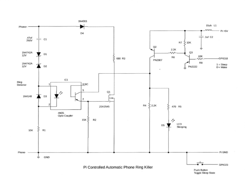
Raspberry Pi-Controlled Automatic Phone Ring Killer
Reading Time: 2 minutes“I had designed a few other projects using Raspberry Pi, so I had extra Raspberry Pi’s laying around,” Barry explains. “[I] decided to put my extra Raspberry Pi 3B+ to good use as the +5 V power source [of the] automatic timer for the phone ring killer circuit.”
In the lab
We feel like everyone needs some kind of maker room if they can manage it. Barry though is a professional.
“I have my own electronics lab in my house,” Barry mentions. “Including lots of spare parts, and very sophisticated test equipment, having worked as an independent consultant engineer for many years. That makes building these tiny projects a breeze for me.”
The tiny project involves a little more hardware than software, as it is connected directly into the phone. You can follow along to Figure 1 for the explanation by Barry on how it works.
“The telephone line attaches to the Ring Detector (components C1, D1, D2, D3, R1, and the input to IC1 the optocoupler). Zener diodes D1 and D2, combined with capacitor C1, allow only high-voltage AC signals to reach the input of the optocoupler. Normal voice and dialling tones don’t affect the ring detector at all. The Ring Signal satisfies these high-voltage AC requirements as it is an 80 V RMS (113 V zero to peak) AC signal superimposed on the 47 V DC idle phone line voltage.
“When the phone rings, the input of the optocoupler gets activated. The output of the optocoupler then turns on driving R2 to nearly 5 V DC into the gate of the MOSFET Q1, which momentarily loads down the telephone line with 680 ohm resistor R3 signalling the phone company to shut off the ring signal. This happens so fast that you don’t even hear the phone ring. This describes the operation of the circuit when it is in the ‘Sleep’ mode.”
The Raspberry Pi controls switching sleep mode on or off via powering GPIO pins with a Python program that gets the time from NTP (Network Time Protocol). There’s also a manual toggle in case you’re going to bed early.
Like a baby
“I get a much better night’s sleep just knowing that I will not have my slumber interrupted by another annoying telemarketing call at six in the morning,” Barry tells us.
When we asked about the success of the project, Barry seems not to think there’s much mass appeal for a project like this, as everyone just uses ‘do not disturb’ on their smartphones. While perhaps true, we still think there are plenty of folks who would love to have some manual control over their old landline.
-
Cosmic Unicorn (Pico W Aboard) review
Reading Time: 2 minutesAs with the Galactic Unicorn, it comes preloaded with Pimoroni’s own brand of Pico MicroPython firmware and an auto-running demo program that lets you press one of four tactile buttons to choose from four graphical effects: burning flames, eighties supercomputer (random pixels), cycling rainbow, and nostalgia computer prompt.
Again, the Pico W RP2040’s PIO state machines are used – along with 12 FM6047 constant current LED drivers – to control the 3.5 mm pixels at around 300 fps at 14-bit resolution, so there’s no sign of any flicker.
Sounds good
At the rear you’ll find a small 1 W audio speaker along with two Qwiic/STEMMA ports (JST-SH) for connecting breakouts such as sensors. There’s also a battery connector (up to 5.5 V). Positioned at the right-hand edge of the front is a phototransistor to detect light levels. Two metal legs are supplied to use as a stand.
Programming is relatively simple using the PicoGraphics library for shapes, sprites, and a selection of fonts. Check out the full function list in the Cosmic Unicorn MicroPython reference guide. Inspiration can be found in several code examples, including a neat web-server-based paint program for drawing on the display from a computer.
Verdict
9/10
The larger display area opens up more possibilities for projects, such as a weather dashboard, as well as for playing impressive graphical effects and animations.
Specs
Display: 32×32 matrix of RGB LEDs (1024 in total)
Features: Pico W on board, 10 × push-buttons, mono I2S amp and 1W speaker, 2 × Qwiic/STEMMA ports, battery connector, 2 × metal legs
Dimensions: 204 × 204 mm
-
Flight tracker with weather
Reading Time: 3 minutes“I originally saw someone post a flight tracker using an Arduino but it only displayed overhead flights – when there were no planes, it was a blank screen,” Adam explains. “Myniceaccount posted his own project in the comments on Reddit and it included a clock and a flight tracker using Raspberry Pi, so I followed the instructions and built one.
“Afterwards, I kept looking at the empty space and thinking it could be utilised so much more, especially since it was already pulling data from a weather website and flight tracking website. With some help with the coding, more functions were slowly added.” The result is a constantly useful device.
Raspberry Pi in the sky
Rather than use a screen, the project incorporates a 64×32 RGB matrix panel. “I liked the way it looks,” Adam says. “It’s very low key and old school while being easier to read (I think). If you had a screen, you could add more information, but it would become too cluttered. This one is simple and to the point.”
An Adafruit Bonnet controls the panel, which is covered with black tinted acrylic and housed within a case. Once the casing was cut and glued together, Adam set up his Raspberry Pi 3A+ computer and began working on the software.
“Originally the display showed the time, date, and current temperature on the main screen and the flight route, call sign, and aircraft on the other,” Adam continues. “I had the idea to add a weather forecast on the main screen and to add the airline logo, distance, and direction on the flight screen. I just needed help from someone who knew Python to put it all together.
“I found someone, but he didn’t have the setup to test it, so we spent weeks going back and forth – him sending code and me running it, then sending error reports or feedback on what was working and wasn’t working.” After making the time and date smaller, Adam dabbled with a four-day forecast only to realise three-digit temperatures messed up the screen layout. He chopped a day away.
Is it a bird?
Flight tracking remains a very important part of the project. Adam is a keen plane spotter and a device to aid his hobby was his primary motivation. To ensure accuracy, flight information is sourced from FlightRadarAPI.
“When a plane enters a predetermined ‘box’ made from two lat/long points in the config file along with a minimum altitude, it pulls the flight info and lat/long of the plane and compares it to the lat/long of your location,” Adam explains. “As the plane flies through the box, it updates its distance and direction until it’s out of the box, where it switches back to the clock and weather.”
The device now takes pride of place beneath Adam’s TV, allowing him to quickly view its information. “With this device I can hear a plane outside and I can discover what it is,” Adam says. “This project was also my first involving an actual display and casing so it was definitely a new experience for me.”
-
Paragraphica camerica
Reading Time: 4 minutesSubterranean survival
Now throw into the mix inspiration from a book entitled An Immense World: How Animal Senses Reveal the Hidden Realms Around Us (Ed Yong), and Bjørn’s thinking gets even more fascinating. The book explores how animals perceive the world differently from humans, and a specific story about the star-nosed mole resonated with him. The book describes “an intelligent hunter and explorer that navigates its world not through sight, but through touch. This creature, living in darkness, has developed a unique way of ‘seeing’ its environment using its star-shaped snout.” This story illustrated to Bjørn “how different forms of intelligence perceive the world in ways that are almost unimaginable to us.”
Challenge your perceptions
The fallout from all of this was the design and development of Paragraphica, a context-to-image camera that uses data, not light, to create images, and which offers “a different way of seeing the world, one that is based on data and AI interpretation rather than human perception.” Bjørn feels that it’s a tool that falls “somewhere between critical art and consumer product,” allowing users to explore the ‘dreams’ of AI as he sees it, “providing a glimpse into a form of intelligence that is fundamentally different from our own.”
Perhaps the most striking thing about the camera is the design of the cover on the front, where typically on a camera you’d find a lens, and we have the star-nosed mole to thank for that. Nature plays a key part in a lot of Bjørn’s designs, and this small burrowing mammal’s antenna-like snout was “the perfect inspiration for the camera.” In addition, Bjørn wanted the front of the camera to evoke a “data collector”, such as a radio antenna or satellite dish.
Bjørn’s camera works by collecting data related to its location using open APIs, including OpenWeatherMap and Mapbox. This data is used to compose a paragraph (hence the name of the camera) that details a representation of the current place and moment, and this description is then used as the AI image prompt.
“In a way, you can think of this process as filling in the blanks of a template paragraph,” Bjørn suggests. “I then send this paragraph as a prompt for a text-to-image AI model to convert the paragraph into a ‘photo’.” Some of the resulting images have been surprisingly accurate, “but they never look like the real place – it helps to think of the resulting ‘photo’ as a data visualisation.”
Bjørn wrote the software for the project, which uses a mix of a local Python script to simulate key presses, and a web application running in a browser. The web app was made using the Noodl platform, “and essentially gathers key parameters from the web, like weather, date, street name, time, and nearby places, and recomposes them into a template description.”
Dial development
A Raspberry Pi 4 powers the device from within a 3D-printed shell. “Using a [Raspberry] Pi for the project gave me the freedom to prototype fast and explore some ideas for how it would work,” Bjørn explains. “And I also had a Raspberry Pi 4 with a screen already attached to it laying in my workshop, so this felt like a good starting point.”
As with most projects that we showcase, there were challenges to overcome during development, including 3D-modelling and 3D-printing the unique mole-inspired casing, and setting up the code and API pipeline for Raspberry Pi.
Bjørn has also been tweaking the dials on the camera, which enable the user to control the data and AI parameters, thus influencing the final ‘photo’. “I have recently updated the two dials to affect the photo styles and years,” he explains. “Changing the year the photo should be taken at is particularly fun, as you get to picture your street in the 1960s, or 2077 into the future.”
View-finder
Bjørn describes the feedback received thus far as “mixed”, with the area of AI igniting a range of reactions and opinions. Some people saw it as a product, but “struggled to connect it to a problem that needed to be solved.” Others have understood the concept and absolutely loved it.
However, Bjørn feels that it “defiantly shows that the concept and manifestation hit a sensitive point.” He’s clear that his creation was intended to highlight and encourage discussion around AI perception, along with “the increasing use of AI in creative domains and technologies we use daily to capture reality. I think it did the job perfectly.
-
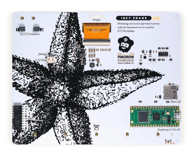
Inky Frame 7.3″ review
Reading Time: 2 minutesOther than that, it’s very similar in design to the previous Inky Frame models, with a seven-colour e-ink display with five tactile user buttons underneath. It’s based around a standard Raspberry Pi Pico W board pre-soldered to the rear of the board, so you can connect it to a computer via USB for programming, as usual. The rear also features two Qwiic/STEMMA QT ports (for attaching breakouts) and an extension header (including six GPIOs), along with a reset button, microSD card slot (extra storage for images etc.), and JST battery connector.
Slow but ultra-efficient
Like other e-ink displays, the Inky Frame 7.3˝ takes a while to refresh the screen: typically 25–30 seconds – a little longer if rendering JPG images. The big advantage is its ultra-low power drain: e-paper only uses power while refreshing. As well as keeping time, the on-board real-time clock can place Pico into an ultra-deep sleep mode that uses a tiny 20 μA until woken.
Software-wise, it’s preloaded with Pimoroni’s MicroPython firmware, including the PicoGraphics display library and several code examples. To connect Pico W to your wireless network, just fill in the SSID and password in the secrets.py file – see the Getting Started guide for more details.
Verdict
9/10
All the low-power advantages of colour e-ink combined with larger screen estate makes this a formidable display.
Specs
Display: 7.3-inch e-ink, 800×480 pixels, seven colours
Features: Pico W, 5 × user buttons, reset button, LEDs, microSD card slot, breakout header, 2 × Qwiic/STEMMA QT ports, 2 × metal legs
Dimensions: 176.2 × 139.2 mm
-
Using Raspberry Pi at home – a novelty for Rob
Reading Time: 2 minutesWhile I’ve made many, many (many!) Raspberry Pi projects over the last decade or so for tutorials and such, I still get a little extra spark of joy when I’m making something outside of a work setting. Last month I wrote a guide on how to create some interactive streaming lights with a Raspberry Pi Pico and some NeoPixel LEDs, and that had started off life as a personal project. Using it in a context outside of the magazine in my day-to-day (sorta) life has a different level of novelty to me.
In plain sight
That’s not to say I never use Raspberry Pi around the house. At the very least, I always have a Raspberry Pi NAS running in the background, and I’ve had a Raspberry Pi media PC for about as long as media centre software has been available for Raspberry Pi. These utilitarian builds live in the background though and are a bit less creative or unique.
I think that’s one of the reasons Raspberry Pi has taken off so well. You can have a functional project, a seasonal project, or a more ostentatious one and Raspberry Pi or Pico is usually the best (and cheapest) thing to use for the job. It’s also how we can have many fantastic projects each month in the showcase section at the beginning of the magazine.
One more thing
There’s always another Raspberry Pi build I want to do. Right now, I’m thinking about interesting LED customisation of a LEGO castle or a Gunpla model, and maybe upgrading the decorations on my Christmas tree. Not sure why it’s mostly light stuff right now, but I’m sure something else will pique my interest – and when it does I’ll probably get to write about it for the magazine.
Whether you have an outlet like me for your project (and I understand my situation is fairly unique) shouldn’t really matter – what matters is whether or not you turn on your project and think “oh cool, I made that.” It’s certainly helped me through other parts of my life.
-
The MagPi magazine issue #132
Reading Time: 3 minutesBuild a Universal Media Player
Turn a Raspberry Pi computer into a low-cost, but high-powered media box. Our media is far more capable than shop-bought options and plays media from a huge range of sources. Read our detailed guide to cases, remote controls and setting up media player software.
KitronikAn amazing Paragraphica AI camera
We love this unique lens-free camera build. Paragraphica gathers location information along with weather conditions and local buildings. Then feeds that into an AI model which generates a photograph. The results are often startling realistic, and always interesting.
Discover this Mona Lisa fluid painting
This remarkable Raspberry Pi project showcases a new microfluidic architecture that paints images in volumes as low as two nanolitres per spot. The image was created from just five microlitres of water ‘painted’ on a 2 cm canvas.
Create a Star Wars diorama
Become a new hope for a galaxy far, far away by recreating an iconic scene from Star Wars. This Star Wars diorama uses Raspberry Pi and a hidden screen to recreate the holograph of Princess Leia.
Starter Electronics: True or False quiz game
We continue our exploration into electronics with this guide to building a true or false quiz game. This project introduces LCD screens to our Raspberry Pi Pico electronics projects. You’ll learn all about voltage shifting to power the Raspberry Pi and screen together.
Get involved with Citizen Science
Raspberry Pi has had a huge impact on the scientific world, enabling low-cost citizen science projects. It’s small, cheap, reliable and has great community support. In this feature, we look at all the different scientific projects and programmes you can get involved with. From medicine to wildlife, geology and many other fields.
Learn to code with Kitronik ZIP96
This bare-bones PCB turns Raspberry Pi Pico into a basic retro computer. Rather than play games, you code your own for it. Instead of a LCE screen, it comes with a 12×8 LED matrix along with push-buttons.
Liverpool Makerfest
Set in the beautiful Central Library, Liverpool MakeFest is a free event that brings makers together from all over the country to enthuse about their creations, projects, and art. Roving reporter and The MagPi writer, PJ Evans spent time at Liverpool Makerfest and brings us this special report.
-
Win one of five DeskPi Pro V2 cases
Reading Time: < 1 minuteSave 35% off the cover price with a subscription to The MagPi magazine. UK subscribers get three issues for just £10 and a FREE Raspberry Pi Pico W, then pay £30 every six issues. You’ll save money and get a regular supply of in-depth reviews, features, guides and other Raspberry Pi enthusiast goodness delivered directly to your door every month.
-
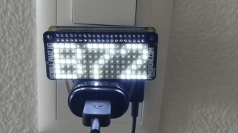
Ohsillyscope waveform display
Reading Time: 2 minutesThe project allows Thomas to play musical instruments and see the tunes visualised as waves on a 64×64 LED matrix display. “After getting the LED matrix and playing around with it, I figured there would have to be a way that I could use it with my guitar and other musical instruments,” he explains. “It’s always really fun watching the live signal from synthesiser software, but I imagined I could make something more physical with the matrix.”
Live jives
The idea, he explains, boiled down to registering a live audio signal with a Raspberry Pi computer. “Down the line, I want to make some more complicated visuals that are reactive to the audio signal coming in,” he says.
It has involved connecting the matrix panel to an Adafruit RGB Matrix HAT add-on. “I have Raspberry Pi recognise the audio interface it’s hooked up to, and I’ve used Linux’s Advanced Linux Sound Architecture (ALSA) library to read the signal from the interface and place it into the C code running the LED matrix’s library,” Thomas says. “It’s sampling at the refresh rate of the screen, which makes a really cool visual.” Learn more at alsa-project.org.
The result is a project that can be taken on the road as a visual accompaniment to musical performances. “At first, I was thinking that I could have it work through MIDI [a protocol which lets musical instruments, computers, and other hardware communicate with each other], but the idea of needing to be hooked up to the software Ableton Live killed the motivation to write an entire library to do so. I wanted something that didn’t require being by a computer to represent music.”
Looking good
Thomas loves using his creation. “It’s small and portable – something you just plug in knowing that everything is set up,” he says. “The LED matrix HAT was made for Raspberry Pi, so it was a no‑brainer. It also helped that I had a couple of Raspberry Pi Zero computers laying around begging to be used.”
Currently, he’s hooked the Ohsillyscope to the PA system in his band practice room. “It picks up the bass, guitars and drums, making an interactive show for anyone watching,” he says. “The people we’ve shown the Ohsillyscope to so far seem to love it and once we start gigging more, it’s sure to get the band more attention.” We’re definitely sure that it’s going to look good on the dance floor.
-
Chonky Pocket
Reading Time: 3 minutes“I wanted a pocket-sized Linux computer with a physical keyboard and I sort of hacked something together last year that wasn’t very nice,” Dan explains. “I decided to have another go at it this spring when I got a pre-release Amp Ripper 4000 PSU to try out.” His goal was to incorporate a keyboard, scroll wheel, and touchscreen, and include a laptop-style battery that would report its state of charge to the OS.
Key points
At the Chonky Pocket’s heart is a Raspberry Pi 4 computer. “I usually use Ubuntu and it’s great that Raspberry Pi is officially supported,” Dan says. It’s hooked up to a 5-inch HDMI touchscreen with a speaker and, of course, a handful of keys. They’re ‘chorded’ which means: several keys need to be pressed together to enter characters, words, phrases, or commands.
“The keyboard layout is mostly just the eight-key ARTSEYIO chording layout with two extra keys mapped to ‘)’ and ‘(‘ and chorded ‘:’ – keys that normally require a layer shift with the ARTSEYIO layout.” This enables Python coding. “It was a bonus that the extra keys made the keyboard physically symmetrical, so I could change the layout for either hand,” Dan adds.
Of course, it’s going to take some getting used to. “I can type about 20 words per minute (wpm) with it when I practise a bit, but there are folks on the ARTSEYIO Discord who can do more than 40 wpm,” Dan continues. “If I wanted to type faster with one hand, I’d be inclined to use half of a Corne split keyboard (CRKBD) which has more thumb buttons for layer shifting and more direct access to symbols, numbers, and CTRL/SHIFT/ALT.”
Powering on
The build posed some challenges. “Modifying the battery kernel module for this was interesting,” Dan says. “I haven’t touched any C code since college and the window manager would crash when I loaded the module in Raspberry Pi OS. I’m just lucky that it worked in Ubuntu without having to do much troubleshooting.”
Power was hard to get right too. “Even using the wrong connector between a battery and the boost/charge board can cause voltage warnings and rebooting with Raspberry Pi 4,” he explains. And he has rewritten the GPIO keyboard firmware a couple of times. “It was an opportunity to learn about the current state of GPIO programming on Raspberry Pi with ‘lgpio’ and figure out how to use ‘uinput’.”
Dan hopes many people will enjoy building their own version and already plans for a build that includes a second HDMI port, external pins, a display that turns off when idle, and more. “I’ve gotten lots of supportive comments on Reddit for this build and some nice media coverage. It’s been a lot of fun,” he says.
-
u-maker box Raspberry Pi case review
Reading Time: < 1 minuteWhat’s cool, though, is that you can really modify and personalise the case to what you need it to do thanks to a smart construction system and freely available templates to play around with for 3D printing.
Snap build
The standard box comes with some mounts that allow you to attach it to a wall or VESA mount, and even a special one for boom arms. As well as the extra bits in the Extension Kit that help connect extra boards, brackets, or even a case fan, there’s a ton of Thingiverse files for various kinds of stands, extenders, and even an alternate lid that can fit a square HyperPixel.
The number of options are truly astounding and none of it looks or feels hacky. It’s just a very nice implementation of the design idea.
Verdict
10/10
A unique and very cool way to customise or prototype a case for your Raspberry Pi projects.
Specs
Dimensions: 120.4 mm × 120.4 mm × 35.5 mm
Weight: 93.2 g
Fasteners: Magnetic
-
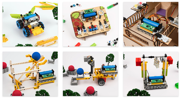
WuKong 2040 breakout board review
Reading Time: 2 minutesAt under £10, the WuKong 2040 certainly keeps prices low while still packing a huge array of features on a small board. Buzzers, buttons, LEDs, motor controllers, a traditional GPIO breakout to hook up more, and the ability to power it all with a rechargeable battery so you can take it anywhere.
Code by numbers
Programming a Pico attached to the board is quite simple, making use of standard MicroPython, CircuitPython, and C libraries to work, and each pin and component labelled with the corresponding GPIO to which it’s connected. Examples are given in CircuitPython on the website, which can be fairly easy to translate to MicroPython if needed, and give you a nice little overview of what you can do with the board.
For those wanting a more practical application of the board, it also comes with a little add-on that makes the base compatible with many kind of brick building systems like LEGO – a good way to create a fun robot completely powered by custom code you made yourself.
Verdict
9/10
Small, reasonably priced, and packed with functionality, this board is a fun way to learn and grow with Pico.
Specs
Size: 55.8 × 87.8 × 36.3 mm, 50 g (without Pico or battery)
Power: 18650 lithium battery
60-minute battery life
2.8 V ~ 4.2 V
Interfaces: 2 × buttons, 2 × LEDs, 1 × buzzer, motor interface, GPIO interface, I2C interface
-
Trainbot/OnlyTrains
Reading Time: 4 minutesRoom with a view
Jonathan first came across Raspberry Pi when he was still an electrical engineering student back in 2014. He promptly put his first Model A Raspberry Pi to good use controlling the door to a co-working space at the ETH Entrepreneur Club where he was a member, using Slack. There isn’t much call for the computer vision skills that were part of his degree course, but Jonathan enjoys creating projects that exploit his technical knowledge.
When Jonathan moved into his apartment two years ago, he quickly realised that the unique view it gave him of the trains going by would make for an ideal project subject. “Inspired by the slit-scan finisher photographs from bike races, I then came up with the idea of creating pictures with similar aesthetics – but of trains instead of bikes, and a cheap camera instead of specialist hardware,” he explains. Slit-scan photography creates an animation from a series of still shots. For his train version, Jonathan was keen to use the Go programming language’s computer vision and cross-compilation tools, and see how well it worked alongside older tech such as SQLite and FTP.
Jonathan chose Raspberry Pi 4 to run Trainbot, as “it offers all that is needed for such a project: quite a lot of compute power, cheap, good ergonomics and docs, and good software support.” It is also powerful enough to handle the graphical computations required, while being less expensive than a board with a dedicated graphics processor. He notes that “the computer vision used in Trainbot is fairly naïve and simple. There is no camera calibration, image stabilisation, undistortion, perspective mapping, or ‘real’ object tracking.”
Name that train!
With plenty of Raspberry Pi and Linux experience under his belt, Jonathan’s challenges for the Trainbot included creating mounting plates and other small parts to fit inside the waterproof case he bought, so the AI camera setup could live outdoors on his balcony, as well as developing and testing the computer vision algorithm. He needed data with which to train the algorithm and spent “quite some time” recording video with his phone first, before “semi-manually chopping up the recordings and setting a test harness with them”.
There was also a lot of “testing and tuning” involved in ensuring the computer vision setup was able to recognise most trains. “I soon figured out that patch-matching alone is not robust enough to estimate train velocity.” Jonathan notes that this led to missed frames, or wrongly estimated ones, which led to chopped-up images. To address this, he added a step after the initial image gathering which applied an estimation and smoothing process using RANSAC and “ a simple s = v0 + a*t model” to estimate start velocity and acceleration. RANSAC is a classical computer vision approach used to estimate a model when there are lots of outliers. He wrote much of the code himself, including instructions for patch-matching and the low-level computer vision, to keep things as light as possible.
With half of the coding and cross-compilation done in Go, Jonathan tried out Trainbot on his Raspberry Pi. At first, the project used a webcam but, as soon as Jonathan realised Raspberry Pi also makes camera modules, he switched over to HQ Camera Module 3, resulting in “much higher image quality (and very good software support via libcamera) than a cheap webcam, at a low price point.” Next, he intends to develop the machine learning element to recognise and highlight ‘atypical’ trains, something that will be aided by him also adding details from the GTFS+/GTFS real-time timetables available in machine readable format from Swiss public transport companies.
-
Badger 2040 W (Pico W Aboard) review
Reading Time: 2 minutesTalking of power, you will want a portable way of supplying it. To this end, there’s a JST battery connector on the rear. If you buy the accessory kit version, you get – along with a lanyard – a 2×AA battery pack with a Velcro patch to stick it to the rear of the board.
Alternatively, you could use a standard USB power bank connected to Pico W. Both solutions are a little chunky, though, so you might prefer a slimline LiPo battery pack.
Easy to program
When first powered up, the Badger 2040 W launches into ‘Badger OS’ with a scrollable menu of icons to choose demo programs and tools. These include a badge, digital clock, e-book reader, interactive checklist, news headlines, and weather dashboard.
Naturally, you can connect Pico W to a computer via USB to customise the examples or create new programs – in MicroPython or C/C++. Pimoroni’s standard PicoGraphics library makes it easy to add bitmap images, and several fonts are supported. You’ll need to add your Wi-Fi credentials to try out examples such as news and weather, as well as setting the correct time via NTP.
Verdict
8/10
An interactive badge that doubles as a versatile mini e-ink display with a reasonably quick refresh rate and Wi-Fi connectivity.
Specs
Display: 2.9-inch e-ink, 296×128, monochrome
Features: Pico W, 5 × user buttons, reset button, LEDs, Qwiic/STEMMA QT port
Dimensions: 85.6 × 48.7 × 10 mm