Schlagwort: tech articles
-

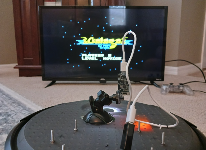
Fixing Galaga
Reading Time: 2 minutesIt’s like a Rube Goldberg machine from Looney Tunes or Wallace and Gromit, and we think it also crosses the boundary into modern art too. Nick says he hates to throw away electronics, and likes to repurpose them if he can’t fix them, which has resulted in this interesting fix. What a…
-

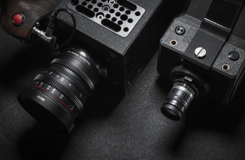
CinePI XL
Reading Time: 3 minutesBig ambitions Csaba says that CinePI was always intended to push the possibilities of Raspberry Pi as a video camera with features found in cinema cameras, but in an open-source device so developers could integrate it into their own designs. CinePI V2 can record 2K RAW Cinema DNG video at frame rates…
-

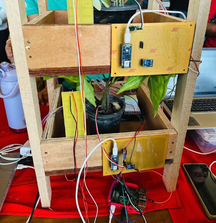
Smart vertical farming
Reading Time: 2 minutes“The inspiration came from the need to address the challenges in traditional farming and leverage technology for efficient crop management,” Tanay explains. “It’s a forward-thinking approach to agriculture and my project was born out of a passion for sustainable agriculture. The aim was to explore innovative solutions, driven by a desire to…
-

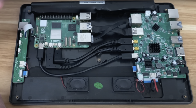
World’s First Raspberry Pi 5 tablet
Reading Time: 2 minutesYou can watch the ‘First Raspberry Pi 5 tablet’ build on YouTube. Tight fit The project began with disconnecting the fan wires from the GPIO on Raspberry Pi 5 and unscrewing the standoffs. The Ethernet and USB 3.0 cables inside the RasPad are quite short, so they were a little more stretched…
-

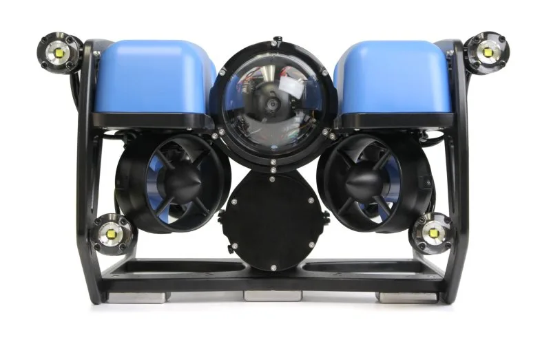
BlueROV2 R4
Reading Time: 2 minutesWhat is an underwater ROV? If you’re not sure what an underwater ROV is, the short answer is: a Remotely Operated Vehicle you chuck in the sea. But if you’re our favourite kind of geek and wish to feast on a much longer answer, Blue Robotics has shared a short history and…
-

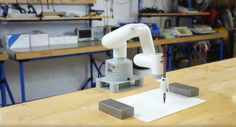
MyCobot 280 Pi review
Reading Time: 3 minutesA sixth joint rotates the end of the head, to which you can attach various accessories using tiny LEGO connectors inserted into its grid of holes and those on the accessory, making them easy to fit and remove. A similar LEGO connection system is used on the bottom of the robot to…
-

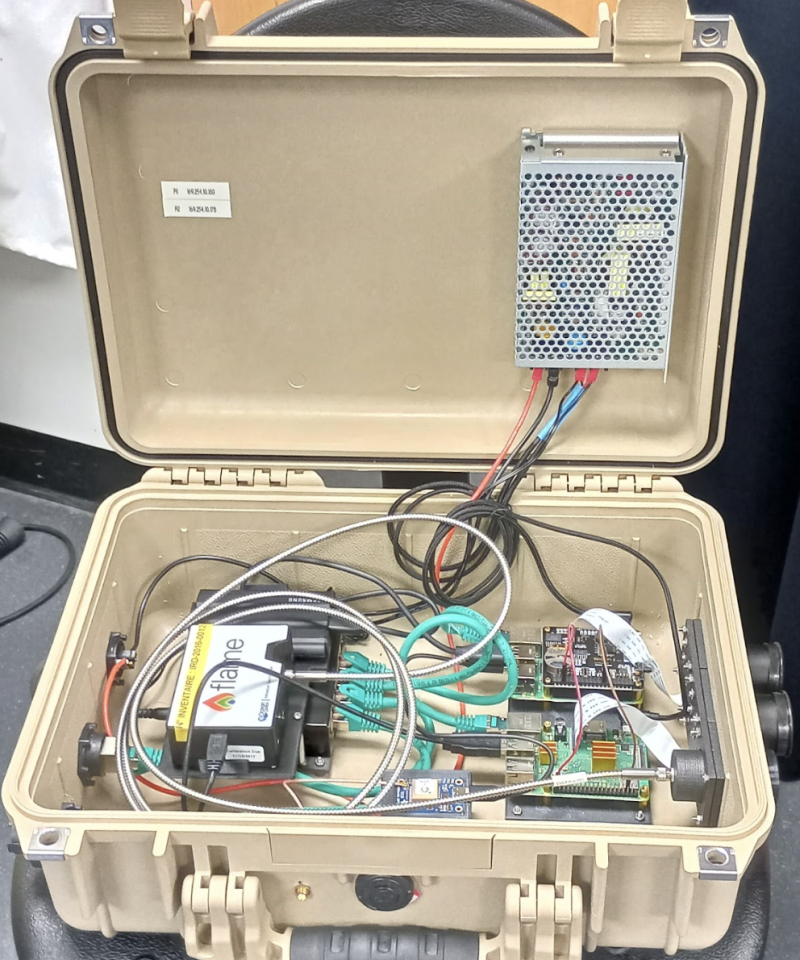
Volcano-monitoring Ultraviolet PiCam
Reading Time: 3 minutesThe two Toms continue to work together and are both members of Sheffield-based VolcanoTech. They aim to get more instruments onto volcanoes and acquire unprecedented long-term datasets that contribute to volcano research and monitoring. Designing and constructing low-cost scientific instrumentation is crucial for developing countries, where funding for equipment can be quite…
-

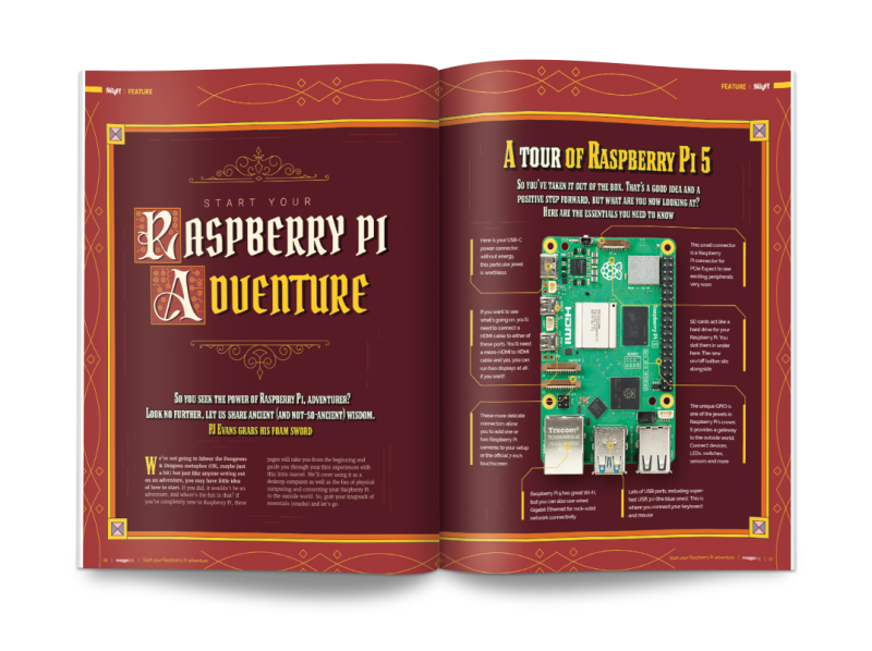
Set forth with Raspberry Pi in The MagPi magazine issue #137
Reading Time: 3 minutesStart your Raspberry Pi adventure We may be a little heavy-handed on the Dungeons & Dragons metaphor this month. This guide to beginning your Raspberry Pi is packed with information, hints, and things to discover with your favourite computer. It’s the perfect guidebook for Raspberry Pi newcomers. Raspberry Pi Beginner Projects We…
-

Win one of five U-Maker Box Raspberry Pi cases
Reading Time: < 1 minuteSave 35% off the cover price with a subscription to The MagPi magazine. UK subscribers get three issues for just £10 and a FREE Raspberry Pi Pico W, then pay £30 every six issues. You’ll save money and get a regular supply of in-depth reviews, features, guides and other Raspberry Pi…
-

Pretty tide clock
Reading Time: 3 minutesFor us landlubbers, tides aren’t always something we have to think about, although Levi was familiar with the tide clocks where he grew up. Not being able to find one for his new Californian home, Levi decided to make his own: “It displays current tide height in feet, predicted hours until next…
-

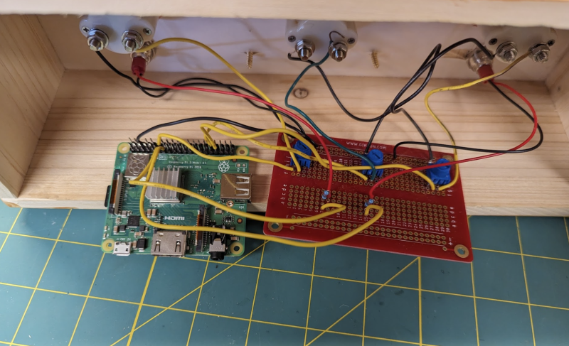
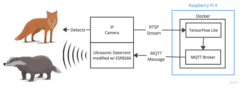
Badger and Fox Deterrent
Reading Time: 3 minutesHe had a number of Raspberry Pis at home and built a solar-powered watering system using Raspberry Pi A+ back in 2015. He says the low-powered footprint paired with the significant compute capabilities of Raspberry Pi 4 prompted him to explore its machine learning potential at home. Inaudible alarm bells Having moved house in…
-

PicoVision (Pico W Aboard) review
Reading Time: 3 minutesPower is connected using Pico W’s micro USB port – as usual, you can hook this up to a computer for programming in MicroPython or C/C++, or flashing Pico W with new firmware. Alternatively, PicoVision can be powered via two unpopulated pins. There’s also a breakout header for CPU and GPU debugging,…
-

rePalm
Reading Time: 4 minutesWith an ongoing fascination with PalmOS – “it was the first mobile OS with any sort of success and it gave the world the term ‘smartphone” – Dmitry says he wanted to see if he could put the operating system on another device with minimal changes. He looked into emulating the hardware with…
-

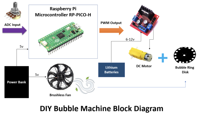
Pico Bubble Machine
Reading Time: 2 minutesAt its simplest, washing up liquid and a loop in which to form bubbles is all that’s needed to create this low-cost and playful distraction. But having set a precedent delighting pupils with her builds and science experiments, Aula was determined to design something that would catch their imagination while also encouraging…
-

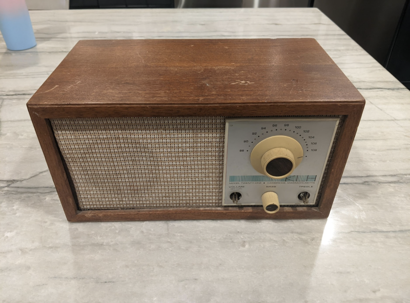
Retro Pi World Radio
Reading Time: 3 minutesDespite his thoroughly modern career as a software engineer in Silicon Valley and a CV that lists VMware and Google among his credits, Raju has a fondness for the old days. “I have always loved to tinker and repurpose old hardware to build something new”, he says, favouring Raspberry Pi boards because…
-
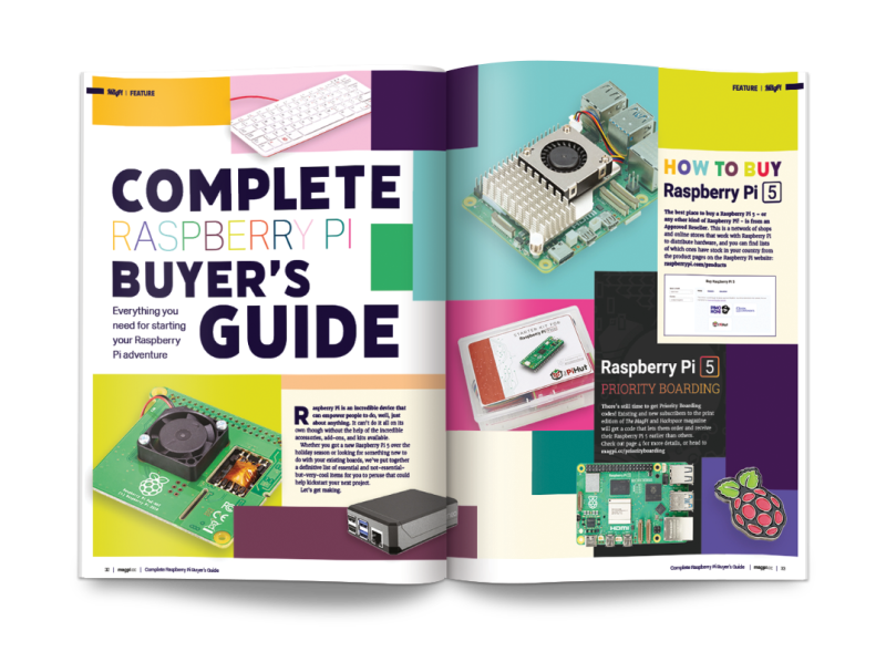
Complete Buyer’s Guide in The MagPi magazine #136
Reading Time: 2 minutesComplete Raspberry Pi Buyer’s Guide Everything you need to have fun with Raspberry Pi in 2024. We’ve got official accessories, third-party kits, cases, projects, circuits, robots and 3D printing projects. There’s enough here to keep any Raspberry Pi fan quiet for a while. Heating and cooling Raspberry Pi 5 Raspberry Pi 5…
-

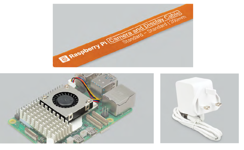
Win one of ten Raspberry Pi 5 accessory kits
Reading Time: < 1 minuteSave 35% off the cover price with a subscription to The MagPi magazine. UK subscribers get three issues for just £10 and a FREE Raspberry Pi Pico W, then pay £30 every six issues. You’ll save money and get a regular supply of in-depth reviews, features, guides and other Raspberry Pi…
-

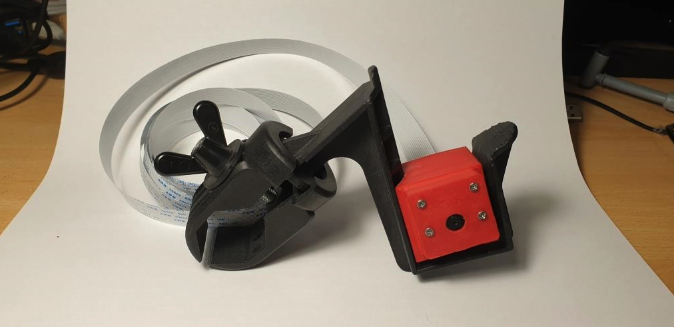
Gutter Probe
Reading Time: 3 minutesWith a bit of deductive reasoning, Peter figured out that the plant was blocking the joint, so the rainwater would just overflow. He didn’t want to hire expensive equipment to confirm this theory, though. “I then had the bright idea of mounting a Raspberry Pi Camera on the end of a long…
-

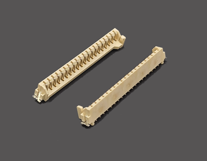
ClipZin PCB connector review
Reading Time: < 1 minuteWhile you could always just solder Pico’s castellations directly onto metal contact pads on the surface of another PCB, ClipZin has the advantage of being able to clip the board in and out at any point – ideal for when you’re prototyping a design or want to later replace a standard…
-

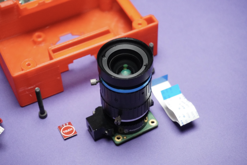
Instant Framed Camera
Reading Time: 4 minutesA flash of inspiration Using a Raspberry Pi Camera Module 3, a couple of Raspberry Pi 3 Model A+ boards, and some Python code, along with the other required bits of hardware, Max has essentially created a camera within a camera here, as a digital camera is hidden within the body of…
-

TouchCam camera
Reading Time: 3 minutesIterate and improve Designing the TouchCam gave Mukesh a chance to combine his skills as a maker and a computer science enthusiast. “My goal was to blend my love for creating things with my technical knowledge,” he enthuses of the versatile device “that can even work as a server for my test…
-

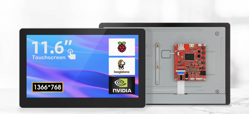
CrowVision touchscreen review
Reading Time: 2 minutesSlim and flexible There is a small price to pay for the nice screen with touch capabilities, and that is with resolution. Perhaps we’ve been spoiled by modern consumer electronics, but 1366 × 768 does not seem like a lot of pixels, especially on a screen this size in 2023. It’s definitely…