Schlagwort: retro pie

  • RetroPie for Raspberry Pi 4: video game emulation on our fastest-ever device

    RetroPie for Raspberry Pi 4: video game emulation on our fastest-ever device

    Reading Time: 2 minutes

    For many of you out there, your first taste of Raspberry Pi is using it as a retro gaming emulator running RetroPie. Simple to install and use, RetroPie allows nostalgic gamers (and parents trying to educate their kids) the ability to play old-schoolskool classics on any monitor in their home, with cheap USB game controllers or models from modern consoles.

    GuzziGuy RetroPie Table

    Mid-century-ish Retro Games Table’ by Reddit user GuzziGuy

    And because our community is so wonderfully inventive, Raspberry Pis running RetroPie have found themselves in homebrew gaming cabinets, old console casings, and even game cartridges themselves.

    [Original Showcase Video] Pi Cart: A Raspberry Pi Retro Gaming Rig in an NES Cartridge

    I put a Raspberry Pi Zero (and 2,400 vintage games) into an NES cartridge and it’s awesome. Powered by RetroPie. — See the full build video: https://www.yo…

    Along came Raspberry Pi 4

    When we announced Raspberry Pi 4 last year, a much faster device with more RAM than we’d previously offered, the retro gaming enthusiasts of the world quickly took to prodding and poking the current version of the RetroPie software to get it to work on our new, more powerful computer. And while some succeeded, those gamers not as savvy with manually updating the RetroPie software had to wait for a new image.

    Retro Pie 4.6

    And so yesterday, to much hurrah from the Raspberry Pi and retro gaming community, the RetroPie team announced the release of image version 4.6 with beta Raspberry Pi 4 support!

    One of the biggest changes with the update is the move to Raspbian Buster, the latest version of our operating system, from Raspbian Stretch. And while they’re currently still advertising the Raspberry Pi 4 support as in beta, version 4.6 works extremely well on our newest model.

    Update today!

    Visit the RetroPie website today to download the 4.6 image, and if you have any difficulties with the software, visit the RetroPie forum to find help, support, and a community of like-minded gamers.

    Website: LINK

  • Raspberry Pi 3 NES Classic Mini Project

    Raspberry Pi 3 NES Classic Mini Project

    Reading Time: 4 minutes

    The Raspberry Pi 3 NES Classic Mini Project was in our mind from day one when the new New Classic Mini arrived 🙂

    After so much time there is a company from new york making small pi cases looking like this:

    Perfect case for our project , so here is the full list what you need:

    Optional:

    Setting up the Raspberry Pi + Case Assembly

    We got this nice PDF Document from oldskool.tools that shows very nice how to assemble the case right.

    Here is the Download Old Skool Tools Setup Tutorial

    Needs:

    • Controller
    • HDMI/DVI monitor or TV
    • HDMI cable
    • Laptop or PC with SD port
    • Micro SD card
    • Raspberry Pi case + Raspberry Pi
    • USB Keyboard
    • USB micro power supply (preferably the official Raspberry Pi power supply)

    Downloads:

    SETUP

    1. Insert your SD card in the SD card slot of your laptop or PC
      (Note the drive letter assigned to the SD card, for example G:)
    2. Unzip the downloaded RetroPie project SD card image with an extraction program
    3. Extract the RetroPie project SD card image to the SD card. Be careful to select the correct drive
      (Win32DiskImager for Windows and ApplePi-Baker for Mac)
    4. Remove the SD card from your laptop or PC
    5. Insert the SD card, one of your controllers and your keyboard into the Raspberry Pi
    6. Plug in the HDMI cable then plug in the power supply. This will boot up your Raspberry Pi
    7. Follow the onscreen prompts with your controller to set it up (up, down, left, right, etc)

      Done!

    RetroPie doesn’t show the emulators that don’t have ROMs installed, so don’t worry when you notice that only a small number of emulators are available. This is how it’s supposed to work. The other emulators will show up as you add ROMs. Make sure to download some ROMs and we’ll show you how to transfer them to your Raspberry Pi.


    TRANSFER ROMS

    TRANSFERRING ROMS TO RETROPIE

    You are almost ready to begin your journey back in time. Now that you’ve dealt with the setup of RetroPie, it’s time to transfer your favorite games to your Raspberry Pi. There are multiple ways to transfer your ROMs to your Raspberry Pi, but we’re going to show you two methods:

    – Transferring ROMs via a USB stick
    – Transferring ROMs via SCP

    USB METHOD

    Needs:

    • USB stick (formatted to FAT32)
    • Raspberry Pi (powered on)
    • USB keyboard

    Setup:

    1. Insert the USB stick in your computer
    2. Make sure that your USB is formatted to FAT32
    3. Create a folder called retropie on your USB stick
    4. Remove the USB stick from your computer
    5. Plug your USB stick in your Raspberry Pi and wait for your USB stick to stop blinking (If your USB doesn’t have a light just wait 5 minutes to be sure)
    6. Take your USB stick out of your Raspberry Pi and plug it into your computer
    7. Add the ROMs to their respective folders (in the retropie/roms folder on your USB stick)
    8. Plug your USB stick back into your Raspberry Pi
    9. Wait for your USB stick to stop blinking then remove your USB from your Raspberry Pi
    10. Refresh emulationstation by pressing F4, or choosing quit from the start menu

    SCP METHOD

    Needs:

    • Ethernet cable (wired)
    • Raspberry Pi > = 3 or Raspberry Pi < = 2 with a WiFi dongle (wireless)
    • USB keyboard

    Downloads:

    Setup:

    1. Open WinSCP or Cyberduck
    2. Setup the following
      File Protocol: SCP
      Host name: the IP address of your RetroPie.
      (To find the IP address of your RetroPie, go into RetroPie options from the main menu, and select the last option [ Show IP address ] )
      Username: pi
      Password: raspberry
    3. Drop the files in the ~/RetroPie/roms/$CONSOLE folder, where $CONSOLE is the name of the target console (e.g. snes or arcade)

    After Setting Up your Retro Console the next thing to do and last thing is the black ducktape, for the true NES design 😉

    Here are some Photos of ours finished , with controllers and all you need:

    And now you know what the black tape is good for ^^

    We hope you liked our small and quick project, follow our other channels. Thank you for reading.

    Sources: http://www.8bitdo.com/

    http://retro-bit.com/

    https://www.oldskool.tools/


  • PiBoy3 – Selfmade Arcade Gaming Handheld for under 120$ – TUTORIAL

    PiBoy3 – Selfmade Arcade Gaming Handheld for under 120$ – TUTORIAL

    Reading Time: 4 minutes

    First of all a Happy New Year to all our Community here on blogdot.tv and on our Social Channels 🙂

    We are back in the new year with a quick made tutorial for everyone who wanted to make a game boy by your self ^^ so let’s start…

    THIS TUTORIAL IS BASED ON GETTING THE TFT TOUCH SCREEN WORKING WITH FULL HW SUPPORT / 60FPS AND OPENGL SUPPORT!!!  THIS IS NOT A DESIGN TUTORIAL…
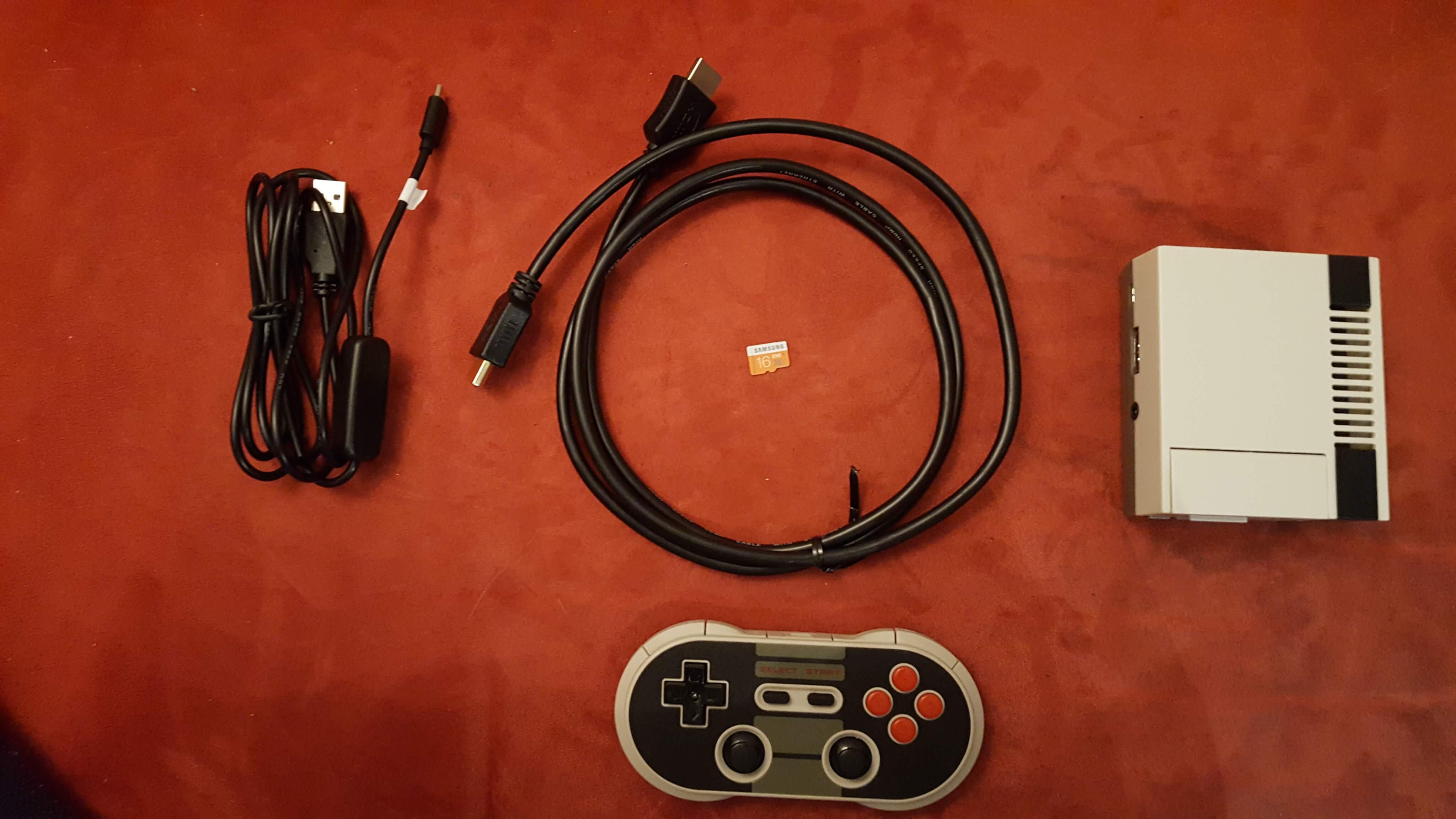
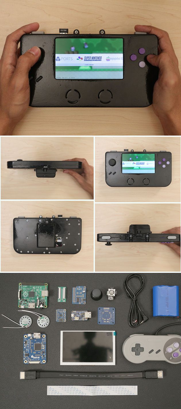
     

    Parts List:

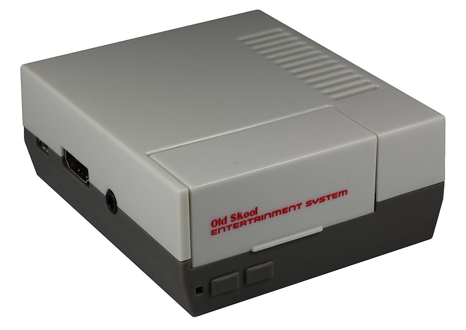
    37€ – Raspberry Pi 3 (better take a 3, with built in wifi and bluetooth) https://www.cyberport.at/raspberry-pi-3-modell-b-1-gb-1123-00G_544.html 

    33€ – TFT Screen for Pi (we took the Waveshare32, 3.2 Inch Toch Screen, inlc. 3 GPIO Buttons) https://www.conrad.at/de/raspberry-pi-display-modul-schwarz-rb-tft32-v2-raspberry-pi-a-b-b-raspberry-pi-1380381.html

    10€ – 16 GB Micro SD Card (Take a fast one) https://www.conrad.at/de/microsdhc-karte-16-gb-sandisk-ultra-android-mit-80-mbs-und-sandisk-memory-zone-android-app-class-10-uhs-i-inkl-sd-adapter-inkl-android-software-1381008.html

    15€ – 6.000 mAh Battery Pack with overvoltage surge (you need one with at least 2.0A output!!!) https://www.conrad.at/de/powerbank-zusatzakku-varta-powerpack-family-6000-li-ion-6000-mah-1424864.html 

    15€ – Speakers (those are the most problem because of the size, we found some old passive speakers from our old nokia mobile phone that we are using right now) these here are good to open easy https://www.amazon.de/dp/B01MYU3780?psc=1

    10€ – Speaker Alternative: https://www.conrad.at/de/raspberry-pi-erweiterungs-platine-blau-sbc-soundmodule-raspberry-pi-raspberry-pi-2-b-raspberry-pi-3-b-raspberry-pi-a-raspberry-pi-b-raspberry-pi-1503744.html

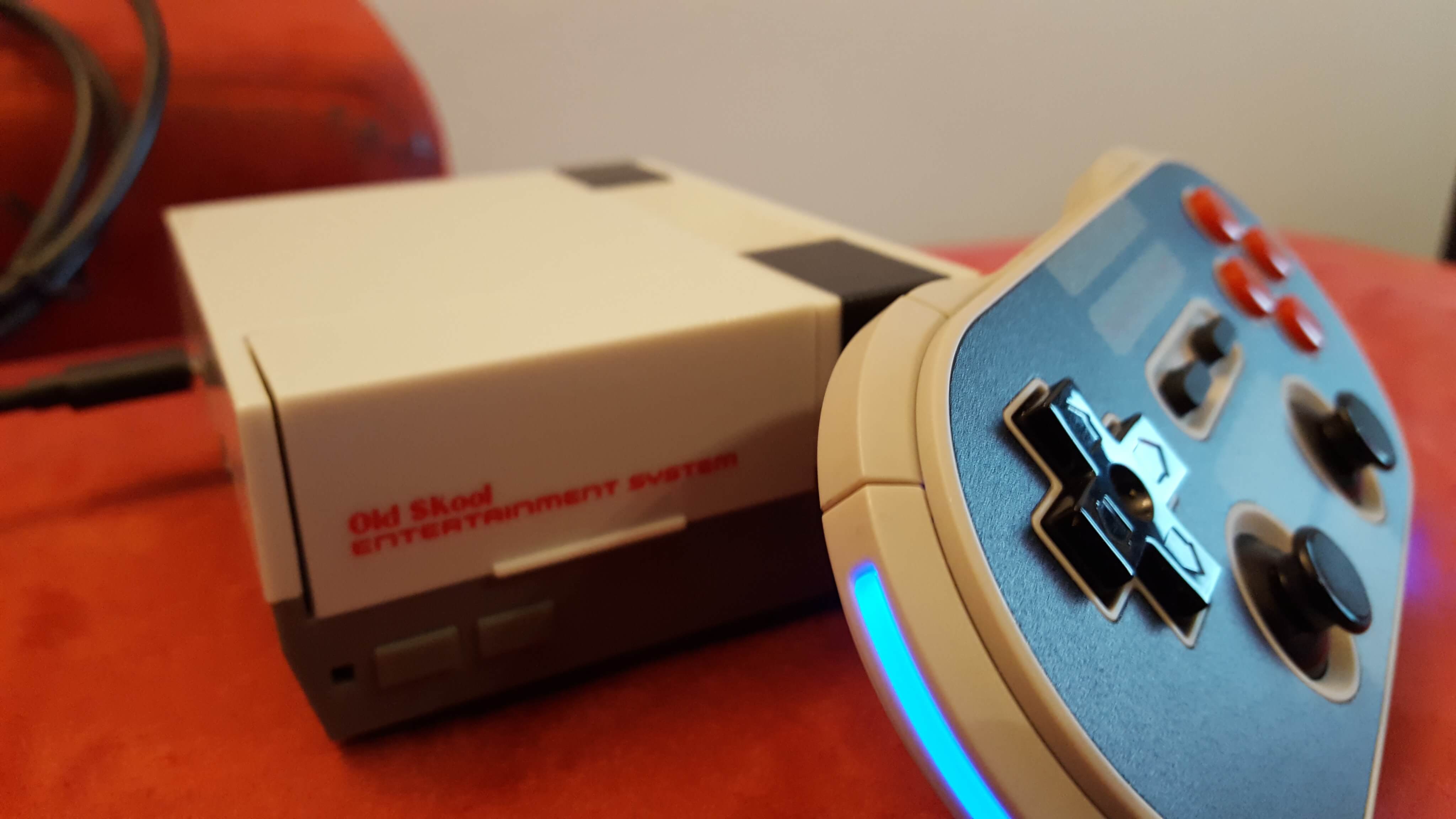
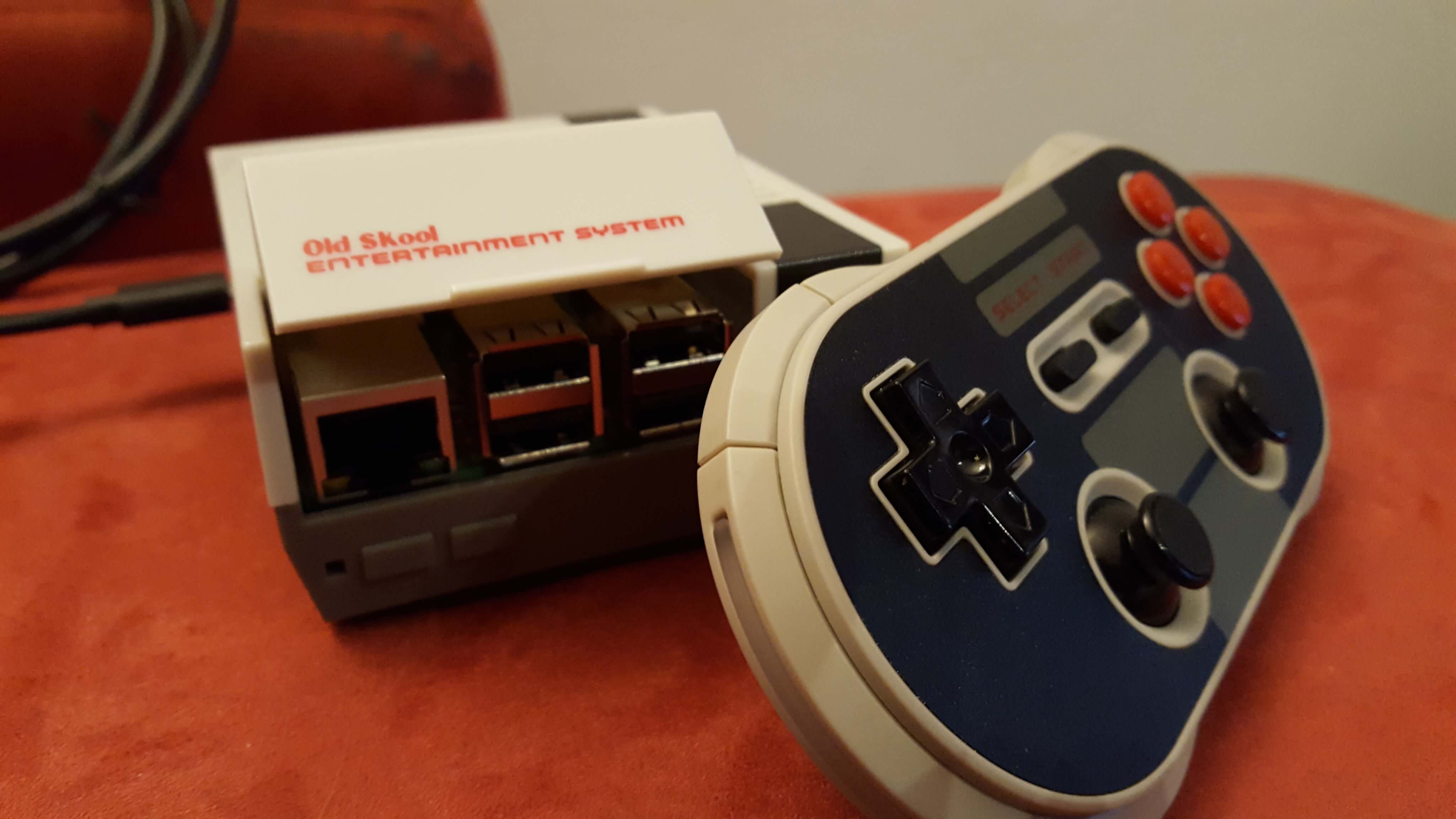
    10€ – SNES Retro Usb Controller (you can choose the style we took an old one , laying around ) https://www.amazon.de/CSL-Gamepad-Controller-Notebook-Retro-Design/dp/B00HFQEFTY/ref=sr_1_2?ie=UTF8&qid=1484006798&sr=8-2&keywords=snes%2Busb%2Bcontroller&th=1


    SW List:

    Retropie Image: https://retropie.org.uk/download/ we used retropie 4.1 in our tutorial

    TFT Screen Driver: http://www.produktinfo.conrad.com/datenblaetter/1300000-1399999/001380381-an-01-de-8_13_CM__3_2__TOUCH_DISPLAY_320X240_PX.pdf


    Installing Retropie

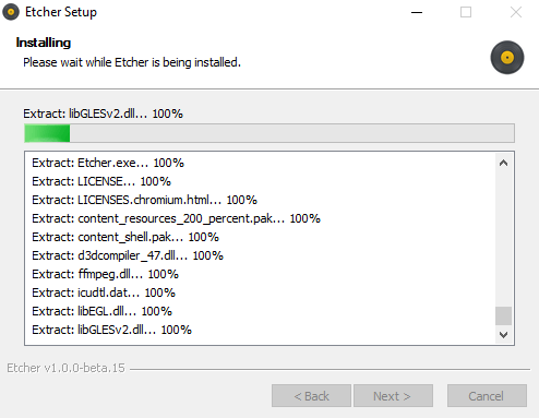
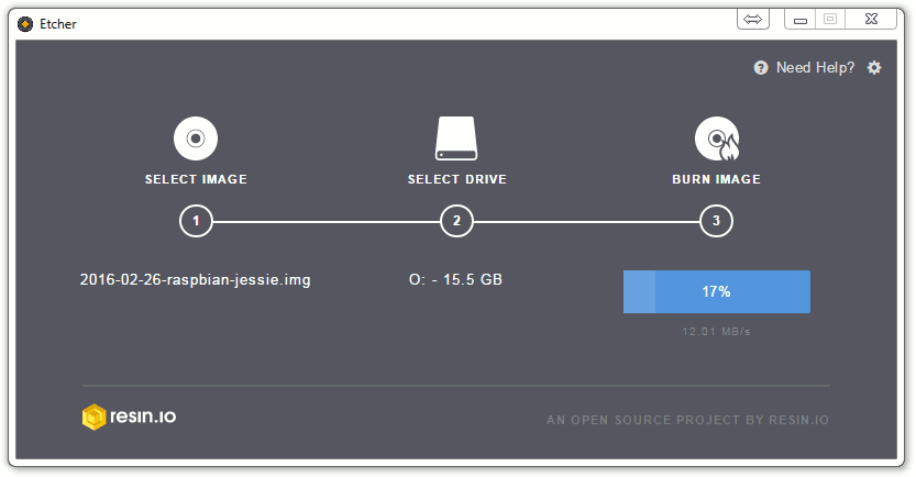
    Download the Raspberry Pi Image from the Link above, and flash it with ETCHER (Win/Unix/Osx) https://etcher.io/ to your 16 GB SD Card.

    This will take a while….


    When finished , let’s get to the assembling 🙂


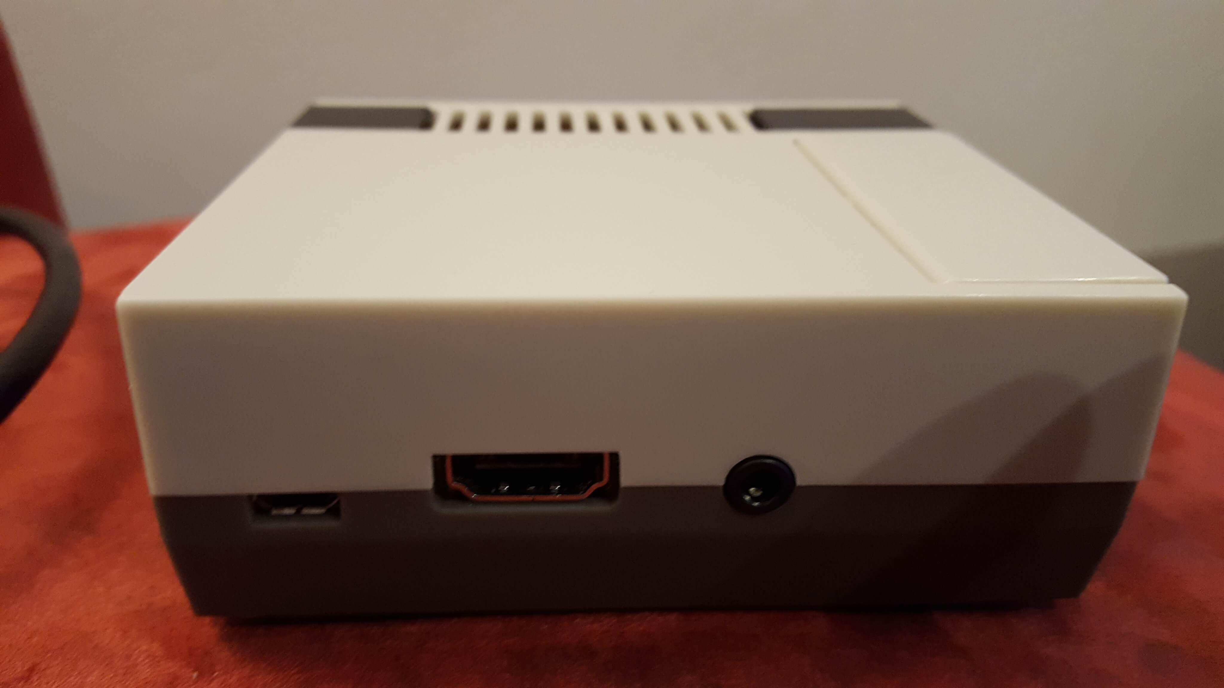
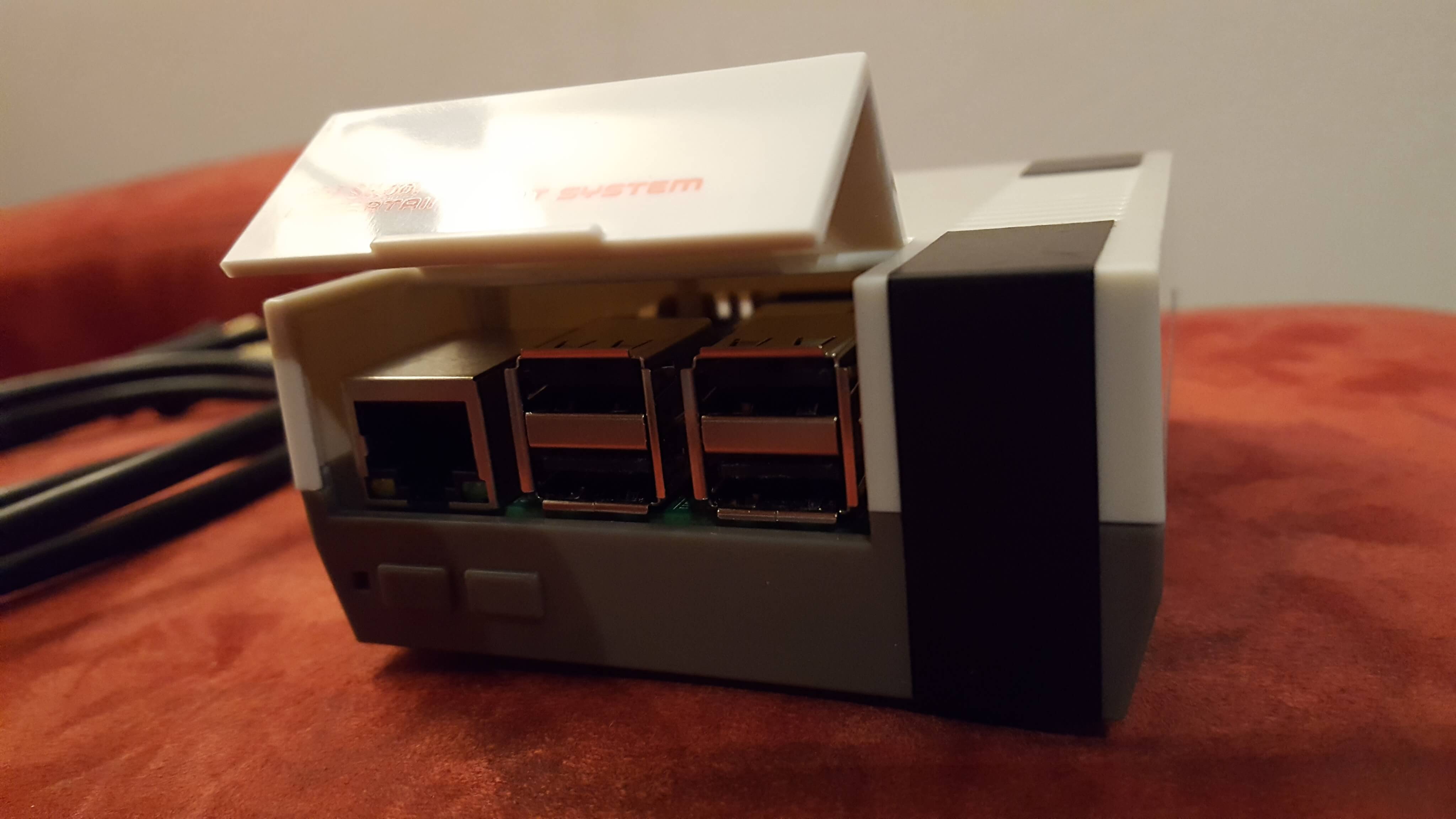
    Assembling the PiBoy3

    This is a nice funny video from Element 14 how to use the raspberry pi 3 cases with the pi, and also how to hock up all the cables, we really like it…


    We just need the part to understand how to assemble the case, and also only for those people that never had a Raspberry pi in their own hands by now.
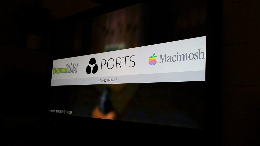


    First Run:

    Your Pi Setup with retropie hocked up to a screen and everythingyou can start you raspberry pi 3.

    First it will resize your image on its own, so you don’t need to do it.

    Second part is emulationstation where it wants to configure a controller, if your controller is hocked up you can set it up, or you can cancel it and leave it for later.

    we gonna leave emulation station, you gonna do that with ‚ctrl‘  +  ‚alt‘ F4 this should open a new terminal where you should be loged in automaticaly, if not the user is ‚pi‘ and the password: ‚raspberry‘

    now we can update the pi for our tft screen to work!

    Installing the TFT Screen


    first we gonna edit the config.txt

    sudo nano /boot/config.txt


    add at the end of the line:


    dtparam=spi=on
    dtoverlay=waveshare32b:rotate=270  

    (THIS IS ONLY FOR THE WAVESHARE TFT DISPLAYS)

    after this edit, let’s restart so the screen turns from white to black that’s good 🙂

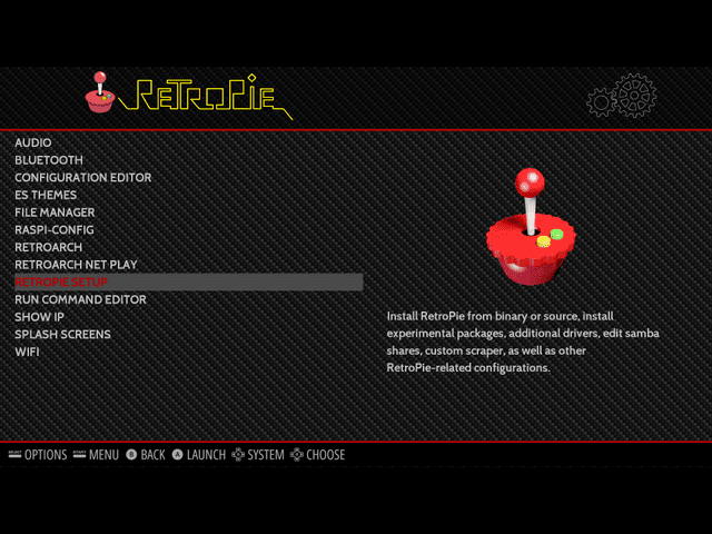
    back in emulationstation go straight into the only menu entrance retropie and choose retropie-setup

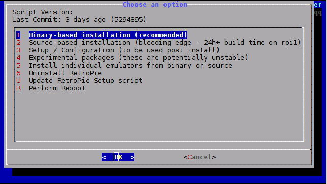
    A new windows will open there u must choose Configuration/Tools and ‚raspiantools‘

    You will enter a new windows with the option to install Pixel Desktop. DO IT!! 🙂

    Wait a few minutes to finish everything and return back to emulationstation. Restart your Raspberry Pi.

    Again in emulationstation, enter the second terminal like we did above.

    now we need to edit the desktop entries for the tft screen, sudo nano /usr/share/X11/xorg.conf.d/99-calibration.conf

    just copy paste everything and save it with ‚ctrl + o‘   and exit with ‚ctrl + x‘

    Section "InputClass" 
    
    Identifier "calibration" 
    
    MatchProduct "ADS7846 Touchscreen" 
    
    Option "Calibration" "160 3723 3896 181" 
    
    Option "SwapAxes" "1" 
    
    EndSection

    and edit also the file sudo nano /usr/share/X11/xorg.conf.d/99-fbturbo.conf

    change the file from:

    Option "fbdev" "/dev/fb0"

    to:

    Option "fbdev" "/dev/fb1"


    Driver Download:

    cd /tmp 
    
    wget http://www.joy-it.net/anleitungen/rpi/tft32b/waveshare32b-overlay.dtb 
    
    sudo cp waveshare32b-overlay.dtb /boot/overlays/waveshare32b.dtbo

    Reboot your Pi, and you should have your tft screen working with touch screen support 🙂 🙂


    Now let’s get to the picki part Frames and Performance:


    Performance:

    Edit the file sudo nano /boot/config.txt

    paste everything at the end of the file:

    arm_freq=1100
     gpu_mem=333
     force_turbo=1
     core_freq=250
     disable_splash=1
     boot_delay=1

    and comment out the three lines for the gpu memory setting:

    #gpu_mem_256=128
     #gpu_mem_512=256
     #gpu_mem_1024=256

    Now we have our Performance set to get the most games running and also to have a stable environment for the os.

    WE ARE NOT RESPONSIBLE FOR ANY OVERCLOCKING DAMAGE!!!


    After our first Versions we realized, that the Design part will take a little bit longer…
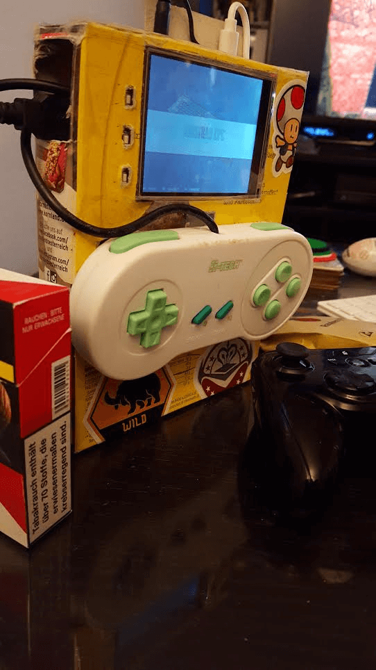
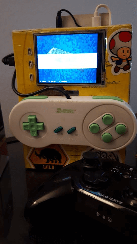
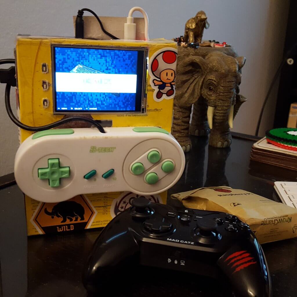
    MKI

    MKII

    Happy New Year 2017 to all our gaming Community and tech Lovers.. Thank you all for the Support!! 🙂 🙂

    Ein von BLOGDOTTV | #GAMES #LIFESTYLE (@blogdottv) gepostetes Foto am

    MKIII


    MKIV Design after 10 Days searching for the right box ^^


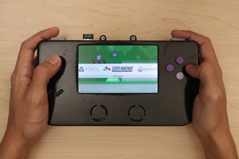
    MKV next Design, 3D Printed from https://www.3dhubs.com/

    we callculated a nice case for 25€ with pick up, so that is pretty ok 🙂

    http://www.thingiverse.com/thing:629873


    Hitting the 60 Frames – comming tommorow

    Setting up the GPIO Buttons  – comming tommorow


    Our old Retropie Tutorials:

    https://www.blogdot.tv/2014/08/17/raspberry-pi-retropie-2014-tutorial-make-gaming-console-100/

    *OUTDATED*

    https://www.blogdot.tv/2014/08/23/retropie-emulationstation-steam-xbmc-raspbian-os-fully-working-files-included/

    *OUTDATED*

  • Geek 3D Prints Super Game Pi, a Fully-Functional Portable Gaming Console!

    Geek 3D Prints Super Game Pi, a Fully-Functional Portable Gaming Console!

    Reading Time: 3 minutes

    3D printing can be used to make many things, including portable gaming consoles, like the Super Game Pi. This DIY game console has 12 buttons, an analog joystick, stereo speakers and a 5-inch HDMI display. This geek used a Raspberry Pi A+ and RetroPie image to enable users to play lots of games across several platforms.

    [mbYTPlayer url=“https://www.youtube.com/watch?v=f_zp42fQ-dQ“ opacity=“.5″ quality=“medium“ ratio=“auto“ isinline=“false“ showcontrols=“false“ realfullscreen=“true“ printurl=“true“ autoplay=“true“ mute=“true“ loop=“true“ addraster=“true“ stopmovieonblur=“false“ gaTrack=“false“]

    [sublimevideo settings=“youtube-id:f_zp42fQ-dQ“ width=“651″ height=“366″]

    Features Components:
    • Raspberry Pi A+
    • True 5” HDMI Display w/ TFP401 Display Driver
    • Analoy joystick + 6 Buttons
    • 66000mAh Lithium Ion Battery
    • Powerboost500 Charger
    • Stereo Audio
    —————————————-­-

    super-game-pi-portable-game-system

    Download 3D Print Case: super-game-pi Source: https://www.youmagine.com/designs/super-game-pi

    Circuit Analysis

    Take a moment to look over the components. The circuit diagram is ment to be used a reference for visualizing wired connections.

    The length of wires, dimension of components, and positions are not exact.

    gaming_circuit-diagram.png

    Wired Connections

    The four main components (Raspberry Pi A+, TFP401 display driver, 2.8W Amplifier and PowerBoost500C) will be powered by the PowerBoost 500C and a 6600mAh Lithium Ion battery via JST cable. To power the circuit on/off, a slide switch is connected to the EN, GND, and Bat pins on the PowerBoost500C.

    The 2.8W Amplifier is connected to GND and +Postive pins on the PowerBoost 500C. A right-angle 3.5mm stereo plug to pigtail cable is wired to the amp and connected to the audio jack on the Pi A+. Two mini metal speakers are wired to the audio output pins on the amp.

    The 5V and GND pins on TFP401 display driver are wired to the 5V and GND pins on the PowerBoost500C. A flat HDMI cable is connnected from the TFP401 to the Raspberry Pi A+.

    The 5″ HDMI display uses a 40-pin FPC extension board to connect the TFP401 display driver to the screen.

    Raspberry Pi GPIO

    Below is a legend of each connection. It includes the pin number, name and connection. The GPIO graphic matches the order of the pins. Use this to reference which buttons connect to the GPIO.

    gaming_pin-legend.png

    How Do I Read This?

    The pin# is the actual number of the pin in series. The numbers go from left to right, top to bottom. The name is the title for a given pin entity. Note the GPIO # does not match the pin number. The connection is the button or wire that needs to be assoicated with the pin.

    The GPIO # will be associated with the Input value in the retrogame.c file.

    In most cases, you should print out the legend (on physical paper) and use it as a cheatsheet while assembling the circuit.

    Button ConnectionsUP        – GPIO 17, Pin 11
    DOWN – GPIO 27, Pin 13
    LEFT    – GPIO 22, Pin 15
    RIGHT  – GPIO 23, Pin 16
    Select  – GPIO 18, Pin 12
    Start    – GPIO 4, Pin 07
    A         – GPIO 24, Pin 18
    B         – GPIO 10, Pin 19
    X         – GPIO 09, Pin 21
    Y         – GPIO 25, Pin 22
    L         – GPIO 11, Pin 23
    R         – GPIO 08, Pin 24
    Color CodesBlack    – Ground
    Red       – DC Power
    Blue      – SDA1, I2C
    Green   – GPIO
    Orange – TX/RX
    Pink       – SPI
    Yellow  – I2C ID EEPROM


    „To make your own Super Game Pi, you’ll have to 3D print the enclosure, hack an SNES controller and solder electronics. You can pick the Raspberry Pi A+ and all the parts to build this project from Adafruit. We’ll need some hand tools and access to a 3D Printer,“ says its creator.

    Source: https://learn.adafruit.com/super-game-pi