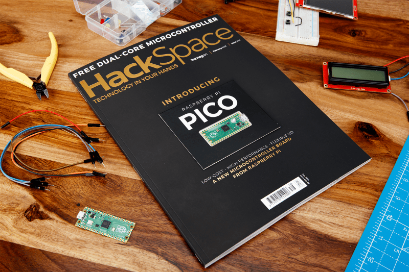
How to add LoRaWAN to Raspberry Pi Pico
Reading Time: 9 minutesArguably the winner of the standards war around wide area networking protocols for the Internet of Things, LoRaWAN is a low-powered, low-bandwidth, and long-range protocol. Intended to connect battery-powered remote sensors back to the internet via a gateway, on a good day, with a reasonable antenna, you might well get 15km of range from an […]