Schlagwort: mega

  • Check out James Bruton’s robotic camera operator

    Check out James Bruton’s robotic camera operator

    Reading Time: 2 minutes

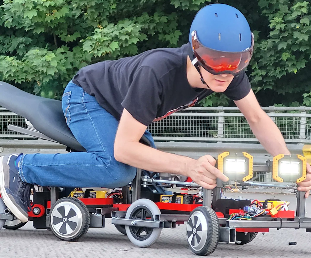
    We’re ages past the time when a YouTuber could get away with sloppy camera work. If someone wants to achieve any level of success making videos today, they need near-professional camera equipment. But even that equipment isn’t enough if it’s still used for static shots. Many makers build sliders and other rigs, but James Bruton skipped those small steps and jumped straight to a versatile robotic camera operator.

    Bruton wanted to capture dynamic videos at any time of day or night without hiring a live-in camera operator and this robot is the result. It can drive around and has complete control over the mounted DSLR camera. It can follow pre-programmed movement patterns, can use tracking to stay focused on Bruton, or a combination of the two to change perspective while staying centered on Bruton. It can also automatically zoom in and out based on motion to ensure that anything interesting is in frame. Bruton can even trigger additional features using foot switches, such as raising a robotic thumbs-up into the frame.

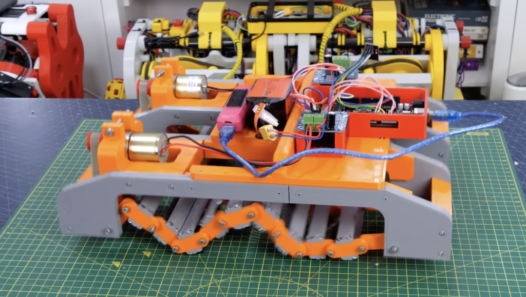
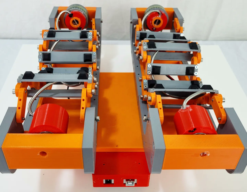
    This robot is quite complex and Bruton’s video focuses on features over hardware details, but he does tell us that the robot has both an Arduino Mega 2560 development board and an NVIDIA Jetson Nano single-board computer. The Arduino handles the low-level control of the motors, while the Jetson does the heavy computer vision processing. The robot’s base contains three motor-driven omniwheels, so it can drive smoothly in any direction. The camera mount pans and tilts, and a servo spins the zoom ring. Bruton 3D-printed most of the robot’s physical parts, with only a handful of aluminum extrusion for the vertical structure. With this robot in his arsenal, we expect Bruton’s videos to be far more dynamic in the future

    The post Check out James Bruton’s robotic camera operator appeared first on Arduino Blog.

    Website: LINK

  • This Tee Eye calculator sculpture tells a story

    This Tee Eye calculator sculpture tells a story

    Reading Time: 2 minutes

    Moore’s Law and the rapid progression of technological development have one very serious downside: e-waste. Because so many electronic devices become obsolete within just a few years, the world ends up with literal mountains of discarded devices that no longer serve any practical purpose. Fortunately, humans value more than practicality. Eddie Farr proved that when he turned an old and broken TI-83 calculator into this interesting Tee Eye sculpture that tells a story.

    If you were in school any time in the last 25 years, then you probably used a TI-83 calculator. For a while, it was the graphing calculator and updated versions are still sold today. A friend of Farr’s found this particular TI-83 while out on a run. It was covered in mud and completely non-functional. Most people would have ignored it or thrown it away, but Farr has vision and wanted to revive the calculator. After days of cleaning, he was able to make it turn on. But it still wasn’t completely functional, as only have the screen worked and several of the input keys were dead.

    Farr’s solution was to repurpose the TI-83 as sculpture that displays poetry. He used an Arduino Mega 2560 and an absurd number of optocouplers to press the TI-83’s buttons. The Arduino sketch takes an input string (like a poem) and pushes the corresponding TI-83 button for each character in sequence. A slight delay between each button press makes the text input slow enough to read. In this way, viewers can watch as poems and stories appear on the TI-83’s screen.

    The rest of Eddie’s work went into the chaotic —yet beautiful — sculpture. The TI-83’s PCB and the Arduino mount to a nice wood plank, with the wires and optocouplers suspended in the air between. It looks almost disorderly, but that fits well with the project.

    The post This Tee Eye calculator sculpture tells a story appeared first on Arduino Blog.

    Website: LINK

  • Binbot 9000 moves to where the trash is

    Binbot 9000 moves to where the trash is

    Reading Time: 2 minutes

    Our modern societies create a lot of garbage, which we can fortunately remove from our homes thanks to local waste management services. But the garbage people won’t come sift through your house for refuse, which forces you to utilize trash bins. Those bins never seem to be nearby when you need them, which is why James Bruton built the Binbot 9000.

    The Binbot 9000 is exactly what it sounds like: a robotic trash can. No longer must the bin remain stationed in some out-of-the-way location. Instead, Binbot 9000 can drive around a home in search of people who need to throw things away.

    Bruton started by placing a standard trash can on a robotic frame built using aluminum extrusion and 3D-printed parts. It has two drive wheels with encoders, which an Arduino Mega 2560 controls. To navigate through the home while avoiding collisions, Bruton added an NVIDIA Jetson Nano single-board computer and a Raspberry Pi Camera. The Jetson runs computer vision software and feeds commands to the Arduino via serial.

    The computer vision software looks for simple targets printed on sheets of paper. The robot rotates until it sees and centers a target in the video frame. It will then drive forward until it reaches the target, rotates 90 degrees, and repeats the process. If it collides with something (ideally someone’s foot), the wheel encodes will detect the stall and the robot will open its lid with a servo. After someone deposits trash and closes the lid, the robot will go back into its target-seeking cycle.

    By placing targets in strategic locations around his home, Bruton gave Binbot 9000 the ability to drive around his home in efficient paths. Whenever he needs to throw something away, he can nudge the robot to stop it and deposit his garbage. It also responds to voice commands, so Bruton can summon it or send it home as needed.

    The post Binbot 9000 moves to where the trash is appeared first on Arduino Blog.

    Website: LINK

  • Fully automated desktop weaving machine controlled by Arduino

    Fully automated desktop weaving machine controlled by Arduino

    Reading Time: 2 minutes

    Automated weaving machines are one of the most important (and underappreciated) advancements to come from the industrial revolution. Prior to their invention, most people only owned a few garments that were woven and maintained by the family. With the introduction of machines able to churn out textiles, affordable clothing suddenly became available. As an expert in the industry, Roger de Meester was able to construct a fully automated weaving machine controlled by Arduino boards.

    Unlike the early weaving machines of the industrial revolution that could only produce patterns inherent to their construction, de Meester’s desktop weaving machine utilizes sophisticated computer control to produce a huge range of patterns on demand. A new pattern can be completely different from the preceding pattern and the machine can even adjust the pattern on-the-fly during the weaving process, meaning it can create rich tapestries.

    This machine is incredibly complex, as it doesn’t rely on any mechanical coupling. That means that every facet of the machine’s operation is adjustable via a stepper motor, DC motor, or servo motor. There are a lot of motors to drive, so de Meester needed multiple Arduino boards: an Arduino Mega 2560 and two Arduino Nanos. The mechanical components are 3D-printed (like the shuttles) or made from aluminum extrusion and wood (like the frame).

    None of our descriptions can give this project justice, so be sure to watch the video to see de Meester’s machine in action.

    The post Fully automated desktop weaving machine controlled by Arduino appeared first on Arduino Blog.

    Website: LINK

  • Wesley Kagan’s PorscheKart project returns with a new Arduino-powered F1 steering wheel

    Wesley Kagan’s PorscheKart project returns with a new Arduino-powered F1 steering wheel

    Reading Time: 2 minutes

    As part of his ongoing PorscheKart project, YouTuber Wesley Kagan wanted a better way to steer his V12 custom-built race car, as the previous wheel was simply a mechanical linkage to the front steering. Instead, this new version would closely mimic the layout and functionality of an actual Formula 1 wheel, complete with all of the buttons, dials, switches, and the central screen.

    The base of the wheel was formed from a laser-cut sheet of aluminum while the surrounding grips were painstakingly 3D-printed out of TPU filament. For the electronics, Kagan decided to use a pair of Arduino Micros, which were split between handling button inputs and driving the display, while an Arduino Mega 2560 gathers sensor data and sends it as a string to the two boards. Because of the limited number of pins, he wired each of the three rotary switches’ output pins to a differently valued resistor, thereby letting the analog input on the Micro know which position is selected by the incoming voltage.

    The final steps of building this upgraded steering included connecting the 3.5” LCD screen to one of the Arduino Micro boards and wiring everything together with the help of a couple harnesses to minimize the mess. However, creating the graphics program proved to be a challenge due to the limited space in ROM for storing all of the draw function calls, which is why Kagan plans on eventually swapping it out for a static image that has the values filled-in. To see more about the project, you can watch his build log video below and read this blog post.

    The post Wesley Kagan’s PorscheKart project returns with a new Arduino-powered F1 steering wheel appeared first on Arduino Blog.

    Website: LINK

  • This strange exoskeleton glove enables VR force feedback

    This strange exoskeleton glove enables VR force feedback

    Reading Time: 2 minutes

    We’re currently seeing something of a technological blitzkrieg as corporations and engineers attempt to solve the problem of tactility in virtual reality (VR). Modern VR headsets provide quite realistic visual and auditory immersion, but that immersion falls apart when users find themselves unable to physically interact with virtual objects. Developed by a team of National Chengchi University researchers, ELAXO is an Arduino-controlled exoskeleton glove that enables complex force feedback for VR applications.

    ELAXO looks unwieldy — it is like an exoskeleton glove made up of 3D-printed struts and joints. In the demonstrated setup, ELAXO mounts to the user’s wrist and has force feedback structures attached to their thumb and first two fingers. Each finger receives four servo motors, four small DC motors, and one larger DC motor. Those motors attach to joints to create on-demand physical resistance to movement.

    For two fingers and a thumb, ELAXO requires a total of 12 servos, 12 small DC motors, and three large DC motors. Each finger also needs an infrared (IR) sensor, for a total of three. In addition, the large DC motors contain encoders that use two wires each. Controlling those takes a lot of I/O pins, which is why the ELAXO team chose an Arduino Mega board for their prototype. It controls the motors through eight dual TB6612FNG drivers.

    The Arduino powers the motors according to what happens in the VR world. For example, if a user tries to touch a stationary object, the motors on that finger might get full power to keep the joints from bending and to provide a feeling of solid resistance. Other actions, like rotating a knob, result in less resistance. By gaining granular control over the resistance of each joint, ELAXO can produce convincing force feedback.

    The post This strange exoskeleton glove enables VR force feedback appeared first on Arduino Blog.

    Website: LINK

  • Increase a robot arm’s payload capacity by relocating its wrist motors

    Increase a robot arm’s payload capacity by relocating its wrist motors

    Reading Time: 2 minutes

    To give an electric car more range, you need a bigger battery pack. But that adds weight, so you need bigger motors and more battery capacity to compensate. This creates a vicious cycle and robot arms are susceptible to a similar problem. A robot arm needs to lift its own weight in addition to whatever it picks up. Bigger motors to increase the payload capacity also increase weight, thereby decreasing the payload capacity. This video from RoTechnic describes how to sidestep that cycle with remote motors.

    RoTechnic’s robot arm has six degrees of freedom (DoF): a rotating base, a shoulder joint, an elbow joint, a rotating wrist joint, a tilting wrist joint, and a rotating end effector. If the robot were a conventional design, all of those joints (except the first two) would require a motor that adds levered weight to lift. The weight of those motors would subtract from the amount that the arm could otherwise lift. But three of this robot’s motors sit on the table nearby so that it doesn’t need to lift them.

    RoTechnic used an Arduino Mega 2560 board to control those motors. Most of the robot’s other parts were 3D-printed. Some of the motors, like for base rotation and the shoulder joint, remain in the conventional location. But three of the motors actuate their joints via fishing lines fed through Bowden tubes. The motors have spools and when those rotate they loosen one line while tightening the other. Each joint has a similar spool, so the fishing lines turn them. The only limitation is that a joint can’t rotate indefinitely, but one can mitigate that by looping the fishing line around each spool many times to provide an equivalent number of revolutions.

    [youtube https://www.youtube.com/watch?v=0hGy4AxUOnk?feature=oembed&w=500&h=281]

    This technique has been in use in the robotics industry for longer than computer control and isn’t groundbreaking. But RoTechnic’s build demonstrates how easy it is for hobbyists to integrate the technique into their robot designs.

    The post Increase a robot arm’s payload capacity by relocating its wrist motors appeared first on Arduino Blog.

    Website: LINK

  • Interactive Halloween costume lets passersby play Wordle

    Interactive Halloween costume lets passersby play Wordle

    Reading Time: 2 minutes

    You’re probably already familiar with the game Wordle — it was a hit in 2021 and then took the world by storm when The New York Times purchased it in 2022. The gameplay is simple to understand, but still challenging. Players have to identify a word through trial and error by making guesses to identify matching letters and letter positions. Ches’ Halloween costume called “Hallo Wordl” lets passersby play a physical version of the game.

    Hallo Wordl’s gameplay is similar to standard Wordle, except that the words are all spooky. Those can include words like “ghost” or “foggy.” There doesn’t seem to be any dictionary checking, so players can enter a string of characters that isn’t a real world. But that isn’t a big deal when this mostly acts as an icebreaker for Halloween parties. Players can enter their guesses using a small 12-button keypad through T9-style typing (though there is no predictive text). That might stop gen-z from playing Hallo Wordl, but it provides a much more compact and affordable interface than a full keyboard.

    The game board displays on two 32×32 RGB LED matrix panels from Adafruit. An Arduino Mega 2560 controls the matrices using Adafruit’s GFX, Matrix Panel, and BusIO libraries. To generate a seed for randomly selecting a word, the Arduino polls one of the analog pins that doesn’t have anything connected and is therefore “floating.” Power comes from a 2200mAh 3s LiPo battery pack, which is good for around four hours of use. The components fit inside of a tombstone-shaped, 3D-printed enclosure that Ches can wear on his chest. 

    Ches already tried Hallo Wordl at a pre-Halloween event and reports that it was a success.

    The post Interactive Halloween costume lets passersby play Wordle appeared first on Arduino Blog.

    Website: LINK

  • This Andor-inspired droid moves like the real B2EMO

    This Andor-inspired droid moves like the real B2EMO

    Reading Time: 2 minutes

    The new Andor TV show, set in the Star Wars universe prior to the events of Rogue One, is already a hit and a big part of that is thanks to the B2EMO droid. Like many of the other droids in the Star Wars franchise, B2EMO manages to be very expressive despite being cold, hard steel. It conveys emotions and expressions through complex movement, which James Bruton recreated when he built his B2EMO-inspired droid.

    B2EMO looks like a conventional rover robot, but it is quite flexible. It can drive in any direction thanks to its omnidirectional wheels and also tilts, leans, and stretches, which makes it seem more like a beloved pet than a soulless robot. The Andor production team actually built a functional B2EMO for filming. Bruton put his own unique spin on the design to create a B2EMO replica that is affordable enough for a hobbyist to tackle.

    An Arduino Mega 2560 board controls all of the robot’s motors and servos. It receives commands through an nRF24L01 radio transceiver module with signals coming from Bruton’s universal robot remote. Most of the robot’s structure is a combination of aluminum extrusion and 3D-printed parts. Four omniwheels driven by DC motors let it move in any direction, while several servo-actuated joints (and even an interesting rack-and-pinion linear expansion system) impart the complex movement. With those, it can lean in any direction and also expand its own wheel base.

    [youtube https://www.youtube.com/watch?v=zpHlCWpQh-I?feature=oembed&w=500&h=281]

    As it stands, this robot moves like B2EMO but doesn’t look much like it. In follow-up videos, Bruton plans to work on the aesthetics and will hopefully end up with something very similar to the onscreen Andor droid.

    The post This Andor-inspired droid moves like the real B2EMO appeared first on Arduino Blog.

    Website: LINK

  • This gorgeous headboard simulates sunrises

    This gorgeous headboard simulates sunrises

    Reading Time: 3 minutes

    The world would be a much better place if everyone could wake according to their own natural circadian rhythm and natural sunlight peeking through their window. But the world doesn’t work like that and many people have to force themselves awake. That’s especially true for people who don’t have conventional work schedules and this gorgeous Artificial Sunrise Headboard gives them a pleasant wakeup call.

    Consider how our ancestors woke up before artificial lighting came along and humanity was still nomadic, because we haven’t evolved much since then. As the sun started to rise, the sky would transition from black to dark blue and then continue to lighten over the course of an hour or two. That provided people with gradual stimulation to ease them from sleep into wakefulness, which stands in stark contrast to the sudden, blaring alarms that are common today. This headboard simulates the gradual sunrise and an integrated personal assistant brews coffee to give sleepers a little extra incentive to get out of bed.

    This headboard is stunning, thanks to the fantastic design and craftsmanship. It partially covers the sleepers’ heads with Adafruit NeoPixel RGB LED lighting, which increases in brightness and changes color over the course of the waking routine. Two Arduino Mega 2560 boards control all of the system’s functions, including the custom personal assistant dubbed PRISMA. An Adafruit MP3 Shield gives PRISMA a voice and a MIKROE SpeakUp 2 Click voice recognition board lets PRISMA understand commands. A DS3231 real-time clock is necessary for accurate timekeeping.

    Details on the construction of the headboard and PRISMA’s functions are available in the Instructables tutorial. But it can respond to a handful of basic commands, such as setting a wake time. At that time, it begins the slow LED animation for the artificial sunrise. It also controls the operation of the coffee maker through a relay module connected to one of the Arduino boards.

    Boards:Mega
    Categories:Arduino

    Website: LINK

  • James Burton is giving legs their snakes back

    James Burton is giving legs their snakes back

    Reading Time: 2 minutes

    James Bruton gave that title to his most recent video as a good-natured jab at Allen Pan’s project about “giving snakes there legs back.” In Pan’s video, he built a robotic exoskeleton to let snakes walk around on motorized legs. But as Bruton noted in his video intro, those legs didn’t look very snakelike. So Bruton created his own robot that walks around on more serpentine limbs.

    This robot’s six limbs each have three degrees of freedom (DoF), all of which are motor-driven. But unlike most robotic limb designs, these use “oblique swivel joint mechanisms.” That mouthful of a term means that each joint rotates on a plane offset at an angle relative to the preceding joint. While that arrangement isn’t suitable for many applications, the kinematics are interesting and the resulting movement does resemble the wriggling of a snake’s body as it slithers along.

    Beefy servo motors rotate the joints and an Arduino Mega 2560 board controls them. The servos don’t allow for continuous rotation, but that wasn’t necessary for this robot’s gait. Power comes from a hobby LiPo battery pack and Bruton pilots the robot using the custom universal remote that makes an appearance in most of his videos. All of the leg segments were 3D-printed and attached to a frame made from a couple pieces of aluminum extrusion.

    While it is easy for the Arduino to control the position of each servo motor, Bruton had to do a lot of work to figure out how to coordinate their movement. He figured out the basics through trial-and-error, but sophisticated control would require trigonometry and the implementation of inverse kinematics. Bruton decided not to bother with those, since he had already accomplished his goal of building robotic legs that look like they would belong to a snake.

    Boards:Mega
    Categories:Arduino

    Website: LINK

  • Auto Xylophone features hand-wound solenoids

    Auto Xylophone features hand-wound solenoids

    Reading Time: 2 minutes

    Arduino TeamSeptember 15th, 2022

    A xylophone is, in addition to being one of only two known English words that start with the letter X, an instrument that most of us haven’t touched since we were toddlers. But xylophones produce a very pleasing sound and their construction is about as simple as an instrument gets. That makes them perfect for DIY projects by those of us who aren’t master craftsmen, and is likely why Rachad El Moutaouaffiq chose the instrument for this Auto Xylophone project.

    As the name implies, this is a xylophone that plays itself. Not only does that let it create beautiful melodies that few of us are capable of hammering out with our clumsy human hands, it can actually exceed the ability of even an accomplished xylophonist. It can strike up to four bars simultaneously, allowing for richer and more complex music than a person could play with only two hands. It works with standard MIDI files and therefore can play a huge range of existing MIDI music or anything new that a musician creates in real time or through other means—such as AI generation that El Moutaouaffiq plans to experiment with. 

    Of course, an Arduino is the key to the Auto Xylophone’s operation. Instead of traditional hammers or mallets, every bar is struck by its own solenoid that drives a small nail. Solenoids rely on electromagnets and El Moutaouaffiq wound all of their coils by hand. Hairless MIDI transfers MIDI signals over serial to an Arduino Mega 2560 board that activates the solenoids through TIP-120 NPN transistors. Those transistors are necessary because the current needed to drive the solenoid electromagnets is too high for the Arduino I/O pins. Power comes from a benchtop power supply and El Moutaouaffiq constructed the xylophone’s frame using MDF.

    At this time, the Auto Xylophone only plays premade MIDI files, but we’re excited to see what kind of AI music generation El Moutaouaffiq comes up with. 

    [youtube https://www.youtube.com/watch?v=kZ-72ajURT8?start=8&feature=oembed&w=500&h=281]

    Website: LINK

  • Building an experimental wave drive tank

    Building an experimental wave drive tank

    Reading Time: 2 minutes

    Arduino TeamSeptember 8th, 2022

    There are many ways to make a thing ambulatory beyond simply slapping on some wheels. James Bruton often experiments with these unique drive mechanisms, whether they are practical or not. In his newest video, he built what he calls a “wave drive” to propel a tank-like robot. This experimental wave drive tank features a 3D-printed body and remote Arduino-based control.

    This drive mechanism works using motion similar to someone doing the worm dance move, which is very much like how flatworms swim through water in nature. For a more technical visualization, imagine a spinning helix projected onto a 2D plane. The result looks like a sine wave, hence the name. The bottom of the wave makes contact with the ground and friction provides grip, letting the mechanism roll forward. That helix visualization also mirrors the physical implementation here, as a screw-shaped drive shaft guides tracks as it spins.

    Bruton 3D-printed almost every physical part of this robot, with the major exception being the helical metal rods. Those rods spin on bearings and an Arduino Mega 2560 controls their 12V DC motors through driver boards. As with more conventional tank tracks, forward or reverse movement occur when both motors spin in the same direction. To rotate the robot, the motors just need to spin in opposite directions. The Arduino can vector motor direction and speed according to throttle and steering inputs from Bruton’s custom remote control.

    As Bruton demonstrates in the video, this wave drive works – but it doesn’t work very well. It is slow, inefficient, difficult to control, and has a hard time overcoming obstacles. That makes sense, since this movement is better suited to ambulation in viscous fluid. Even so, it is great to see Bruton testing the real world practicality of another unconventional drive mechanism.

    [youtube https://www.youtube.com/watch?v=PQqhVzmBNYU?feature=oembed&w=500&h=281]

    Website: LINK

  • Transforming a 3D printer into a four-axis camera slider

    Transforming a 3D printer into a four-axis camera slider

    Reading Time: 2 minutes

    Arduino TeamAugust 19th, 2022

    When creating videos, making smooth, level movements at a constant speed is often a very important requirement, as sudden changes can leave viewers uncomfortable. But rather than purchasing an expensive gimbal-stabilized rig or a commercial motorized camera platform, Instructables user dslrdiy decided to devise their own four-axis system using a repurposed 3D printer with the goal of being able to easily control it through a phone.

    The old 3D printer already contained most of the parts for this build, such as several stepper motors, a controller board, and plenty of miscellaneous hardware. The main axis at the base allows for the primary assembly to move side-to-side with just a single stepper motor, while the other three axes sit on top. These include tilting up and down, rotating around the Z-axis, and rolling.

    Controlling all of these motors is an Arduino Mega 2560 running an instance of RAMPS firmware, which interprets incoming GCODE commands into physical movements. And because it lacks a way to communicate via Bluetooth®, an external ESP32 acts as a remote in order to gather inputs from either its physical buttons or a connected phone. Combined, these devices can be used to set limits and rates for each axis that can, in turn, create amazing timelapse videos with ease.

    [embedded content]

    To see more about this project, you can read dslrdiy’s write-up here.

    Website: LINK

  • This snake robot is large enough to ride upon

    This snake robot is large enough to ride upon

    Reading Time: 2 minutes

    Arduino TeamAugust 13th, 2022

    If a robot is rideable, is it still a robot or is it a vehicle? We would argue that if it rolls on standard automobile-style wheels or even tank tracks, it is a vehicle. But James Bruton’s eight-wheeled robot snake bike is quite clearly something else. This “vehicle” started as a small functional model that everyone would call a robot. Now Bruton has finished the full-size rideable snake robot and it is something to behold.

    The robot consists of four caterpillar-like segments, each with a pair of wheels. Two of the segments have driven wheels, while the other two segments have free wheels. Each segment is able to pivot relative to its neighbor and can also tilt up/down. There are two reasons for the tilt actuation. The first is to compensate for the rider’s weight in order to keep all of the wheels on the ground. The second reason is to handle bumps and uneven terrain, similar to a car’s suspension. The rider sits on a motorcycle seat mounted to the third segment (which is driven), so their weight is roughly centered.

    This unusual setup requires a total of ten motors: four Hoverboard-style hub motors, three steering motors, and three tilt motors. Coordinating the control of that many motors isn’t trivial, which is why Bruton used three Arduino Mega 2560 boards. Each Arduino sends signals through two stepper motor drivers to the steering and tilt motors. Two of the Arduinos control the hub motors through ESCs (electronic speed controllers). Power comes from several big LiPo battery packs and Bruton pilots the robot using the custom universal robot remote that he designed for projects like this.

    Riding the strange snake robot didn’t go quite as well as Bruton had hoped, as the odd steering geometry doesn’t allow for lean and that causes the rider to fall off in turns. But it is still really cool to see in action and we love experimental vehicles!  

    [youtube https://www.youtube.com/watch?v=mnn_Y12RH_8?feature=oembed&w=500&h=281]

    Website: LINK

  • Over-engineered robotic scalp scratcher knows all the moves

    Over-engineered robotic scalp scratcher knows all the moves

    Reading Time: 2 minutes

    Arduino TeamAugust 5th, 2022

    Those cheap wire-arm head massagers are great at giving your scalp a nice, relaxing rub. But they’re handheld implements that force the user to either manipulate the massager themselves or talk a partner into performing the task. David McDaid decided that the experience would be much more pleasant if a robot took care of the hard work, so he built this Stewart platform head massager.

    A Stewart platform is a dexterous manipulator often used with robotic end effectors or for orienting equipment. The standard setup requires six linear actuators, each with universal joints on both ends. The actuators mount between two plates in an arrangement that gives the top plate six degrees of freedom (DoF): pitch, roll, yaw, and linear movement in each of the three spatial axes. A Stewart platform is perfect for this application, because it lets the robot move the head massager in a variety of different ways that mimic manual movement.

    McDaid created his own Stewart platform using an Arduino Mega 2560 board and six AX-12A servo motors in place of the usual linear actuators. The use of servos affects the kinematics to some extent, but not enough for it to be an issue in an application like this that doesn’t require much accuracy. McDaid designed his own custom PCB for this project, which is a shield for the Mega that simplifies the power connection. That power comes from a hobby LiPo battery pack with an XT60 connector. The mechanical parts, including the servo arms, frame, and massager mount, were all designed in Fusion 360 and then 3D-printed.

    The finished robotic head massager is able to perform many different motions, ensuring total relaxation with minimal physical exertion. 

    Website: LINK

  • Arduino-controlled robot solves Rubik’s Cubes in a couple seconds

    Arduino-controlled robot solves Rubik’s Cubes in a couple seconds

    Reading Time: 2 minutes

    Arduino TeamAugust 1st, 2022

    Rubik’s Cubes have been sold in stores for more than 40 years now, but most of us still can’t solve them. Others take the puzzles very seriously, competing in many speed-solving competitions around the world. The world record for the fastest Rubik’s Cube solution is a mere 3.47 seconds, set by China’s Yusheng Du. But this robot created by Redditor iBoot32 puts that record to shame by solving the 3D puzzle in less than two seconds.

    It may not seem like it, but the central square on each side of a Rubik’s Cube remains stationary. By spinning those squares, one can rotate the entire side of the cube. iBoot32’s robot design takes advantage of that fact and has six steppers motors that attach to the central squares on each of the Cube’s six sides. This arrangement gives the robot full manipulation of the Rubik’s cube.

    An Arduino Mega 2560 board controls those six motors through a CNC shield with DRV8825 drivers. The shield only has four motor drivers, so the Arduino has to switch between the motors it can control at any given moment. A nearby PC runs Kociemba’s Optimal Solver software to generate solutions, which then output to the Arduino as a series of rotation commands. iBoot32 can either manually input the Rubik’s Cube’s initial state or use computer vision to automatically input the state into the solver software.

    The exact amount of time it takes to solve a cube depends on its initial state, but iBoot32 says that it usually takes around 1.5 to 2 seconds. 

    Website: LINK

  • This walking machine can mosey in any direction

    This walking machine can mosey in any direction

    Reading Time: 2 minutes

    Arduino TeamJuly 27th, 2022

    Wheeled vehicles are so common because they’re efficient. If a vehicle will drive on a relatively smooth and flat surface, wheels are the most efficient option. But on rough terrain, wheels don’t always cut it. For such terrain, tank tracks and more exotic options often perform better than wheels. Walking machines take that to the extreme, climbing over rough ground in the same way as animals do. But traditional walking machines struggle to turn on the spot without using many motors. To overcome that limitation, James Bruton took inspiration from omni wheels to build a robot that can move in any direction.

    Bruton uses omni wheels in many of his projects. Omni wheels have rollers around their circumference, which lets them roll passively in one direction and actively in another. A vehicle equipped with four omni wheels can move in any direction by spinning the individual wheels in opposing directions. This walking robot utilizes a similar concept. In each mechanism’s active direction, it walks forward. But the feet have freely rotating wheels, which lets each mechanism roll passively to either side. The robot has three of these walking mechanisms in a triangular pattern, so it can move in any direction by controlling which mechanisms are active and which are passive at any given time.

    Each walking mechanism has a single drive motor (a DC motor with a gearbox) that can spin forwards or backwards. Bruton controls the speed and direction of those motors with an Arduino Mega 2560 board via BTS7960 driver modules. The Arduino receives commands from Bruton’s custom remote control through a radio transceiver module. Almost all the robot’s mechanical parts were 3D-printed, with the exception of some aluminum extrusion and fasteners.

    [youtube https://www.youtube.com/watch?v=e1cMjbQnDwY?feature=oembed&w=500&h=281]

    On smooth carpet, the robot walks very well. It can also clear small obstacles, though it won’t be climbing any mountains. But it proved the concept and Bruton is considering building a huge version of this robot that he will be able to ride on. 

    Website: LINK

  • Reviving a classic Sony PS-X75 record player with Arduino

    Reviving a classic Sony PS-X75 record player with Arduino

    Reading Time: 2 minutes

    Arduino TeamJuly 6th, 2022

    In 1979, Sony launched the PS-X75 turntable. It quickly gained popularity thanks to its high-fidelity sound output and ease of use. It was easy to use because it was fully automated–a common feature today, but something that was quite exciting at the time. To perform that automation, the PS-X75 contained an integrated circuit that detected record size, dropped the needle, and so on. But that IC was prone to failure. To revive their Sony PS-X75 turntable, MKB-1 used an Arduino Mega to replace the original circuit.

    Unlike earlier turntable designs, which were often entirely electromechanical, the PS-X75’s IC controls almost all of the turntable’s functions digitally. That means that when the IC fails, the turntable becomes inoperable. Replacement ICs are almost impossible to find and haven’t been manufactured in many years. For most people, this means that the PS-X75 becomes e-waste when that IC bites the dust. But MKB-1 has some reverse-engineering skill and was able to save their PS-X75 by swapping out original IC for an Arduino Mega.

    MKB-1 was able to achieve this impressive feat by carefully studying the original PS-X75 service manual, which included detailed schematics and details on each function’s electrical operation. With this info, they replicated all 42 of the original IC’s connections on an Arduino Mega 2560 development board. They chose the Mega because it had enough I/O pins available to handle all of those connections. Their custom Sketch handles all of the original functionality, from reading button presses to lowering the tone arm. If you own a PS-X75, MKB-1’s detailed Instructables tutorial will walk you through how to perform this retrofit. 

    [youtube https://www.youtube.com/watch?v=31ILr8oTtt4?feature=oembed&w=500&h=281]

    Website: LINK

  • Brenda is classic automata nightmare fuel

    Brenda is classic automata nightmare fuel

    Reading Time: 2 minutes

    Arduino TeamJuly 5th, 2022

    Art is a strange thing. Sometimes its purpose is purely aesthetic. Sometimes it makes a statement. And sometimes it exists to disturb. Kinetic art is no different and some robots fall into this category. Graham Asker’s art elicits pondering on the relationship between humans and robots, as well as the relationships between different robots. But as Brenda, a classical-style automaton, demonstrates, Asker’s art can also induce nightmares.

    Brenda and her companion Brian are strange, bodiless robots designed to mimic the aesthetics of automatons from myth and history. Each robot is a construction of beautiful brass, mechanical joints, linkages, and cables. Servos hidden inside the bases of the robots actuate the various joints, giving Brenda and Brian the ability to emote. Most of their “facial” movement is in their eyes. Lifelike eyeballs look around from within heavy eyelids, while pivoting eyebrows help to convey expressions.

    Arduino boards, also hidden within the robots’ bases, control the servos that actuate the joints. Asker programmed the Sketches with a variety of different servo movements that correspond to facial expressions and eye movements. Brenda even received lips, so she can smile – or frown. Both robots’ bases rotate, so the robots can turn to look at their surroundings. Brenda and Brian do not have any communications hardware and so they can’t interact with each other, but Asker can sync their pre-coded movements to create the illusion that they do.

    Asker, who is a retired engineer with a Master’s degree in fine art, displayed Brenda at London’s Espacio Gallery and on the Walthamstow Art Trail.

    Website: LINK

  • This DIY basketball scoreboard looks and sounds like the real thing

    This DIY basketball scoreboard looks and sounds like the real thing

    Reading Time: 2 minutes

    Arduino TeamJuly 3rd, 2022

    Inspired by his time as a scorekeeper in elementary school, now-high schooler Collin Wentzien wanted to recreate this setup by building a DIY scoreboard several years ago. His idea involved making a bright display composed of several seven-segment displays that could all be controlled by an external device in order to set scores, start/stop the clock, and more.

    The controller sits inside of a small custom box that contains a pair of button matrices, which either increment the score for the home/guest team or provides a keypad that can be used to enter numerical values and set the clock. Below its custom PCB is an Arduino Mega 2560 that handles all of the button inputs, along with a character LCD for showing what has been entered and an nRF24L01+ wireless transceiver for sending new data to the scoreboard.

    Originally, Wentzien had planned on using hundreds of individual LEDs, but due to the resulting wiring complexity, instead opted for a single string of WS2812B LEDs which were not only cheaper, but also allowed for fun animations and colors. Similar to the controller, the scoreboard houses an Arduino Uno as well as an nRF24L01+ in order to receive the commands. Best of all, the it even features a loud horn that can be used to signal the start and end of each quarter.

    To see how Wentzien built this highly interactive project, you can read his write-up here on Hackster.io or watch his video below!

    [youtube https://www.youtube.com/watch?v=zdeKpxZJ_U0?feature=oembed&w=500&h=281]

    Website: LINK

  • This large-format laser cutter was built from scratch for just $700

    This large-format laser cutter was built from scratch for just $700

    Reading Time: 2 minutes

    Arduino TeamJune 30th, 2022

    When stuck between a cheaper yet small laser cutter and splurging on a much larger one, Owen Schafer decided instead to just build one himself. The project started with Schafer sourcing a 40W CO2 laser, which differs from a diode laser in that it uses gas heated with 16,000 volts to produce a very powerful beam of light. This had the added side effect of needing a water-cooling system since the tube tends to generate ample amounts of heat.

    Once the laser and the necessary reflectors had been sourced, Schafer purchased aluminum extrusions and attached them with corner connectors. The head moves with the help of a gantry, wherein the X-axis slides along the Y-axis, and both are driven by NEMA17 stepper motors and a timing belt. For some added safety, he created a basic enclosure out of plywood just in case something went wrong internally.

    Each stepper motor is driven by an A4988 driver module, and all of them are controlled by an Arduino Mega 2560 loaded with the Marlin-based Marlaser laser cutter firmware. He even included a few LEDs strips within the enclosure that aid visibility and a simple ventilation system for fume extraction.

    After generating some toolpaths using Inkscape, the laser was finally able to cut nearly anything out of materials ranging from plastic to plywood. You can watch more about how Schafer brought this inexpensive laser cutter to life in the video below!

    [youtube https://www.youtube.com/watch?v=QtEF6c1t2tM?feature=oembed&w=500&h=281]

    Website: LINK