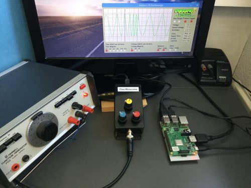
Schlagwort: arduino

  • Thomas the Tank Engine turned into a karaoke robot

    Thomas the Tank Engine turned into a karaoke robot

    Reading Time: < 1 minute

    Thomas the Tank Engine turned into a karaoke robot

    Arduino TeamAugust 13th, 2018

    When Hunter Irving spotted a knockoff Thomas the Tank Engine toy at a thrift store, he simply had to buy it, telling himself that he’d turn it into an animatronic contraption at some point. While these kind of promises often go unfulfilled, Irving converted it into an egg-shaped, karaoke-singing robot, with a mouth and eyes that move along with music.

    The body of this new robotic device is designed in Blender and 3D-printed, while the mechanicals inside are actuated with a servo. Control is handled by an Arduino, which responds to MIDI signals from a speech synthesizer, used to produce its eerie electronic voice. 

    [youtube https://www.youtube.com/watch?v=IbHfiO7Sy8U?feature=oembed&w=500&h=281]

    Website: LINK

  • Electric-powered fan rocket takes off and lands(?) vertically

    Electric-powered fan rocket takes off and lands(?) vertically

    Reading Time: 2 minutes

    Electric-powered fan rocket takes off and lands(?) vertically

    Arduino TeamAugust 13th, 2018

    Does a rocket need to use a certain type of fuel, or even be capable of spaceflight? While James Bruton’s build might not fit everyone’s definition of this type of craft because of its electric ducted fan (EDF) propulsion, it does face the same major challenge of controlling a tall pipe-like structure from thrust coming from the tail. It’s meant to both take off and land in a vertical orientation as well, something inconceivable in traditional rockets until very recently.

    For control, Bruton uses an Arduino Mega inside the main fuselage of the craft, which regulates the speed of the three EDFs. It also turns two of these fans with a servo and linkage system in order to compensate for unwanted roll. A second Arduino and an IMU are embedded in the nose cone, which passes data to the Mega board via a serial connection. 

    The build and early tests can be seen in the video below, and a full test is planned for the future alongside Ivan Miranda, who has been working on his own version.

    [youtube https://www.youtube.com/watch?v=ZCzXICeH7hY?feature=oembed&w=500&h=281]

    Website: LINK

  • Check the weather on this Arduino-controlled split-flap display

    Check the weather on this Arduino-controlled split-flap display

    Reading Time: < 1 minute

    Check the weather on this Arduino-controlled split-flap display

    Arduino TeamAugust 9th, 2018

    Split-flap displays show information using characters changed by an electric motor. While they’ve largely been replaced by more modern means, hobbyists like “gabbapeople” have been keeping this this technique alive, in this case as a four-character IoT weather display.

    The device is built using laser-cut plexiglass, and uses four individual servos to actuate the character flaps. Control is accomplished using an Arduino Mega programmed in the XOD visual programming environment, along with the requisite driver modules. Weather data is pulled from the AccuWeather API. 

    You can see it flapping away in the video below, displaying the weather in abbreviations such as “ICLO” for intermittent clouds, as well as the temperature in degrees Celsius.

    [youtube https://www.youtube.com/watch?v=UUt0KVzSsMc?feature=oembed&w=500&h=281]

    Website: LINK

  • Automate motor winding with Arduino

    Automate motor winding with Arduino

    Reading Time: 2 minutes

    Automate motor winding with Arduino

    Arduino TeamAugust 7th, 2018

    When you want to make a mobile robot, DC motors can be a great choice. We normally accept that they can be purchased for a few dollars each, but what if you want to make your own?

    In order to assist with the winding process for a self-built—or at least self-wound—motor, Mr. Innovative created an… innovative fixture with two stepper motors and an Arduino Nano for control. 

    The bare motor armature is held in a vertical orientation by one stepper, while the other winds wire using a hollow 3D-printed feeder mechanism. User interface consists of an OLED screen and buttons that let you select the number of windings and another to advance the armature to the next coil location. 

    Arduino code and electrical drawings can be found here, and 3D-printed parts are available on Thingiverse.

    [youtube https://www.youtube.com/watch?v=05jpsSEF_Qs?feature=oembed&w=500&h=281]

    Website: LINK

  • Feed Barbie with the J’ai faim! mechatronic game

    Feed Barbie with the J’ai faim! mechatronic game

    Reading Time: < 1 minute

    Feed Barbie with the J’ai faim! mechatronic game

    Arduino TeamAugust 7th, 2018

    According to this project’s write-up, while some struggle to get enough nourishment, those in more developed countries often aspire to consume too little food. As an apparent commentary on this situation, Niklas Roy and Kati Hyyppä have created a mechatronic game called J’ai faim!, French for “I’m hungry!”

    In this Arduino-controlled game, participants rotate a Barbie head to point her comically over-sized tongue over a piece of sushi lit up by an LED. When in position, the player fires her solenoid-actuated tongue using the joystick, and if the correct sushi is eaten the score progresses from “starving” to “well fed.” 

    You can see the game—reminiscent of a very strange version of whack-a-mole—in the video below.

    [youtube https://www.youtube.com/watch?v=KKAWjVZ9pTI?feature=oembed&w=500&h=281]

    Website: LINK

  • Generating waves with Arduino

    Generating waves with Arduino

    Reading Time: < 1 minute

    Generating waves with Arduino

    Arduino TeamAugust 6th, 2018

    Need a wave generator to test out your latest boat, barge, or submarine design, but can’t quite afford one? If so, then you might consider Subham Bhatt’s DIY tank that he was able to construct for around $1,200 USD. 

    Bhatt’s device features a pair of stepper motors and lead screws that push a stainless steel paddle through the water, producing waves formed to his precise specifications. An Arduino Mega is used for control, along with a single stepper driver to power both motors. 

    User interface is provided through the Arduino IDE’s serial interface, set up to take commands via a simple text-based menu system. 

    [youtube https://www.youtube.com/watch?v=wovaaC5p6dg?feature=oembed&w=500&h=281]

    Website: LINK

  • Develophead takes (some) of the work out of film photography

    Develophead takes (some) of the work out of film photography

    Reading Time: 2 minutes

    Develophead takes (some) of the work out of film photography

    Arduino TeamAugust 6th, 2018

    Today, if you take a photograph, more than likely it’s digital. This presents many advantages over its film counterpart, but many serious photographers still use the format in order to produce just the right effect. Pablo Zárate is one such photographer, and combined this passion with Arduino and 3D printing knowledge to produce the “Develophead.”

    Develophead is meant as an augmentation to AP brand developing tanks, adding an automatic agitation function. This previously had to be done by hand, including 16 minutes of manipulation in the case of C41 rolls. 

    Develophead is built on Arduino Nano and uses a 5-volt power source. It’s a cap that fits onto the top of a development tank, inserting an agitation rod into the hole that chemicals are poured into and out of. Turn the cap on and the rod begins to turn the film reel back and forth. A knob on the top of the cap lets you adjust the speed/intensity of the agitation.

    As of now, this labor-saving device is meant for AP Classic development tanks, but  Zárate has released the plans on GitHub and hopes others will help expand on this concept.

    [youtube https://www.youtube.com/watch?v=VPRG-3OeSoE?feature=oembed&w=500&h=281]

    Website: LINK

  • Notable Board Books are an Arduino-powered way to enjoy music

    Notable Board Books are an Arduino-powered way to enjoy music

    Reading Time: < 1 minute

    Notable Board Books are an Arduino-powered way to enjoy music

    Arduino TeamAugust 6th, 2018

    Annelle Rigsby found that her mother, who suffers from Alzheimer’s, is delighted to hear familiar songs. While Annelle can’t always be there to help her enjoy music, she and her husband Mike came up with what they call the Notable Board Book that automatically plays tunes.

    The book itself is well laid-out, with song text and familiar photos printed on the pages. Electronics for the book are in a prototype state using an Arduino Uno and an Adafruit Sound Board to store and replay the audio bits.

    Page detection is handled by an array of photocells, and it is meant to turn on automatically when picked up via a series of tilt switches. When a switch is triggered, a relay can then hold the book on until the song that is playing is done, or for a predetermined amount of time.

    [youtube https://www.youtube.com/watch?v=7jSBl_UZE-c?feature=oembed&w=500&h=281]

    [youtube https://www.youtube.com/watch?v=07F2prjPebc?feature=oembed&w=500&h=281]

    [youtube https://www.youtube.com/watch?v=xtVReDjoA2M?feature=oembed&w=500&h=281]

    Website: LINK

  • A time-telling web powered by Arduino

    A time-telling web powered by Arduino

    Reading Time: < 1 minute

    A time-telling web powered by Arduino

    Arduino TeamAugust 2nd, 2018

    Flament bulbs, commonly known as Edison bulbs, contain a variety of interesting LED lights. So interesting, in fact, that maker Andy Pugh decided to take these individual components up and turn them into a 7-segment display clock.

    While making a clock isn’t an uncommon hacker pursuit, this Arduino-controlled device uses a series of wires to both power and support the clock’s four digits from a bent brass frame. This gives it a decidedly web-like appearance, so much so that Pugh notes it’s reminiscent of the cobweb writing in the book Charlotte’s Web. 

    The clock also features the ability to sync the time via radio signals, though this functionality appears to still be in the experimental phase. 

    Code for the build can be found here, and you can see it cycling through numbers in the video below.

    [youtube https://www.youtube.com/watch?v=w8X2Ao_UzRM?feature=oembed&w=500&h=281]

    Website: LINK

  • Ingenious marble clock runs on Arduino

    Ingenious marble clock runs on Arduino

    Reading Time: 2 minutes

    Ingenious marble clock runs on Arduino

    Arduino TeamAugust 1st, 2018

    Arduino boards and custom clock builds seem to be a great match, as illustrated by Görkem Bozkurt’s recent project. 

    His 3D-printed marble clock uses a stepper-driven gear mechanism to lift 11mm steel spheres to the device’s top chute. The spheres then roll down to a five-minute rail, which empties when filled and transfers a single marble to another minute rail, graduated in five-minute increments up to 60. This then fills the hour rail in a similar process, letting you tell the time of day, or simply be mesmerized by its movement.

    The main gear mechanism is powered by a small stepper motor, controlled by an Arduino Uno for timekeeping.

    If you’d like to build your own, code is available on Bozkurt’s write-up, as well as the needed print files.

    [embedded content]

    Website: LINK

  • Light painting rig is a masterpiece of artistic hardware hacking

    Light painting rig is a masterpiece of artistic hardware hacking

    Reading Time: 2 minutes

    Light painting rig is a masterpiece of artistic hardware hacking

    Arduino TeamJuly 30th, 2018

    Light painting is an art form where dark areas are selectively lit to form interesting effects. While normally a manual operation, Josh Sheldon has come up with a rig to automate and enhance the process. The results are nothing short of spectacular, producing not static images, but astonishing animated light displays.

    His device resembles a 3D printer made out of aluminum extrusion. X,Y, and Z axes are controlled by a series of stepper motors, but it uses a point of controlled light instead of melted plastic to form shapes. 

    Light animations are set up in Blender, and a hardware and software toolchain including Processing, an Arduino Mega, and a Dragonframe module are implemented for control.

    Check out the whole story in the video below, or see code/build documentation are available on GitHub.

    [youtube https://www.youtube.com/watch?v=O1bY66X1JKA?feature=oembed&w=500&h=281]

    Website: LINK

  • Ceiling-mounted cable robot with Arduino Mega

    Ceiling-mounted cable robot with Arduino Mega

    Reading Time: 2 minutes

    Ceiling-mounted cable robot with Arduino Mega

    Arduino TeamJuly 30th, 2018

    Cable-based robots are a common sight at sporting events as remote camera operators, but what about one for your living room? As spotted on Reddit, Nathaniel Nifong decided there was no reason not to have one of these devices, and made his own personal Skycam-like robot.

    The system uses four servo motors to wind cables attached to the ceiling around 3D-printed wheels, and can be controlled using a smartphone via Bluetooth and an Arduino Mega. 

    The prototype—constructed using cardboard and what appears to be LEGO components—is seen moving around Nifong’s dwelling in the videos below, and the eventual goal is to let it move items around using a servo gripper assembly.

    This is the first wireless movement demonstration of a robot I’m building. It’s based on parts from an XYZ 6-DOF robotic arm.

    The Bluetooth control is done by using Nordic toolbox to send commands to a an MDBT40 Bluetooth module that was reprogrammed with an ST-Link V2. The module forwards the command to the Arduino.

    Commands are to move 10 cm in any direction. It calculates what the change in rope lengths would be to achieve the new position.

    [youtube https://www.youtube.com/watch?v=bum5dCi5UIg?feature=oembed&w=500&h=281]

    [youtube https://www.youtube.com/watch?v=Py4l7_BlmFs?feature=oembed&w=500&h=375]

    Website: LINK

  • Stop motion short filmed with the help of Arduino

    Stop motion short filmed with the help of Arduino

    Reading Time: < 1 minute

    Stop motion short filmed with the help of Arduino

    Arduino TeamJuly 30th, 2018

    One can imagine that making a stop motion animation film is a lot of work, but if you’ve ever wondered what one involves, James Wilkinson decided to document the process of making Billy Whiskers: The Mystery of the Misplaced Trowel. 

    The main character of this film is a mystery-solving feline, who is animated with the help of five servos that control mouth movements under Arduino control.

    In order to get shots that move properly, Wilkinson also came up with his own motion capture rig, moved by a number of stepper motors via an Arduino Mega. His documentation is certainly worth checking out if you’re interested in animatronics or advanced filming techniques, and you can see a trailer for the film below.

    [embedded content]

    Website: LINK

  • Single-handed smartwatch text entry with WrisText

    Single-handed smartwatch text entry with WrisText

    Reading Time: 2 minutes

    Single-handed smartwatch text entry with WrisText

    Arduino TeamJuly 26th, 2018

    Smartwatches can keep us informed of incoming information at a glance, but responding still takes the use of another hand, potentially occupied by other tasks. Researchers at Dartmouth College are trying to change that with their new WrisText system.

    The device divides the outside of a Ticwatch 2 into six sections of letters, selected by the movement of one’s wrist. As letters are chosen, possible words are displayed on the screen, which are then selected automatically, or by rubbing and tapping gestures between one’s finger and thumb. 

    The prototype employs an Arduino DUE to pass information to a computer, along with proximity and piezo sensors to detect hand and finger movements. 

    We present WrisText – a one-handed text entry technique for smartwatches using the joystick-like motion of the wrist. A user enters text by whirling the wrist of the watch hand, towards six directions which each represent a key in a circular keyboard, and where the letters are distributed in an alphabetical order. The design of WrisText was an iterative process, where we first conducted a study to investigate optimal key size, and found that keys needed to be 55o or wider to achieve over 90% striking accuracy. We then computed an optimal keyboard layout, considering a joint optimization problem of striking accuracy, striking comfort, word disambiguation. We evaluated the performance of WrisText through a five-day study with 10 participants in two text entry scenarios: hand-up and hand- down. On average, participants achieved a text entry speed of 9.9 WPM across all sessions, and were able to type as fast as 15.2 WPM by the end of the last day.

    More information can be found in the project’s research paper, or you can see it demonstrated in the video below.

    Website: LINK

  • DolphinView headset lets you see the world like Flipper!

    DolphinView headset lets you see the world like Flipper!

    Reading Time: 2 minutes

    DolphinView headset lets you see the world like Flipper!

    Arduino TeamJuly 26th, 2018

    Dolphins are not only amazing swimmers and extremely intelligent, but can also navigate their surroundings using echolocation. While extremely useful in murky water, Andrew Thaler decided to make a device that would enable him to observe his (normally dry) environment with a similar distance-indicating audio setup.

    While he first considered using an ultrasonic sensor, he eventually settled on LiDAR for its increased range, and uses an Arduino to translate distance into a series of audio clicks. Sound is transferred to Thaler through bone conduction speakers, mimicking the way dolphins hear without external ears. 

    He notes that while using the “DolphinView” headset is initially disorienting, he was eventually able correlate his surroundings with the system’s audio feedback. Arduino code and parts list is available on GitHub, and the mechanical frame design can be found on Thingiverse if you’d like to build your own!

    Website: LINK

  • Two CD-ROM drives combined into fledging drawbot

    Two CD-ROM drives combined into fledging drawbot

    Reading Time: < 1 minute

    Two CD-ROM drives combined into fledging drawbot

    Arduino TeamJuly 26th, 2018

    Even if you don’t have access to fancy tools like a 3D printer or CNC router, that doesn’t mean you can’t make something interesting. James, using only a “hot glue gun, some scissors, and a screwdriver,” was able to construct a rudimentary drawing robot that marks paper with a sharpie.

    Two CD drives were creatively modified to form X, Y, and Z axes, letting him lower his writing instrument and draw. An Arduino Uno along with an Adafruit Motor Shield forms the controls for the device, and the structure is built out of LEGO bricks. 

    As of now it’s described as more of an “Etch A Sketch type thing,” but it looks like a great starting point for more advanced drawbots in the future! Code for the build is available on GitHub.

    [embedded content]

    Website: LINK

  • Ping pong ball bounces forever under Arduino control

    Ping pong ball bounces forever under Arduino control

    Reading Time: < 1 minute

    Ping pong ball bounces forever under Arduino control

    Arduino TeamJuly 25th, 2018

    As spotted on Reddit, maker “tkuhn” of Electron Dust decided to create a machine “with the sole goal of keeping a ping pong ball bouncing for as long as possible.” 

    To accomplish this, he turned to audio feedback using the time difference between when four electret microphones sense the sound of the bouncing ball. Audio processing is accomplished with the help of a simple flip-flop circuit, while an Arduino Nano is used to reset it after each cycle.

    Data is then passed along to an Arduino Uno, which employs four steppers motors/drivers and a linkage system to keep the ball in play. This impressive setup can be seen in the video below, and code is available on GitHub.

    [youtube https://www.youtube.com/watch?v=0WiGiJk03Q8?feature=oembed&w=500&h=281]

    Website: LINK

  • Add fading light effects to the buttons on your arcade controller

    Add fading light effects to the buttons on your arcade controller

    Reading Time: < 1 minute

    Add fading light effects to the buttons on your arcade controller

    Arduino TeamJuly 25th, 2018

    Making a custom arcade cabinet has become something of a rite of passage for aspiring hackers. As seen here, maker Rodrigo decided to add an extra bit of “flair” to his build (Portuguese), with buttons that light up under Arduino power. 

    As demonstrated in the video below, the button lights slowly fade out after being pressed, and he’s created a pair of these light-up control boxes, one featuring blue buttons and the other red.

    Notably, he’s using a separate controller to pass signals to his setup, leaving each Arduino free to control the lighting. Code for the project can be found on GitHub if you’d like to try something similar yourself.

    [youtube https://www.youtube.com/watch?v=pr0fkC3hq5E?feature=oembed&w=500&h=281]

    Website: LINK

  • Arduino-Controlled Signal Attenuation

    Arduino-Controlled Signal Attenuation

    Reading Time: 2 minutes

    Arduino-Controlled Signal Attenuation

    Arduino TeamJuly 24th, 2018

    There are many ways to modify analog and digital electrical signals, but things get a bit more complicated—or at least specialized—when working with coaxial signal transmission. To this end, Kerry D. Wong found an unused attenuator evaluation board in his “miscellaneous PCB bin,” and decided to give it a new life using an Arduino.

    The attenuator functions through a set of switches to set power dissipation from 0 to 31.5 dB, but it can use a serial interface for this function as well. In his new setup, the Arduino provides the needed control signal, via a user interface consisting of an encoder and LCD display.

    The fact that it’s now programmable would also open up automated testing possibilities. More on this project is seen in the video below, with the Arduino configuration showing up at around 10:00.

    [youtube https://www.youtube.com/watch?v=6-pVbwjH5es?feature=oembed&w=500&h=281]

    Website: LINK

  • Ramp up programmable LED troubleshooting with the BlinkBox

    Ramp up programmable LED troubleshooting with the BlinkBox

    Reading Time: < 1 minute

    Ramp up programmable LED troubleshooting with the BlinkBox

    Arduino TeamJuly 23rd, 2018

    Programmable LEDs are amazing pieces of hardware, allowing hackers to add a rainbow of colors to projects at reasonable prices. Troubleshooting these devices, however, can be a pain, so Devon Bray developed the “BlinkBox” to help with this task.

    The resulting Arduino-based tester can work with multiple types of LEDs, and is able to cycle through each individual LED module in a string, and change the animation pattern as needed. He had previously done this kind of testing on a breadboard, but his new iteration is much more permanent and professional looking. 

    You can find CAD and code for it on GitHub if you’d like to build your own!

    [youtube https://www.youtube.com/watch?v=rg_kiPnU8oM?feature=oembed&w=500&h=281]

    Website: LINK

  • Smart hydroponic assembly made with Arduino Mega

    Smart hydroponic assembly made with Arduino Mega

    Reading Time: 2 minutes

    Smart hydroponic assembly made with Arduino Mega

    Arduino TeamJuly 23rd, 2018

    If you love electronics as well as plants, what better way to combine the two than with a smart hydroponic system? Students at the Juan de Lanuza School decided to do just that, creating a portable hydroponic assembly that’s automatically controlled with the help of an Arduino Mega.

    The system uses six lengths of PVC pipe to house plants and pass a nutrient rich liquid solution through their roots. The control assembly measures elements such as temperature, humidity, and pH, then adjusts the lighting, water pump, and nutrient feeder to accommodate for conditions. 

    The device transmits data to ThinkSpeak for human monitoring, and also features a smartphone app for visualization. Build details are available here in English, or you can see a video of the setup in Spanish below.

    [youtube https://www.youtube.com/watch?v=FWkw4pRXUVg?feature=oembed&w=500&h=281]

    Website: LINK

  • Build an oscilloscope using Raspberry Pi and Arduino

    Build an oscilloscope using Raspberry Pi and Arduino

    Reading Time: 8 minutes

    In this tutorial from The MagPi issue 71Mike Cook takes us through the process of building an oscilloscope using a Raspberry Pi and an Arduino. Get your copy of The MagPi in stores now, or download it as a free PDF here.

    The oscilloscope is on the wish list of anyone starting out with electronics. Your author used to tell his students that it was your eyes, making electricity visible. Unfortunately, they are quite expensive: from a few hundred pounds to up to £5000 and beyond. However, by using an Arduino and some software on the Raspberry Pi, you can make a passable beginner’s oscilloscope.

    Raspberry Pi Arduino oscilloscope magPi 71

    Last September, in The MagPi #61, there was an article outlining the way the Raspberry Pi and the Arduino could be used together. We at the Bakery have been doing this for some time: we first had a major project in the Raspberry Pi Projects books by Andrew Robinson and Mike Cook. The big advantage of the Arduino from a signal processing point of view is that there is minimal interruption from the operating system and you can gather data at a constant uninterrupted rate. This is just what we need for making an oscilloscope. The idea is that the Arduino gathers a whole heap of voltage samples as fast as it can and stores it in memory. It then transfers that memory to the Raspberry Pi, again as fast as possible. The Pi plots the data and displays it, then the software allows measurements to be made on the samples.

    So you can measure the time and voltage difference, known as a delta, between any two points on the samples. You can even display the frequency that the ‘time delta’ corresponds to by taking its reciprocal. These are features found in expensive oscilloscopes. We have also built in a trigger function; this is to synchronise the onset of the rapid data gathering with the occurrence of a positive transition on the input signal through a specified voltage. The result is that regular waveforms can look stable on the display.

    The hardware

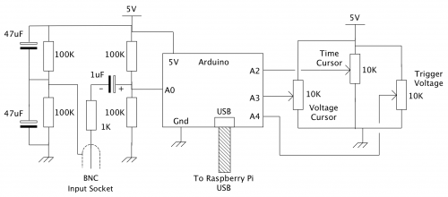
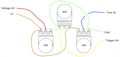
    The schematic of the Arduino data acquisition module is shown in Figure 1.

    Raspberry Pi Arduino oscilloscope magPi 71

    Figure 1: Schematic of the Arduino acquisition module

    You will notice that it is quite simple. It consists of three potentiometers for the oscilloscope’s controls and an AC coupled biased voltage input.

    The capacitor ensures that no DC components from the input get through and gives a modicum of protection against overvoltage. The reference voltage, or ground, is similarly biased as +2.5V above the Pi’s ground level.

    The use of a BNC socket for the input ensures that you can use this with proper oscilloscope probe leads; these normally have an X10 switchable attenuator fitted, thus allowing voltages of +/- 25V to be measured. Full construction details can be found in the numbered steps.

    Raspberry Pi Arduino oscilloscope magPi 71

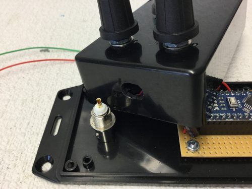
    The BNC socket has a flat on each side of the thread to prevent it rotating with the twisting force it will be subjected to upon connecting any probe. We did this by first drilling an 8mm hole for the flats and then enlarging the hole with a circular file on each side to allow it to fit. An 8×12mm hole was filed opposite the USB connecter to allow access.

    Arduino software

    The software, or sketch, you need to put into the Arduino is shown in the Gather_A0.ino listing, and is quite simple. Normally an Arduino of this type will take samples at a rate of 10 000 per second — or as we say, a 10k sample rate. This is not too good for an oscilloscope, but we can increase this sample rate by speeding up the A/D converter’s clock speed from the default rate. It does not appear to affect the reading accuracy too much. By making this change, we can speed up the sample rate to 58k. This is much better and allows useful measurements to be made in the audio range.

    Raspberry Pi Arduino oscilloscope magPi 71

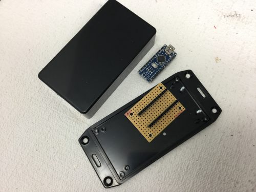
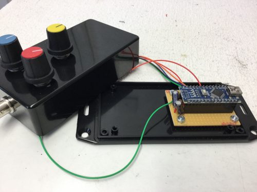
    We used an Arduino Nano and soldered the header pins to it. Then we took a 14 hole by 19 strips piece of stripboard and drilled some holes to fix it to the base of the box. You might want to make this longer than 19 strips if you are not using surface-mount resistors on the underside. Fit header sockets to the stripboard and break the tracks on the underside between the two rows.

    So, first, the trigger function is optionally called and then the samples are gathered in and sent to the Pi. The trigger function has a time-out that means it will trigger anyway after one second, whether it sees a transition on the input signal or not. Then the three pots are measured and also sent to the Pi. Note here that the samples are ten bits wide and so have to be sent as two bytes that get joined together again in the Pi’s software.

    Also note the use of the double read for the pots, with a bit of code between each. This ensures a more stable reading, as the input capacitor of the Arduino’s sample and hold circuit needs time to charge up, and it has less time than normal to do this due to the speeding up of the D/A. It does not affect the waveform samples too much, as in most waveforms one sample voltage is close to the previous one.

    Raspberry Pi Arduino oscilloscope magPi 71

    We then drilled three holes for the pots, and added the small slots for the anti-rotation lugs. Then we fitted the pots and wired them up using the diagram above. This is the view from inside the lid of the box; if you’re worried about touching the side of the box with your soldering iron, consider soldering them before attaching them to the box.

    At the end of the transfer, the Arduino sits in a loop waiting for an acknowledge byte from the Pi so it can start again. This acknowledge byte also carries the information as to whether or not to use a trigger on the next sample.

    Raspberry Pi Arduino oscilloscope magPi 71

    Add the resistors and capacitors to the stripboard and wire up the BNC socket. Solder this up before mounting, otherwise you will melt the plastic. Remember to thread the central wire through the ground washer, crinkle washer, and nut before soldering it. Add labels Trigger, Time, and Volts to the knobs.

    Finally, before each buffer full of data is gathered, pin 13 on the board is lit, and turned off after. This is so that we could time the process on a commercial oscilloscope to find the sample rate — something you will not have to do if you use the recommended AVR-type Arduinos running at 16MHz.

    Pi software

    The software for the Raspberry Pi is written in Python 3 and used the Pygame framework. It proved to be a lot more tricky to write than we first imagined, and is shown in the Scope.py listing. Python 3 uses Unicode characters by default, and allowed us to display the delta (Δ) and mu (μ) Greek characters for the difference and the time. The code first sets up the non-display part of the window; this is only drawn once, and then parts of it are updated when necessary. Depending on what type of Arduino you have, it can show up as a different USB port; we found that ours showed up as one of two ports. Comment out which one is not applicable when defining the sampleInput variable at the start of the listing.

    Finally, we cobbled together a 168×78 pixel logo for the top-left corner, using a piece of clip art and fashioning the word ‘Oscilloscope’ from an outlined version of the Cooper Black font. We called it PyLogo.png and placed it in an images folder next to the Python code.

    Using the oscilloscope

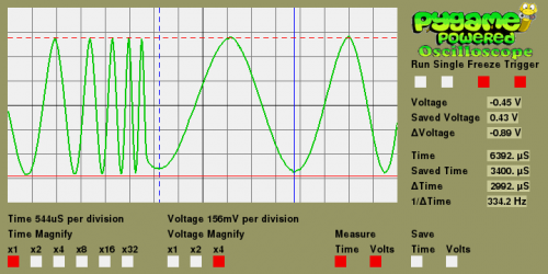
    The oscilloscope samples at 58 kHz, which in theory means you can measure waveforms at 29 kHz. But that only gives you two samples per cycle, and as the samples can be anywhere on the waveform, they do not look very good. As a rough guide, you need at least ten points on a waveform to make it look like a waveform, so that gives a top practical frequency of 5.8 kHz. However, by using the Time Magnify options along with the Freeze function, you can measure much higher frequencies. The time and voltage cursor lines let you find out the values on any point of the waveform, and by clicking the Save functions, the current cursor is replaced by a dotted line that is fixed, and measurements can be made relative to that. The oscilloscope in action can be seen in Figure 2.

    Raspberry Pi Arduino oscilloscope magPi 71

    Figure 2: Taking measurements on a swept signal

    Note that pressing the S key on the keyboard produces a screen dump of the display.

    Taking it further

    There are lots of ways you can take this project further. A simple upgrade would involve you having a second data buffer to allow you to display a saved waveform to compare against the current live one. You could also add a lower-speed acquisition mode to see slower waveforms. You can go the other way and use a faster Arduino so you can see the higher frequencies. This oscilloscope is AC coupled; you could add a DC coupling option with a switch potential divider and amplifier to the front end to extend the range of voltages you can measure. All these improvements, however, will need changes to the software to allow the measuring to take place on these wider-range parameters.

    Finish the project

    For the complete project code, download the free PDF of The MagPi issue 71, available on The MagPi website.

    Website: LINK