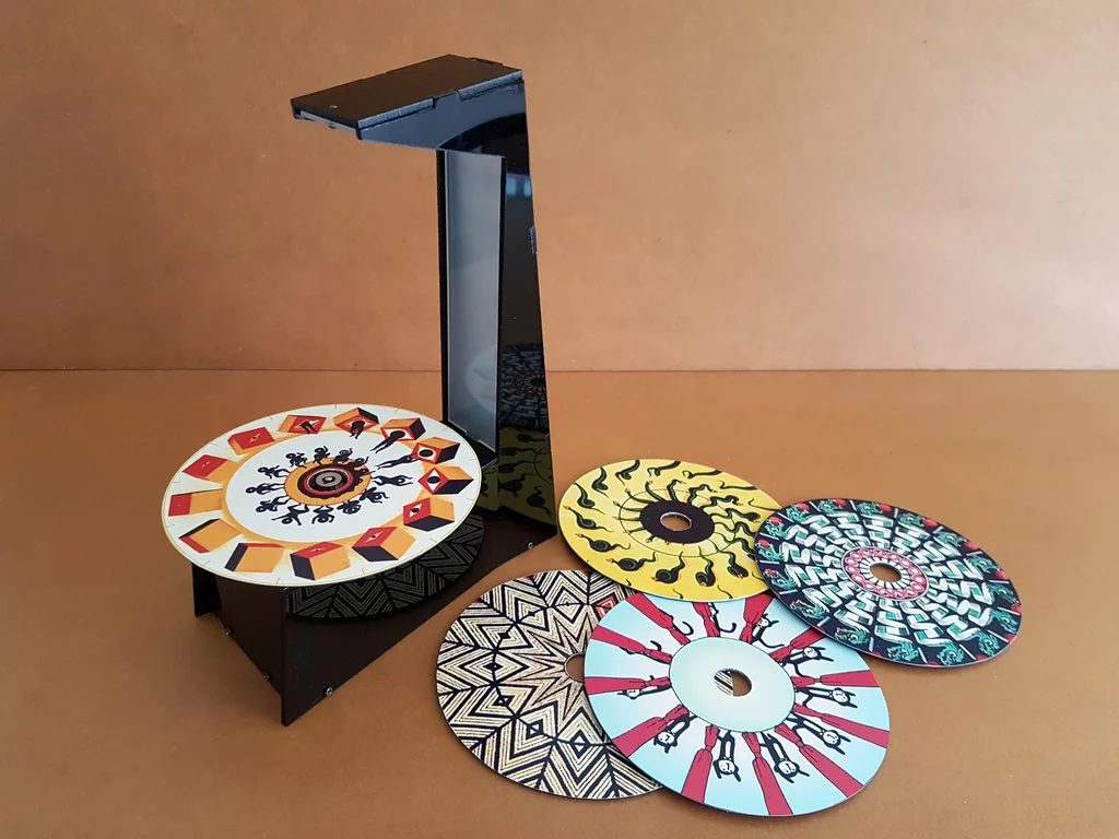
The phenakistoscope was invented in the 1800s as a way to view a series of moving pictures on a spinning disc. While the traditional implementation is ingenious in its own right, Nick Lim has created his own take on this venerable concept, using strobing light to break up frames instead of the slits-and-mirror arrangement of the original.
His system utilizes a repurposed CD-ROM BLDC motor to rotate the discs — which feature phenakistoscope patterns that were printed out and pasted on top — and an overhead array of strobing LEDs to make the images come to life.
An Arduino Nano controls the device, regulating motor speed and direction via a pair of L293D ICs, along with strobing frequency using a MOSFET. The result is a looping mini-video player that, unlike its inspiration, allows a few people to observe the animations at the same time!
Arduino MKR IoT Carrier: Control what you want, how you want to!
Arduino Team — February 24th, 2021
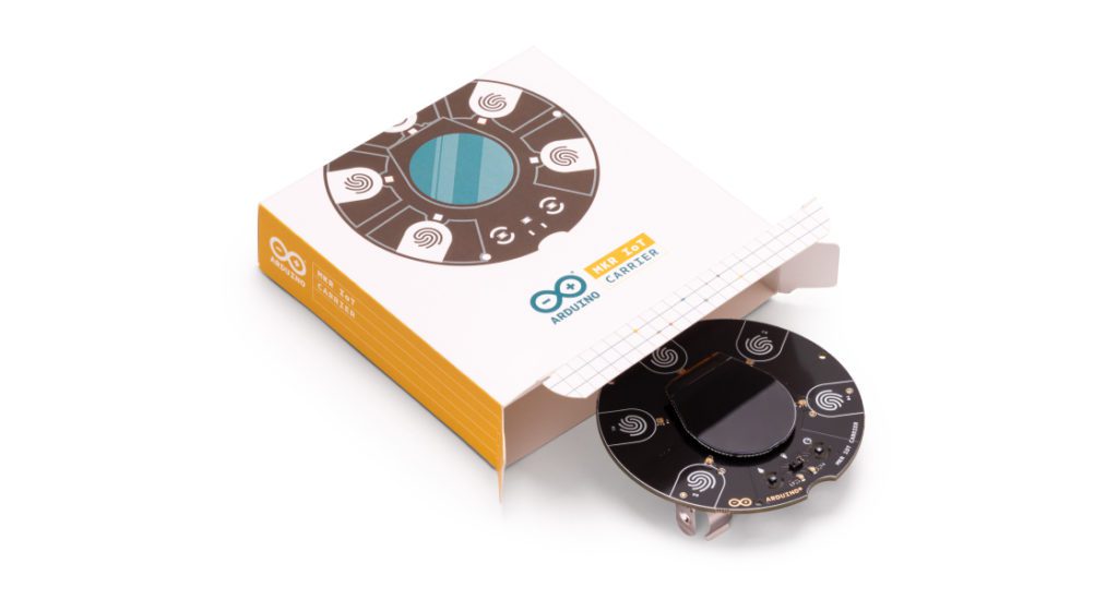
By popular demand, we are pleased to announce that it’s now possible to buy the Arduino MKR IoT Carrier. Originally forming a key part of the Arduino Oplá IoT Kit, we’ve responded to our community to make the carrier available on its own, thus enabling you to benefit from having a bunch of sensors, actuators, and a display all featured on the one board — making it quicker and easier to take your IoT projects to the next level.
Featuring a large set of built-in sensors and actuators as well as a useful color display, the carrier lets you focus on prototyping your IoT ideas right away by saving on the hassle of wiring and soldering these components.
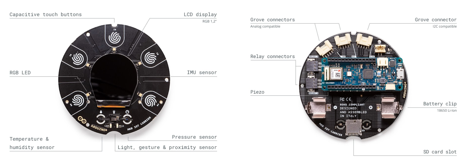
The carrier can become a WiFi, LoRa, NB-IoT or GSM-compatible device by seamlessly connecting to any MKR family board. Building a user interface for these boards is easy with the embedded color OLED screen, five capacitive touch buttons, and the five RGB LEDs. The integrated sensors (temperature, humidity, pressure, RGBC light, gesture and proximity) allow you to map the environment around the carrier, and should you need to capture any other data there are over 100 additional Grove sensors that can easily be connected directly to the carrier.
Here’s are quick demo of the carrier’s capabilities! (Special shout out to Mirko Pacioni and Fill Connesso for creating this demo.)
Capture and store all the data locally on an SD card, or connect your MKR family board to the IoT Cloud for real-time data captured, storage, and visualization.
The MKR IoT Carrier features:
Round OLED display
Five RGB LEDs
Five capacitive touch buttons
On-board sensors (temperature, humidity, pressure, RGBC light, gesture and proximity)
Buzzer
IMU (Three-axis accelerometer sensor and three-axis gyroscope sensor)
Two 24V relays
MicroSD card holder (SD card not included)
Plug-and-play Grove connectors for external sensors — two analog and one digital (I2C)
18650 Li-ion rechargeable battery holder (battery not included)
The MKR IoT Carrier is now available to purchase from the Arduino online store for €48 / $57.60 — find infinite possibilities for all your IoT projects
Interested in learning how to build IoT projects, then we have the perfect choice of kits for you, both featuring the MKR IoT Carrier. The Arduino Explore IoT Kit is the ideal kit to learn about the Internet of Things and what you can do with it, while the Arduino Oplá IoT Kit is great for experiencing the benefits of IoT at home or in the office with eight out-of-the-box IoT projects controlled on the Arduino IoT Cloud.
Bikelangelo is a water-dispensing graffiti bicycle trailer
Arduino Team — February 22nd, 2021
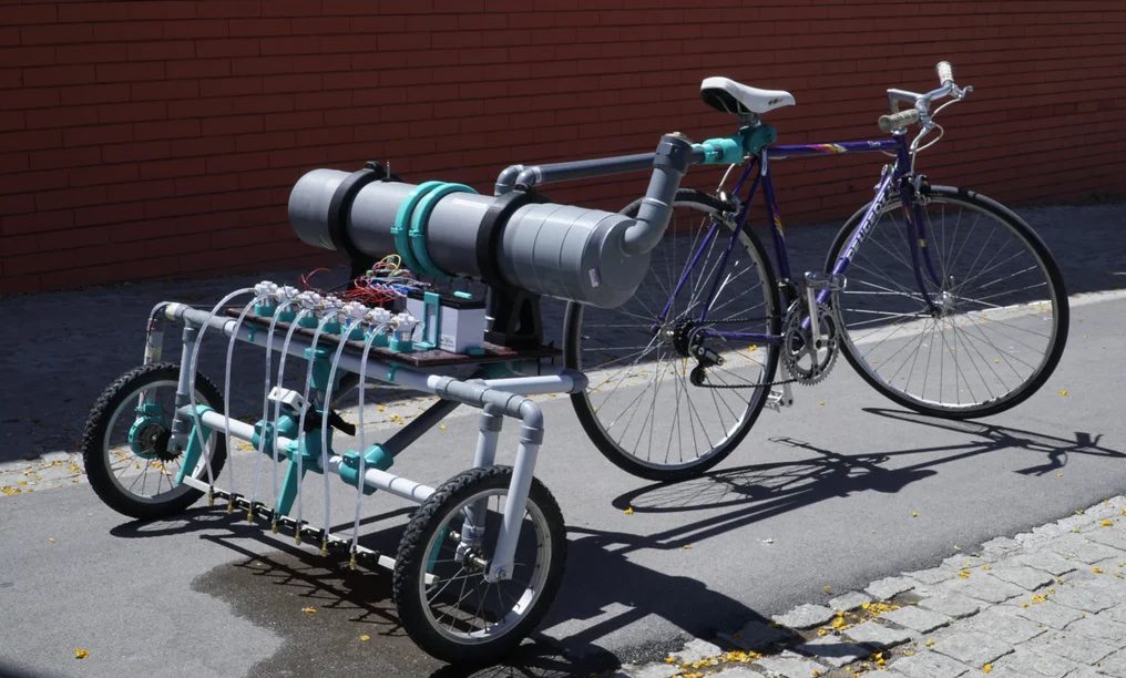
Inspired by persistence of vision (POV) projects, Sagarrabanana built a system that incrementally dispenses water as pixels on a flat surface, creating ephemeral dot matrix messages/images. This so-called “Bikelangelo” device is towed by a bicycle for ultra-mobile marking, and uses a pressurized tank for fluid storage.
As he pedals, a series of seven valve open and close under Arduino Nano control. A Hall-effect sensor allows it to dispense accurately based on the bike’s speed, and a Bluetooth phone connection via an HC-05 module is implemented for text input on the go.
You can see Bikelangelo in action in the quick clip below, and more information about the project – including two longer videos in Spanish – is available in Sagarrabanana’s write-up.
This robotic cue can turn anyone into a pool shark
Arduino Team — February 22nd, 2021
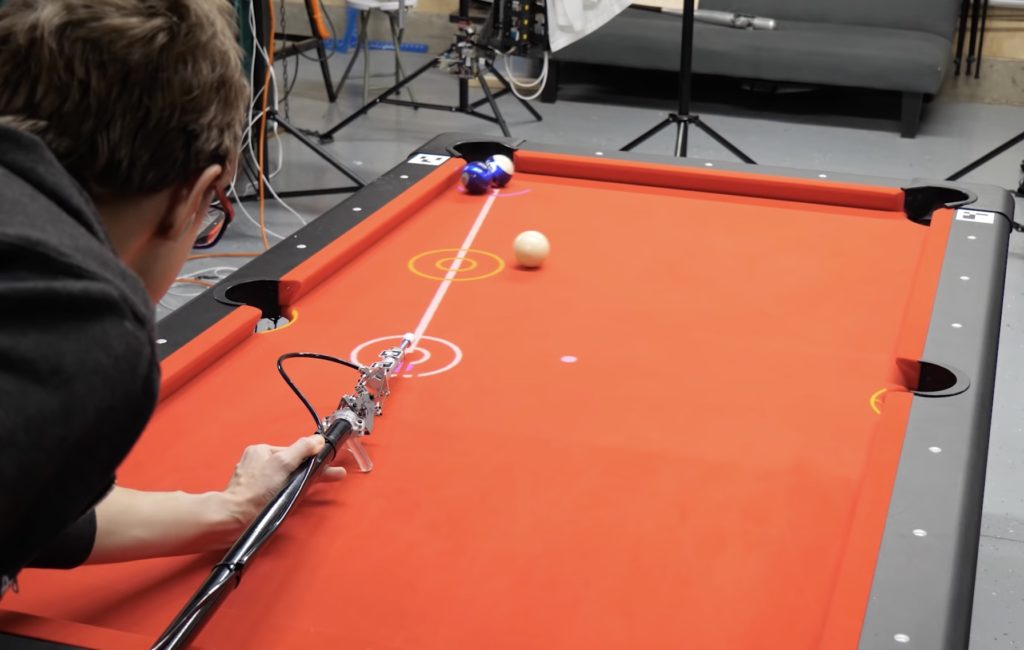
If you want to get better at billiards, the conventional wisdom is to practice. However, if you’re YouTuber Shane Wighton, you build a robotic cue to play the game for you.
His device looks like a cross between a pool stick, a sci-fi robot, and a heavily-modified weed wacker. Instead of precisely manipulating the cue, you just put it roughly in place, hit the trigger, and let it sink the shot.
The setup employs a servo/linkage-controlled platform for precise aiming, and a pneumatic actuator that pushes the tip into the selected ball when ready. An Arduino board is implemented to fire the actuator via a solenoid valve, and it can increase or decrease pressure with two other valves based on gauge input. Computer vision is used to sense ball and cue position, and the system even projects alignment guides and predicted trajectories on the table itself.
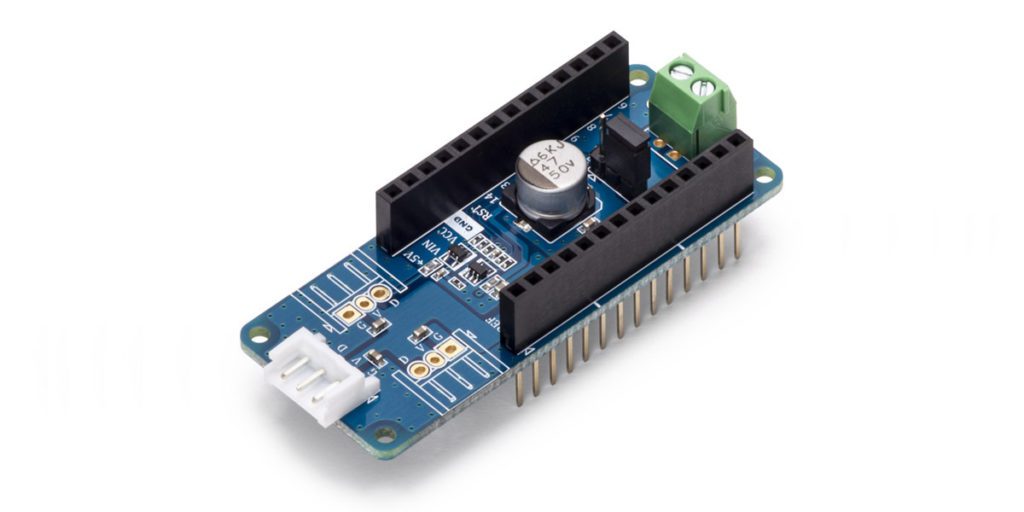
As part of the “Works with Arduino™” program, the DYNAMIXEL SHIELD expands the capabilities of the MKR family, opening up the opportunity to drive the DYNAMIXEL smart servos and create stunning robotics projects.
The “Works with Arduino” program ensures both the compatibility and quality of the shield within the Arduino ecosystem. Thus, the shield is fully supported by a set of high-quality libraries that are available in the Arduino IDE.
Combine the ROBOTIS DYNAMIXEL SHIELD with Arduino MKR boards to:
Control up to 253 servos connected in a daisy chain
Get real-time feedback like position, velocity, voltage, current, temperature, moving status, and additional items
Fine-tune motion characteristics
Expand existing systems, and/or swap units for similar or upgraded models
The ROBOTIS DYNAMIXEL SHIELD for the Arduino MKR series is available for pre-order on the Arduino online store.
This bin will sort your trash and recyclables automatically
Arduino Team — February 18th, 2021
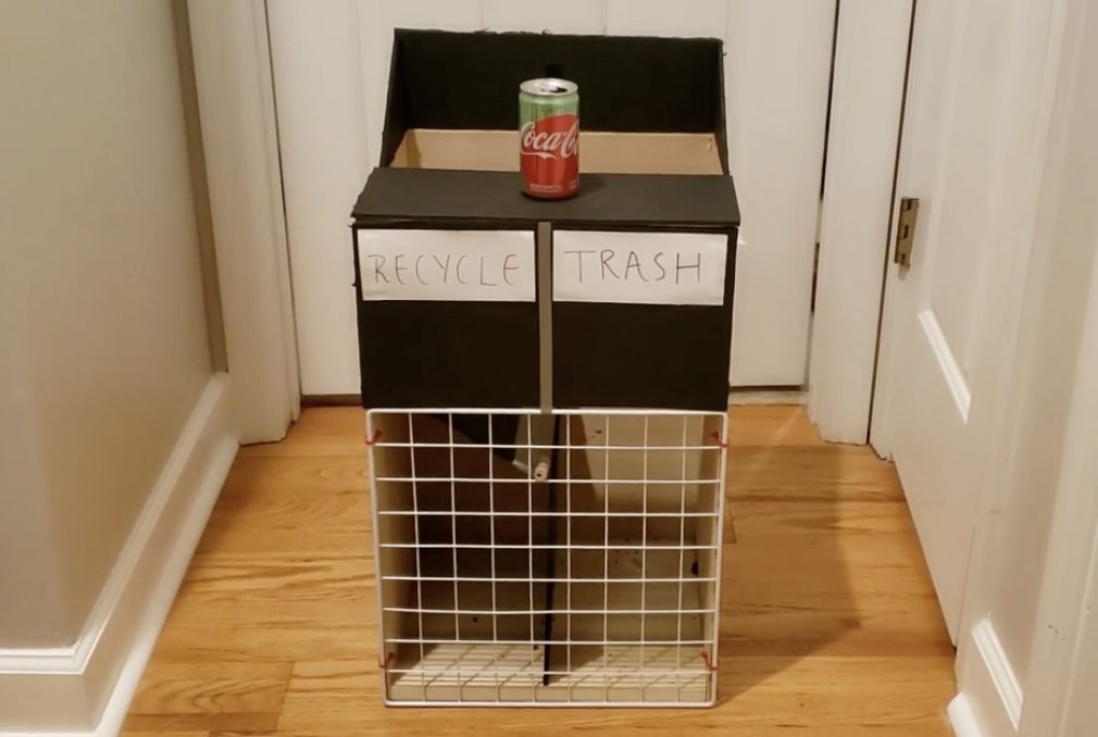
Often you might see a recycling bin next to a trash can, and notice that someone else has thrown their waste into the wrong container. To help with this conundrum, the team of Shalin Jain, Viraj Singh, Edward Chen, and Joshua Kim created a double-sided container that sorts things automatically.
Their device, dubbed “Splash,” takes a webcam image of the item presented to it, analyzes this with a Python script and the Azure Custom Vision API, and reports back to an Arduino Uno controller with its findings. Depending on the results, the Arduino then uses a driver board and motor to properly position a flap, directing refuse into in the correct bin.
This program can tell if you paid attention to text
Arduino Team — February 18th, 2021
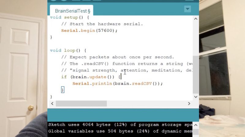
When you read a book, or… other website, you may find your mind wandering from time to time. This isn’t always a big deal, but if you want to ensure that you’re getting every last bit of information on a page, YouTuber “I made this” may have the perfect solution.
His “program that could tell if you are paying attention” employs eye tracking to see where on the page you’re looking, and correlates this with input from a brainwave sensor. Conveniently, the particular unit used here (salvaged from a NeuroSky toy) outputs an attention value from 0-100. An Arduino board reads the EEG directly and passes data along to the computer, which then highlights text green for “paid attention,” and red for “not paying attention.”
This article was written by Valentina Chinnici, Arduino Education Product Manager.
The last year has clearly been challenging for educators around the world due to the pandemic. Yet despite these difficult times, educators and students haven’t stopped getting hands-on and experimenting with STEM.
But how is it possible to create a systematic environment for student ideas through scientific observation when the science lab is no longer accessible?
It’s down to creativity and innovation, which haven’t been put on hold even during a pandemic. Teachers have had to adapt quickly to this fast-changing environment, and technologies like Arduino have supported this adaptation, providing educators with flexible tools to keep experimenting from home.
Arduino is committed to making STEM accessible for all students, with free tools and resources like the Arduino Science Journal app to collect data, leveraging either your mobile device or external sensors connected to Arduino, or a portable science lab for your remote needs (now on sale).
Teachers can also take advantage of different boards to experiment with science, which is what UK-based physics teacher, Alan Bates, did. Bates created an experiment to demonstrate the phenomenon known as the conservation of momentum, published in the February edition of The Physics Teacher.
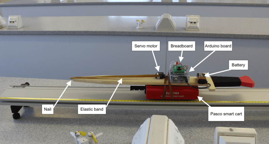
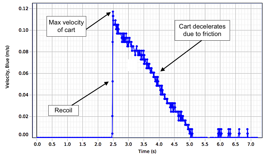
Bates combined an Arduino Uno Rev3 and a PASCO Smart Cart to create a movable rubber band launcher to investigate the conservation of momentum, and the energy transferred by the system as the potential energy of the rubber band is released. The Arduino board was used instead to activate the motion releasing the rubber band, and consequently, the cart.
The launcher was made with a wooden stick, a nail, and the rubber band, placed on a low-friction track, and mounted on top of a PASCO smart cart base. Masses are added to the cart every three measurements of recoil velocity.
Thanks to this scientific investigation, Bates was able to demonstrate and verify that, “elastic potential energy is not only transferred into kinetic energy, but also into other types of energy that include thermal and sound energy.”
For more information on the findings and analysis of the Conservation of Momentum with Dual Technologies, get your copy of the February edition of The Physics Teacher.
Play Simon and the piano on this glowing geodesic dome
Arduino Team — February 18th, 2021
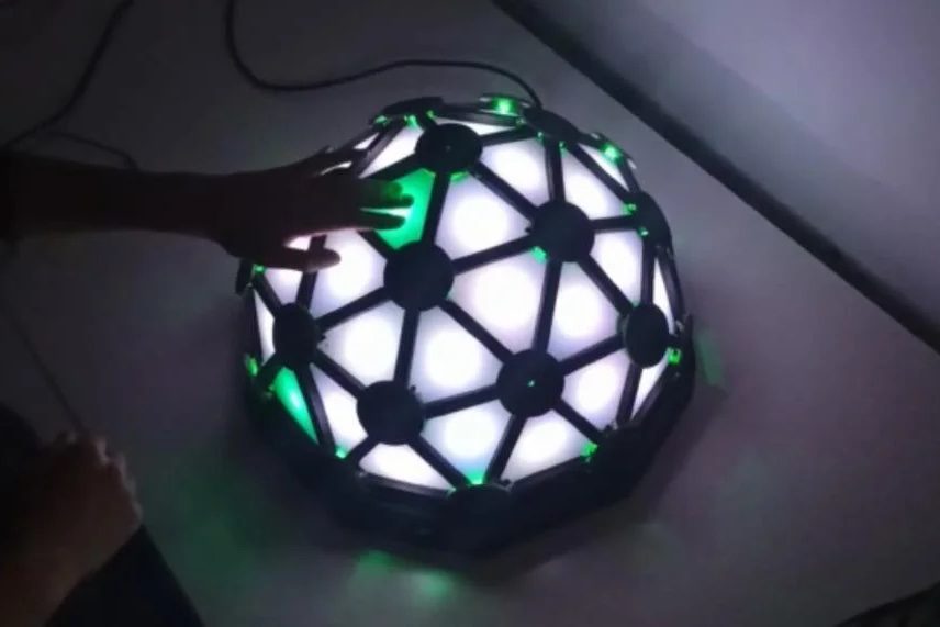
Geodesic domes, approximately spherical structures made from an arrangement of triangular faces, are fascinating in and of themselves. Add light and sound, as was done here by students at the University of Málaga in Spain, and you have something truly magical.
Their device is a derivation Jon Bumstead’s larger dome project, shrinking his 120-triangle design down to a more manageable 40. The frame was constructed out of wood and 3D-printed PLA, with triangle measurements calculated using this Desert Domes tool.
An Arduino Uno controls the system’s programmable LED and sound output, while IR sensors with 74LS151 multiplexers allow for interaction. The dome features several modes, which include creating colorful patterns at the touch of each triangle, producing music, and even playing the classic game of Simon. You can see it in action below!
Say hi to HuggieBot 2.0, a robot that knows when to hug and when to let go
Arduino Team — February 16th, 2021
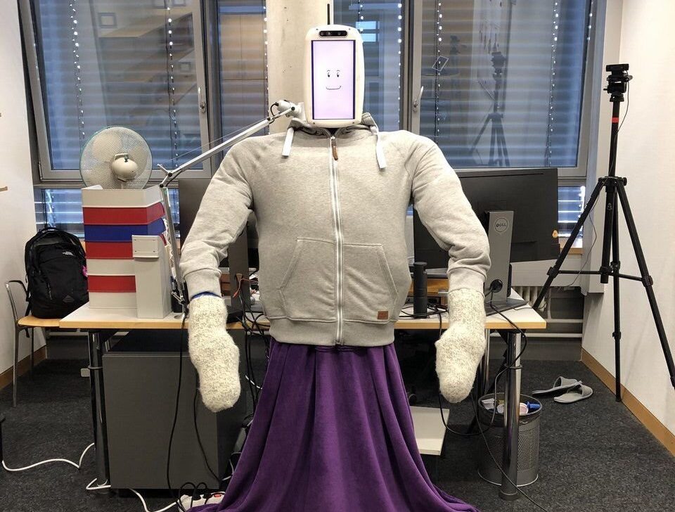
Do you need a hug? Are friends and family not around? As seen here, researchers from the Max Planck Institute for Intelligent Systems (MPI-IS) and ETH Zürich may have just the solution in the form of HuggieBot 2.0.
Based on a previous robot created by one of the paper’s co-authors Alexis E. Block, HuggieBot 2.0 uses computer vision to detect when a participant is approaching for an embrace, and wraps its 6-DOF JACO arms around them when in position.
An LCD screen allows HuggieBot to output facial expressions, which along with overall robot functions, are controlled by an onboard computer. To determine when to end the hug, it employs an inflatable “HuggieChest” microphone and pressure sensor setup, read with the help of an Arduino Uno. When a person releases the hug, the robot can do the same, averting any robo-human awkwardness.
This article was written by Silvano Cerza from the Arduino Tooling Team.
Big news from the Arduino Tooling team: The new Arduino CLI version 0.16.0 has been released!
You can now use arduino-cli core list –all to return all installed and installable platforms, including those installed manually in the Sketchbook hardware folder.
We also have a breaking change to mention:
7e1ff323 [breaking] Fix export binaries binding not working in gRPC interface (#1171)
It’s in the CLI gRPC interface, so command line users should not be affected! You will find all the details in our handy upgrading guide.
Arduino Day, which will be held on March 27th this year, is the celebration of the Arduino community and the achievements of its members. The last several years have seen more than 3,000 community initiatives, organized from project exhibitions to talks and workshops, spanning across hundreds of countries worldwide.
In a year of social distancing, we realized (even more) the magnitude of the Arduino open-source community. Connecting us all, our community has broken down the barriers of physical distances and self-isolation. While the pandemic has made us feel further apart, Arduino has brought us a bit closer.
For this reason, Arduino Day 2021 will be titled ‘Undistancing: Open Makes Us Close’ — a phrase that embodies the power of the open source community to shorten any physical distance through new opportunities to collaborate, innovate, and get (virtually) closer.
UNDISTANCING conveys the disruptive power of Arduino users to unite in a time when it’s needed more than ever.
OPEN MAKES US CLOSE represents the ability of our community to transform a burden into a chance to connect, collaborate, and create as one. It’s a call to shorten as many distances as possible and to explore new ideas and technologies, together.
Arduino Day is open to anyone, either as a local organizer or participant. If you want to organize a festivity of your own, please fill out this online form and submit your proposal by March 14th.
Over the next few weeks, make sure to visit the Arduino Day website to learn more or locate an event in your area. Moreover, don’t forget to spread the word on social media using the hashtag #ArduinoD21!
We love our community and their safety is our priority. For this reason, we invite the organizers of local Arduino Day events to celebrate online. For all events, we recommend following the “Key planning recommendations for Mass Gatherings in the context of the current COVID-19 outbreak” released by the World Health Organization, and check the information released by your government in order to enjoy Arduino Day safely!
Science and technology empower people to change the world. At Arduino, we work every day to make them simple and accessible to anyone regardless of gender, ethnicity, age, background, nationality, and sexuality. Unfortunately, not all contributions are given the same visibility, that’s why we are celebrating the International Day of Women and Girls in Science by highlighting six scientists who were not honored enough for their achievements. Giving these women the visibility they deserve, we hope to inspire our community to innovate in a more inclusive way and to create a better future together.
Lise Meitner (1878 – 1968)
Born in Austria, Lise Meitner made an extraordinary contribution to nuclear physics and oversaw his explosive potential. After the Ph.D. in Physics, she moved to Berlin and started working with chemist Otto Hahn. When Nazis annexed Austria, Meitner, who was Jewish, had to move to Stockholm. She kept working with Otto Hahn and contributed to the theory of nuclear fission. Hahn won the 1944 Nobel Prize, but could not credit Meitner for her contribution.
Alice Ball (1892 – 1916)
American born pharmaceutical chemist Alice Ball developed at age 23 a technique to make the oil injectable and absorbable by the body. Her method — credited only after her death as ‘’Ball method’’ — represented the most effective treatment for leprosy during the early 20th century. Tragically, Ball died of an illness before she could publish her results, and another chemist later published without giving Ball credit.
Chien-Shiung Wu (1912 – 1997)
Chinese-American physicist Chien-Shiung Wu is best known for conducting the “Wu Experiment”, which disproved a hypothetical physical law called the conservation of parity. Her experiment paved the way for several studies that led her colleagues Tsung-Dao Lee and Chen Ning Yang to win the 1957 Nobel Prize in Physics.
Rosalind Franklin (1920 – 1958)
When Rosalind Franklin took in 1952 the photo 51 in her lab — the first picture of DNA — she had no idea that she would become the center of a scientific controversy. The British chemist and accomplished X-ray crystallographer’s image was shared with James Watson and Francis Crick, who were working on identifying the structure of DNA. Franklin’s picture was key to deduce that DNA took the form of a double helix. However, in their paper about the discovery, they only mentioned Franklin in a footnote.
Katherine Johnson (1918 – 2020 )
With her calculations of orbital mechanics, mathematician Katherine Johnson played a critical role in the success of the first NASA crewed spaceflights. Trained as a human-computer, Johnson mastered complex manual calculations, mastering trajectories, launch windows and emergency return paths for spaceflights. Until 1958, Johnson and her African-American colleagues were required to work and eat in offices separate from those of their white peers. In 2019, Johnson was awarded the Congressional Gold Medal.
Jocelyn Bell Burnell (1943)
Irish Professor Dame Jocelyn Bell Burnell is credited with one of the most important discoveries of the last century: the radio pulsars. Pulsars are the by-products of supernova explosions; thanks to them, scientists can measure cosmic distances, study extreme states of matter and search for planets beyond Earth’s solar system. Pulsar’s discovery was recognized by the award of the 1974 Nobel Prize in Physics; however, she was not one of the recipients of the prize.
In this deep dive article, performance optimization specialist Larry Bank (a.k.a The Performance Whisperer) takes a look at the work he did for the Arduino team on the latest version of the Arduino_OV767x library.
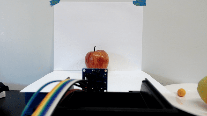
Arduino recently announced an update to the Arduino_OV767x camera library that makes it possible to run machine vision using TensorFlow Lite Micro on your Arduino Nano 33 BLE board.
If you just want to try this and run machine learning on Arduino, you can skip to the project tutorial.
The rest of this article is going to look at some of the lower level optimization work that made this all possible. There are higher performance industrial-targeted options like the Arduino Portenta available for machine vision, but the Arduino Nano 33 BLE has sufficient performance with TensorFlow Lite Micro support ready in the Arduino IDE. Combined with an OV767x module makes a low-cost machine vision solution for lower frame-rate applications like the person detection example in TensorFlow Lite Micro.
Need for speed
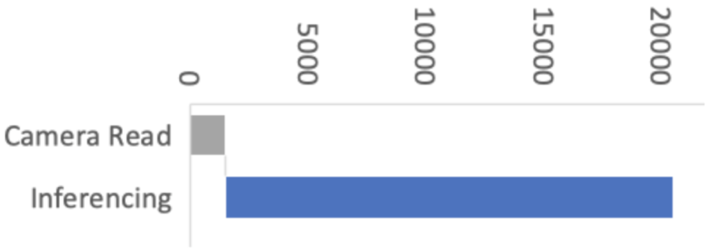
Recent optimizations done by Google and Arm to the CMSIS-NN library also improved the TensorFlow Lite Micro inference speed by over 16x, and as a consequence bringing down inference time from 19 seconds to just 1.2 seconds on the Arduino Nano 33 BLE boards. By selecting the person_detection example in the Arduino_TensorFlowLite library, you are automatically including CMSIS-NN underneath and benefitting from these optimizations. The only difference you should see is that it runs a lot faster!
The CMSIS-NN library provides optimized neural network kernel implementations for all Arm’s Cortex-M processors, ranging from Cortex-M0 to Cortex-M55. The library utilizes the processor’s capabilities, such as DSP and M-Profile Vector (MVE) extensions, to enable the best possible performance.
The Arduino Nano 33 BLE board is powered by Arm Cortex-M4, which supports DSP extensions. That will enable the optimized kernels to perform multiple operations in one cycle using SIMD (Single Instruction Multiple Data) instructions. Another optimization technique used by the CMSIS-NN library is loop unrolling. These techniques combined will give us the following example where the SIMD instruction, SMLAD (Signed Multiply with Addition), is used together with loop unrolling to perform a matrix multiplication y=a*b, where
a=[1,2]
and
b=[3,5 4,6]
a, b are 8-bit values and y is a 32-bit value. With regular C, the code would look something like this:
However, using loop unrolling and SIMD instructions, the loop will end up looking like this:
a_operand = a[0] | a[1] << 16 // put a[0], a[1] into one variable
  for(i=0; i<2; ++i)
    b_operand = b[0][i] | b[1][i] << 16 // vice versa for b
    y[i] = __SMLAD(a_operand, b_operand, y[i])
This code will save cycles due to
fewer for-loop checks
__SMLAD performs two multiply and accumulate in one cycle
This is a simplified example of how two of the CMSIS-NN optimization techniques are used.
Figure 1: Performance with initial versions of libraries
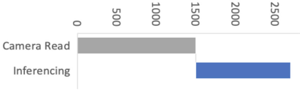
Figure 2: Performance with CMSIS-NN optimizations
This improvement means the image acquisition and preprocessing stages now have a proportionally bigger impact on machine vision performance. So in Arduino our objective was to improve the overall performance of machine vision inferencing on Arduino Nano BLE sense by optimizing the Arduino_OV767X library while maintaining the same library API, usability and stability.
Figure 3: Performance with CMSIS-NN and camera library optimizations
For this, we enlisted the help of Larry Bank who specializes in embedded software optimization. Larry’s work got the camera image read down from 1500ms to just 393ms for a QCIF (176×144 pixel) image. This was a great improvement!
Let’s have a look at how Larry approached the camera library optimization and how some of these techniques can apply to your Arduino code in general.
Performance optimizing Arduino code
It’s rarely practical or necessary to optimize every line of code you write. In fact there are very good reasons to prioritize readable, maintainable code. Being readable and optimized don’t necessarily have to be mutually exclusive. However, embedded systems have constrained resources, and when applications demand more performance, some trade-offs might have to be made. Sometimes it is necessary to restructure algorithms, pay attention to compiler behavior, or even analyze timing of machine code instructions in order to squeeze the most out of a microcontroller. In some cases this can make the code less readable — but the beauty of an Arduino library is that this can be abstracted (hidden) from user sketch code beneath the cleaner library function APIs.
What does “Camera.readFrame” do?
We’ve connected a camera to the Arduino. The Arduino_OV767X library sets up the camera and lets us transfer the raw image data from the camera into the Arduino Nano BLE memory. The smallest resolution setting, QCIF, is 176 x 144 pixels. Each pixel is encoded in 2 bytes. We therefore need to transfer at least 50688 bytes (176 x 144 x 2 ) every time we capture an image with Camera.readFrame. Because the function is performing a byte read operation over 50 thousand times per frame, the way it’s implemented has a big impact on performance. So let’s have a look at how we can most efficiently connect the camera to the Arduino and read a byte of data from it.
Philosophy
I tend to see the world of code through the “lens” of optimization. I’m not advocating for everyone to share my obsession with optimization. However, when it does become necessary, it’s helpful to understand details of the target hardware and CPU. What I often encounter with my clients is that their code implements their algorithm neatly and is very readable, but it’s not necessarily ‘performance friendly’ to the target machine. I assume this is because most people see code from a top-down approach: they think in terms of the abstract math and how to process the data. My history in working with very humble machines and later turning that into a career has flipped that narrative on its head. I see software from the bottom up: I think about how the memory, I/O and CPU registers interact to move and process the data used by the algorithm. It’s often possible to make dramatic improvements to the code execution speed without losing any of its readability. When your readable/maintainable solution still isn’t fast enough, the next phase is what I call ‘uglification.’ This involves writing code that takes advantage of specific features of the CPU and is nearly always more difficult to follow (at least at first glance!).
Optimization methodology
Optimization is an iterative process. I usually work in this order:
Test assumptions in the algorithm (sometimes requires tracing the data)
Make innocuous changes in the logic to better suit the CPU (e.g. change modulus to logical AND)
Flatten the hierarchy or simplify overly nested classes/structures
Test any slow/fast paths (aka statistics of the data — e.g. is 99% of the incoming data 0?)
Go back to the author(s) and challenge their decisions on data precision / storage
Make the code more suitable for the target architecture (e.g. 32 vs 64-bit CPU registers)
If necessary (and permitted by the client) use intrinsics or other CPU-specific features
Go back and test every assumption again
If you would like to investigate this topic further, I’ve written a more detailed presentation on Writing Performant C++ code.
Depending on the size of the project, sometimes it’s hard to know where to start if there are too many moving parts. If a profiler is available, it can help narrow the search for the “hot spots” or functions which are taking the majority of the time to do their work. If no profiler is available, then I’ll usually use a time function like micros() to read the current tick counter to measure execution speed in different parts of the code. Here is an example of measuring absolute execution time on Arduino:
long lTime;
  lTime = micros();
  <do the work>
  iTime = micros() - lTime;
  Serial.printf(“Time to execute xxx = %d microseconds\n”, (int)lTime);
I’ve also used a profiler for my optimization work with OpenMV. I modified the embedded C code to run as a MacOS command line app to make use of the excellent XCode Instruments profiler. When doing that, it’s important to understand how differently code executes on a PC versus embedded — this is mostly due to the speed of the CPU compared to the speed of memory.
Pins, GPIO and PORTs
One of the most powerful features of the Arduino platform is that it presents a consistent API to the programmer for accessing hardware and software features that, in reality, can vary greatly across different target architectures. For example, the features found in common on most embedded devices like GPIO pins, I2C, SPI, FLASH, EEPROM, RAM, etc. have many diverse implementations and require very different code to initialize and access them.
Let’s look at the first in our list, GPIO (General Purpose Input/Output pins). On the original Arduino Uno (AVR MCU), the GPIO lines are arranged in groups of 8 bits per “PORT” (it’s an 8-bit CPU after all) and each port has a data direction register (determines if it’s configured for input or output), a read register and a write register. The newer Arduino boards are all built around various Arm Cortex-M microcontrollers. These MCUs have GPIO pins arranged into groups of 32-bits per “PORT” (hmm – it’s a 32-bit CPU, I wonder if that’s the reason). They have a similar set of control mechanisms, but add a twist — they include registers to SET or CLR specific bits without disturbing the other bits of the port (e.g. port->CLR = 1; will clear GPIO bit 0 of that port). From the programmer’s view, Arduino presents a consistent set of functions to access these pins on these diverse platforms (clickable links below to the function definitions on Arduino.cc):
For me, this is the most powerful idea of Arduino. I can build and deploy my code to an AVR, a Cortex-M, ESP8266 or an ESP32 and not have to change a single line of code nor maintain multiple build scripts. In fact, in my daily work (both hobby and professional), I’m constantly testing my code on those 4 platforms. For example, my LCD/OLED display library (OneBitDisplay) can control various monochrome LCD and OLED displays and the same code runs on all Arduino boards and can even be built on Linux.
One downside to having these ‘wrapper’ functions hide the details of the underlying implementation is that performance can suffer. For most projects it’s not an issue, but when you need to get every ounce of speed out of your code, it can make a huge difference.
Camera data capture
One of the biggest challenges of this project was that the original OV7670 library was only able to run at less than 1 frame per second (FPS) when talking to the Nano 33. The reason for the low data rate is that the Nano 33 doesn’t expose any hardware which can directly capture the parallel image data, so it must be done ‘manually’ by testing the sync signals and reading the data bits through GPIO pins (e.g. digitalRead) using software loops. The Arduino pin functions (digitalRead, digitalWrite) actually contain a lot of code which checks that the pin number is valid, uses a lookup table to convert the pin number to the I/O port address and bit value and may even disable interrupts before reading or changing the pin state. If we were to use the digitalRead function for an application like this, it would limit the data capture rate to be too slow to operate the camera. You’ll see this further down when we examine the actual code used to capture the data.
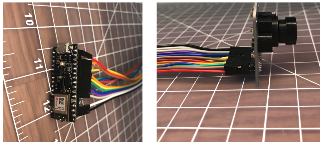
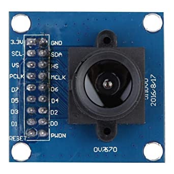
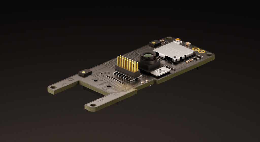
First, a quick review of the OV7670 camera module: According to its datasheet, it’s capable of capturing a VGA (640×480) color image at up to 30 FPS. The kit used for this project has the camera mounted to a small PCB and presents an 8-bit parallel data bus and various sync signals.
It requires an external “master clock” (MCLK in the photo) to drive its internal state machine which is used to generate all of the other timing signals. The Nano 33 can provide this external clock source by using its I2S clock. The OV767X library sets this master clock to 16Mhz (the camera can handle up to 48Mhz) and then there is a set of configuration registers to divide this value to arrive at the desired frame rate. Only a few possible frame rates are available (1, 5, 10, 15, 20, and 30 FPS).
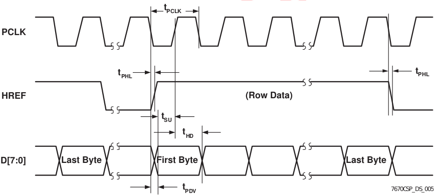
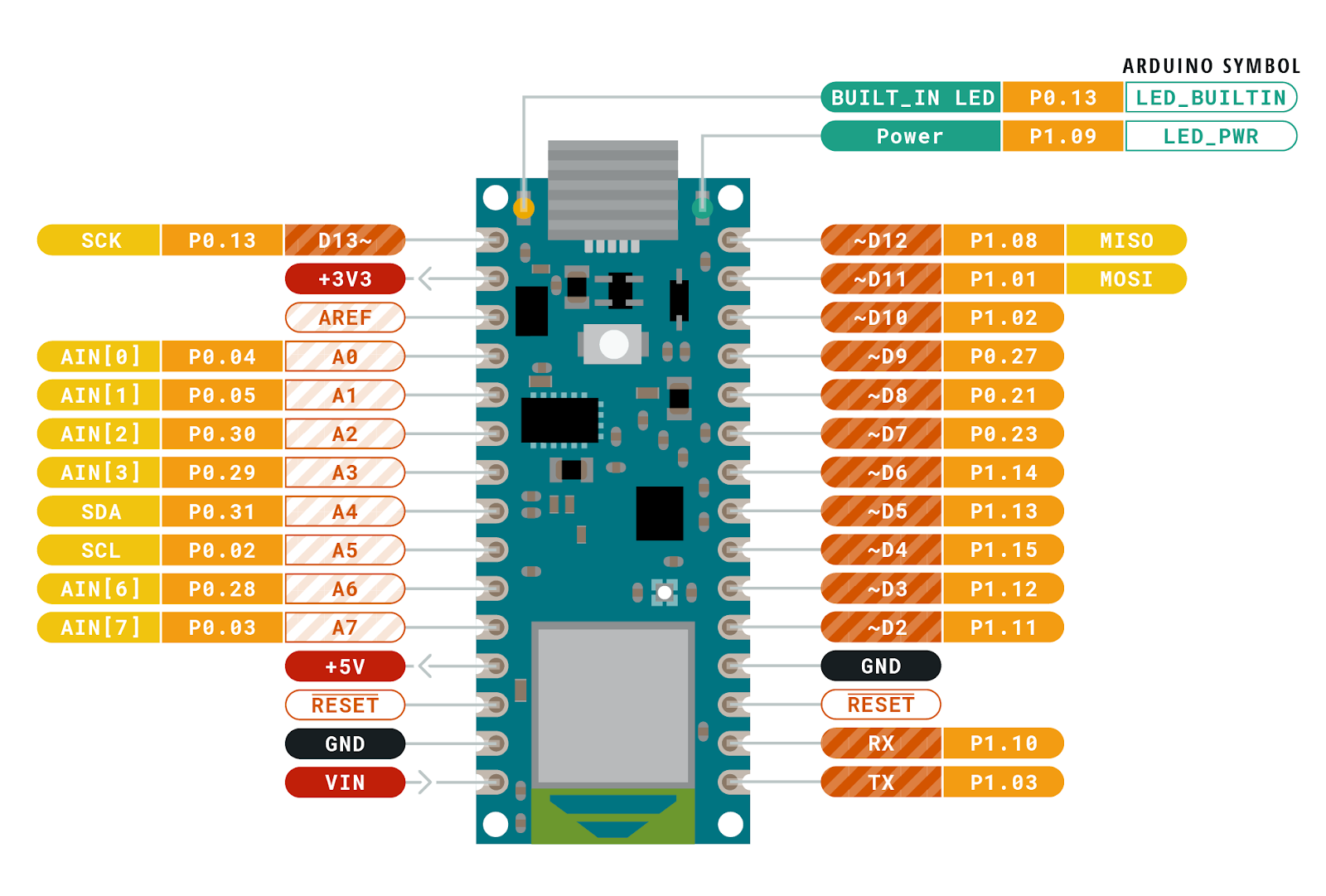
Above is one of the timing diagrams from the OV7670 datasheet. This particular drawing shows the timing of the data for each byte received along each image row. The HREF signal is used to signal the start and end of a row and then each byte is clocked in with the PCLK signal. The original library code read each bit (D0-D7) in a loop and combined them together to form each data byte. The image data comes quickly, so we have very little time to read each byte. Assembling them one bit at a time is not very efficient. You might be thinking that it’s not that hard of a problem to solve on the Nano 33. After all, it has 22 GPIO pins and the Cortex-M inside it has 32-bit wide GPIO ports, so just hook up the data bits sequentially and you’ll be able to read the 8 data bits in one shot, then Mission Accomplished™. If only things were that easy. The Nano 33 does have plenty of GPIO pins, but there isn’t a continuous sequence of 8 bits available using any of the pins! I’m guessing that the original code did it one bit at a time because it didn’t look like there was a better alternative. In the pinout diagram below, please notice the P0.xx and P1.xx numbers. These are the Cortex-M GPIO port 0 and 1-bit numbers (other Cortex-M processors would label them PA and PB).
I wasn’t going to let this little bump in the road stop me from making use of bit parallelism. If you look carefully at the bit positions, the best continuous run we can get is 6 bits in a row with P1.10 through P1.15. It’s not possible to read the 8 data bits in one shot…or is it? If we connect D0/D1 of the camera to P1.02/P1.03 and D2-D7 to P1.10-P1.15, we can do a single 32-bit read from port P1 and get all 8 bits in one shot. The bits are in order, but will have a gap between D1 and D2 (P1.04 to P1.09). Luckily the Arm CPU has what’s called a barrel shifter. It also has a smart instruction set which allows data to be shifted ‘for free’ at the same time the instruction is doing something else. Let’s take a look at how and why I changed the code:
Original:
uint8_t in = 0;
  for (int k = 0; k < 8; k++) {
     bitWrite(in, k, (*_dataPorts[k] & _dataMasks[k]) != 0);
  }
Optimized:
  uint32_t in = port->IN; // read all bits in parallel
  in >>= 2; // place bits 0 and 1 at the "bottom" of the
register
  in &= 0x3f03; // isolate the 8 bits we care about
  in |= (in >> 6); // combine the upper 6 and lower 2 bits
Code analysis
If you’re not interested in the nitty gritty details of the code changes I made, you can skip this section and go right to the results below.First, let’s look at what the original code did. When I first looked at it, I didn’t recognize bitWrite; apparently it’s not a well known Arduino bit manipulation macro; it’s defined as:
This macro was written with the intention of being used on GPIO ports (the variable value) where the logical state of bitvalue would be turned into a single write of a 0 or 1 to the appropriate bit. It makes less sense to be used on a regular variable because it inserts a branch to switch between the two possible outcomes. For the task at hand, it’s not necessary to use bitClear() on the in variable since it’s already initialized to 0 before the start of each byte loop. A better choice would be:
if (*_dataPorts[k] & _dataMasks[k]) in |= (1 << k);
The arrays _dataPorts[] and _dataMasks[] contain the memory mapped GPIO port addresses and bit masks to directly access the GPIO pins (bypassing digitalRead). So here’s a play-by-play of what the original code was doing:
Set in to 0
Set k to 0
Read the address of the GPIO port from _dataPorts[] at index k
Read the bit mask of the GPIO port from _dataMasks[] at index k
Read 32-bit data from the GPIO port address
Logical AND the data with the mask
Shift 1 left by k bits to prepare for bitClear and bitSet
Compare the result of the AND to zero
Branch to bitSet() code if true or use bitClear() if false
bitClear or bitSet depending on the result
Increment loop variable k
Compare k to the constant value 8
Branch if less back to step 3
Repeat steps 3 through 13, 8 times
Store the byte in the data array (not shown above)
The new code does the following:
Read the 32-bit data from the GPIO port address
Shift it right by 2 bits
Logical AND (mask) the 8 bits we’re interested in
Shift and OR the results to form 8 continuous bits
Store the byte in the data array (not shown above)
Each of the steps listed above basically translates into a single Arm instruction. If we assume that each instruction takes roughly the same amount of time to execute (mostly true on Cortex-M), then old vs. new is 91 versus 5 instructions to capture each byte of camera data, an 18x improvement! If we’re capturing a QVGA frame (320x240x2 = 153600 bytes), that becomes manymillionsof extra instructions.
Results
The optimized byte capture code translates into 5 Arm instructions and allows the capture loop to now handle a setting of 5 FPS instead of 1 FPS. The FPS numbers don’t seem to be exact, but the original capture time (QVGA @ 1 FPS) was 1.5 seconds while the new capture time when set to 5 FPS is 0.393 seconds. I tested 10 FPS, but readFrame() doesn’t read the data correctly at that speed. I don’t have an oscilloscope handy to probe the signals to see why it’s failing. The code may be fast enough now (I think it is), but the sync signals may become too unstable at that speed. I’ll leave this as an exercise to the readers who have the equipment to see what happens to the signals at 10 FPS.
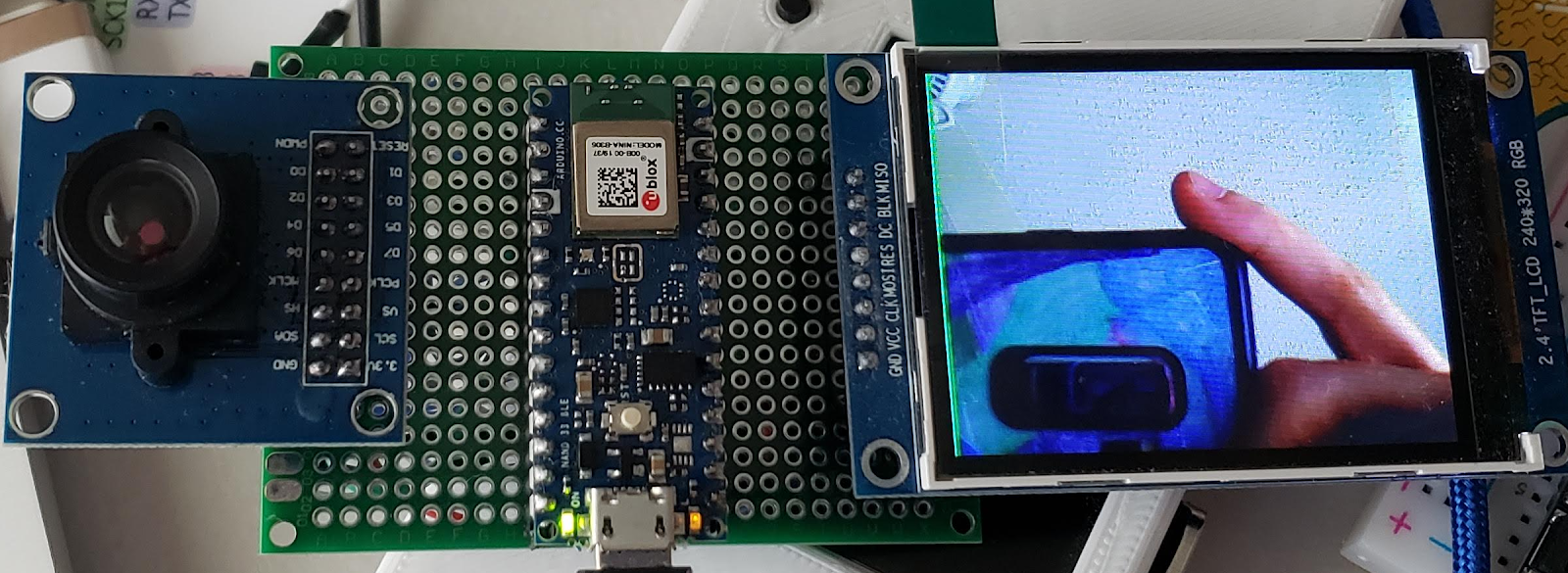
For the work I did on the OV767X library, I created a test fixture to make sure that the camera data was being received correctly. For ML/data processing applications, it’s not necessary to do this. The built-in camera test pattern can be used to confirm the integrity of the data by using a CRC32.
My tinned protoboard test fixture with 320×240 LCD
Note: The frames come one immediately after another. If you capture a frame and then do some processing and then try to capture another frame, you may hit the middle of the next frame when you call readFrame(). The code will then wait until the next VSync signal, so that frame’s capture time could be as much as 2x as long as a single frame time.
More tips
I enjoy testing the limits of embedded hardware, especially when it involves bits, bytes and pixels. I’ve written a few blog posts that explore the topics of speed and power usage if you’re interested in learning more about it.
Conclusion
The embedded microcontrollers available today are capable of handling jobs that were unimaginable just a few years ago.
Optimized ML solutions from Google and Edge Impulse are capable of running on low-cost, battery-powered boards (vision, vibration, audio, whatever sensor you want to monitor).
Python and Arduino programming environments can test your project idea with little effort.
Software can be written an infinite number of ways to accomplish the same task, but one constant remains: TANSTATFC (there ain’t no such thing as the fastest code).
Never assume the performance you’re seeing is what you’re stuck with. Think of existing libraries and generic APIs available through open source libraries and environments as a starting point.
Knowing a bit of info about the target platform can be helpful, but it’s not necessary to read the MCU datasheet. In the code above, the larger concept of Arm Cortex-M 32-bit GPIO ports was sufficient to accomplish the task without knowing the specifics of the nRF52’s I/O hardware.
Don’t be afraid to dig a little deeper and test every assumption.
If you encounter difficulties, the community is large and there are a ton of resources out there. Asking for help is a sign of strength, not weakness.
eMBee ONE turns an Arduino and an Altoids tin into an ’80s-style pocket computer
Arduino Team — February 9th, 2021
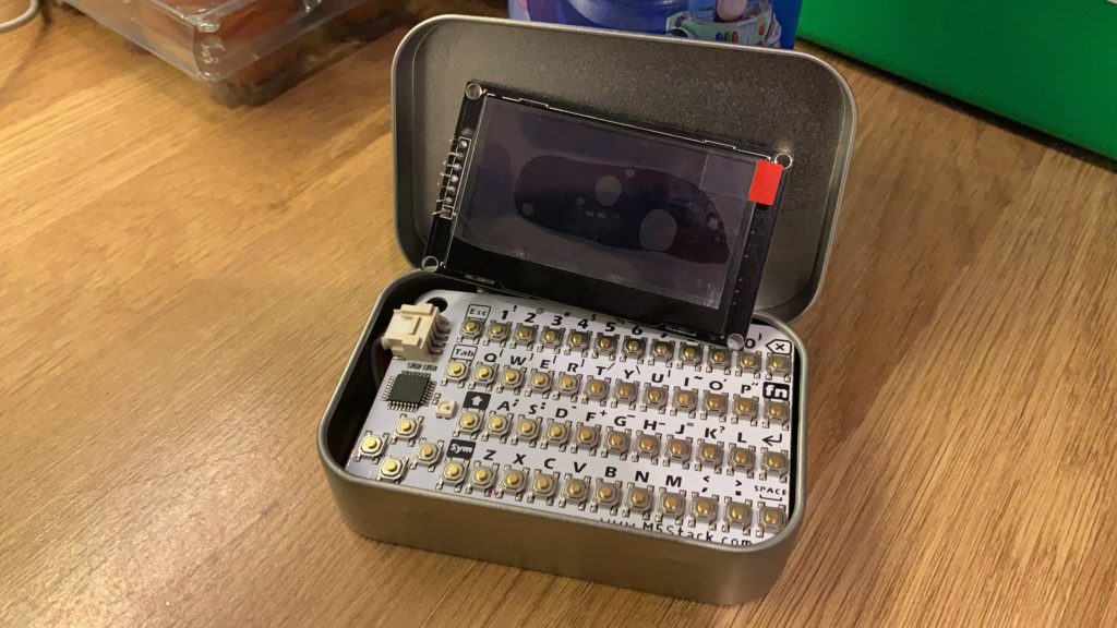
Matthew Begg wanted a pocket computer that had some of the charm of his 1980s vintage Casio FX-730P, so he decided to build his own.
His prototype device uses an Arduino Nano to boot into BASIC, and features a 1.54″ OLED display as well as a PCB-based QWERTY keyboard. Power is provided via a pair of AAA batteries, along with a boost converter. Most notably, however, the entire thing is meant to fit inside of an Altoids tin.
The unit, known as the “eMBee ONE,” can run an N-queen calculator benchmarking program in seven seconds – staggering compared to the FX-730’s time of seven minutes! An optional buzzer can be added to the device for sound output, and could perhaps be used to indicate when it’s done “thinking.”
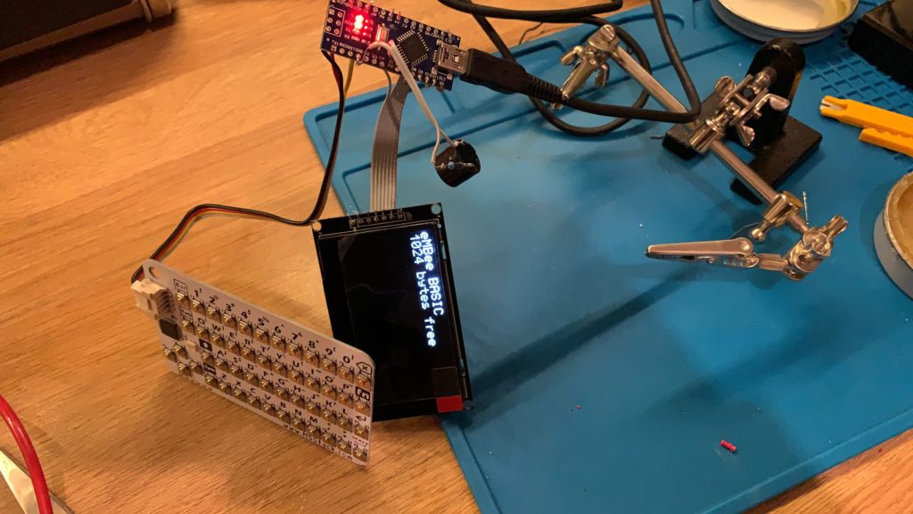
Based on Robin Edwards’ excellent Arduino BASIC, this is the software for a complete pocket computer, using an Arduino Nano, a CardKB I2C keyboard, and SPI OLED screen. The BASIC supports almost all the usual features, with float and string variables, multi-dimensional arrays, FOR-NEXT, GOSUB-RETURN, etc. Saving and loading from internal and external EEPROM is supported, as well as auto-running a program on power-up. You can also read and write from the analog and digital pins.
There’s about 1k of RAM available for your BASIC programs and variables, so its roughly equivalent to a Sinclair ZX81. The other 1k of RAM (on a Nano) is used for the keyboard and screen buffers, with a small bit of room left for the CPU stack. That works out quite well, since there’s a 1k EEPROM on the Nano so if your program fits in the basic environment, it will fit when saved to EEPROM!
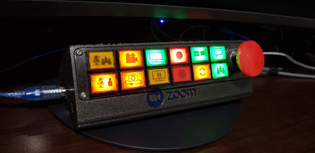
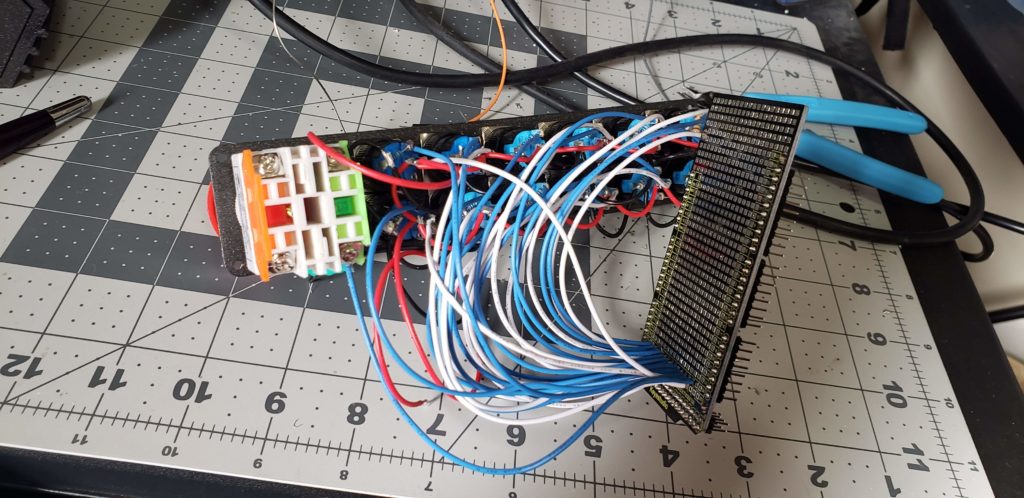
Today with most people working from home using teleconferencing applications, a custom control panel for such interactions could come in handy. This inspired professor Elena Long to design her own Zoom interface around on an Arduino, a 3D-printed enclosure, and a series of pushbuttons that allow for custom printed icons.
Long’s device features 12 main buttons — five momentary, seven latching. These are wired to light up via LEDs. There’s also large red mushroom button on the end provides a final latching input, which is perfect for aborting calls with a flourish.
Whereas many would assume the console is powered by either a Leonardo or Micro, Long’s unit is actually based on a Mega set up with the HoodLoader2 bootloader that enables it to act as a virtual keyboard.
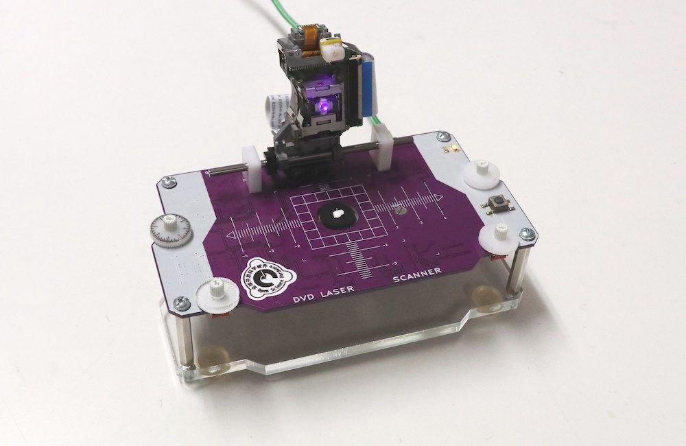
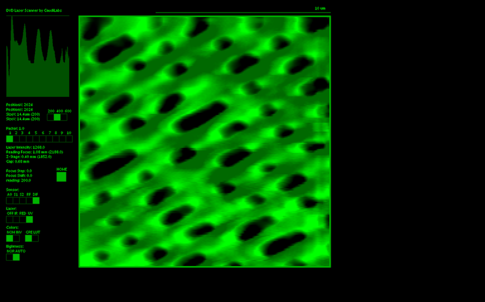
Laser scanning microscopes use a focused laser beam to scan tiny samples down to the sub-cellular level. As such, they are generally available as expensive lab implements. You might also consider that CDs drives – and even more so DVDs and Blu-ray players – must be able to focus laser beams down to incredibly small resolutions in order to read disc information off of tiny pits.
Microengineer Urs Gaudenz leveraged the capabilities of these readily available drives to create his own open source DVD Laser Scanner Microscope. His build employs a pair of pickup heads, one to emit the laser and scan in the x direction, and another to move the sample in the y direction.
The pickup head coils and laser current are controlled by an Arduino Micro, while Processing is used to visualize images for some really incredible closeups. More details along with code and schematics can be found on GitHub.
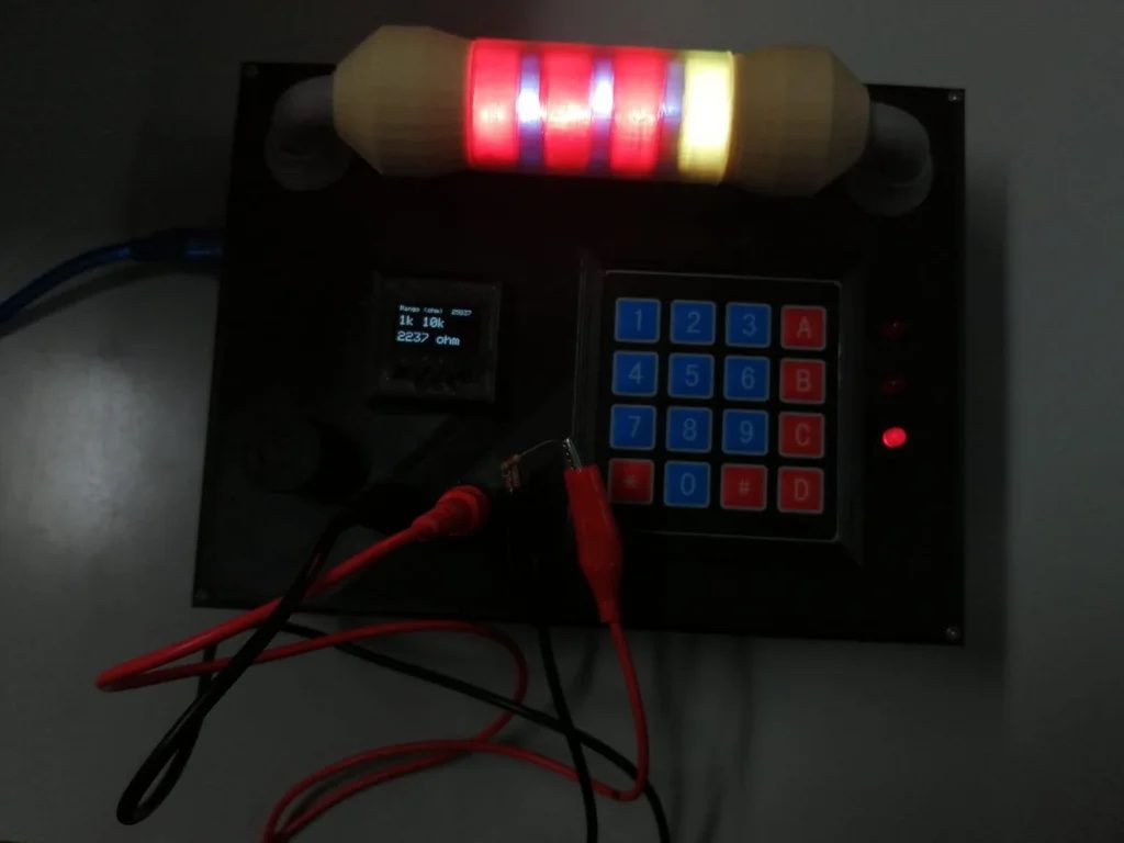
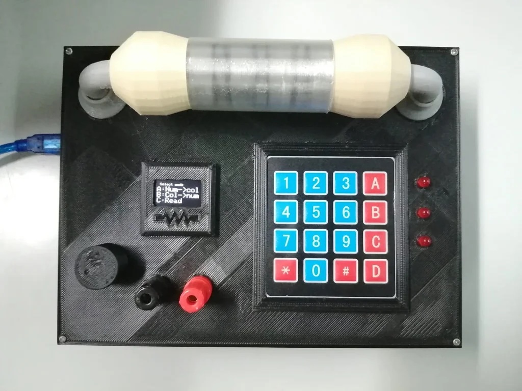
Bands on through-hole resistors conveniently indicate their value at a glance. On the other hand, you have to actually know the code to interpret this meaning. Alternatively, you could use the Ohmmeter 2.0 — developed by Miguel Alejandro Ramírez Anaya and José Miguel Galeas Merchán from the University of Málaga in Spain.
Their Arduino Mega-powered device has three modes. First, it enables you to enter resistor value with a keypad and then displays the corresponding resistor colors on a large resistor model via RGB LEDs inside. You can also input the color values directly using the keypad along with a small OLED screen. Last but not least, the Ohmmeter 2.0 can even measure a component’s resistance through a pair of terminals, replicating color values on the 3D model.
You can find more details on the students’ Ohmmeter 2.0 here and see it in action below.
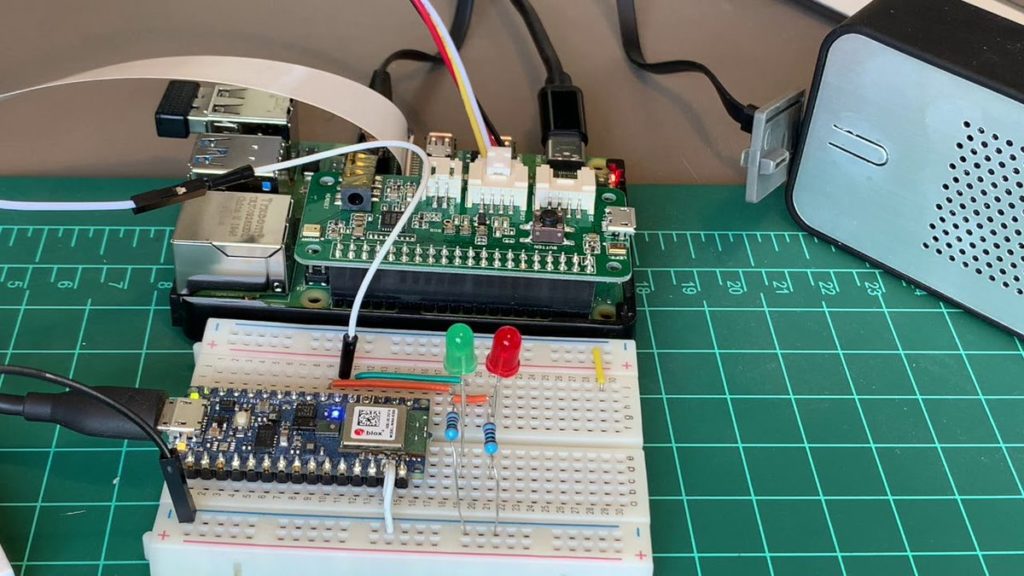
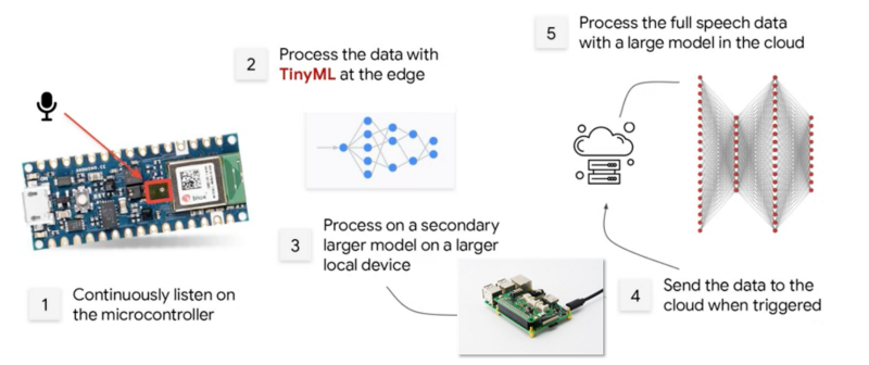
Smart speakers are amazing devices, able to answer a near-infinite array of questions, as well as offer a variety of AI services. As shown in this project write-up by Marcelo Rovai, you can emulate a Google Assistant with Raspberry Pi and ReSpeaker 2-Mics Pi HAT, which can be triggered to “wake” and respond to your voice queries with a physical button.
To take this system to the next level, he’s leveraging an Arduino Nano 33 BLE Sense that replaces the button with a virtual one through keyword spotting. The tinyML-enabled Nano then listens for “yes” using its onboard microphone. When activated, it sends a signal to the Raspberry Pi, which in turn processes subsequent requests via the Google Cloud.
Flip this DIY hourglass over and watch its LEDs fall like sand
Arduino Team — January 28th, 2021
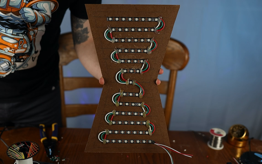
For centuries, hourglass instruments have been used to keep track of a certain amount of time. But while long superseded by other methods, this project by Ty and Gig Builds takes things full circle, creating an electronic version around WS2812B addressable LEDs.
The frame takes the form of a sort of 2D wooden hourglass, with RGB strips connected to snake from one end to another. An accelerometer reads whether the device is up or down, which passes orientation info to an Arduino Mega. The Mega in turn controls animations, simulating grains of sand as points of light dropping from the top section. As this happens, the bottom half incrementally fills with lit LEDs (as the top becomes dark), and the instrument can be again turned to reverse the process.
Added Virustotal scan to help users with false positives antivirus detections
We decided to uniform the naming to “Arduino Create Agent” and remove the mentions to “Plugin” or “Bridge”
If you are interested in the complete changelog, you can find that here.
For the upcoming releases, we will tackle the stability/crash problems. So please help us discover and find bugs by enabling crash report and including it in the GitHub issue.
Portenta Vision Shield now available with LoRa® module
Arduino Team — January 27th, 2021
What better way to announce the availability of the Portenta Vision Shield LoRa than at The Things Conference 2021, a global showcase for all the top-notch LoRaWAN products and services?
The LoRa® module option of the Portenta Vision Shield is specifically designed for edge ML applications, enabling low-power, long distance communication over LoRa® wireless protocol and LoRaWAN networks. It’s the perfect addition to the powerful Arduino Portenta H7 which makes possible machine learning on-device, thereby greatly reducing the communication bandwidth requirement in an IoT application.
Always-on machine vision: The Portenta Vision Shield comes with an ultra-low-power Himax camera. The camera module autonomously detects motion while the Portenta H7 is in stand-by — only waking up the microcontroller when needed.
Voice and audio event recognition: The Portenta Vision Shield features two ultra-compact and omnidirectional MP34DT06JTR microphones, bringing voice recognition and audio event detection. Both the video and audio data can be stored on an SD card, and transmitted through the LoRa® module to the Arduino IoT Cloud or your own infrastructure.
If you would like to learn how to createLoRa® powered solutions running machine vision algorithms, then watch Sebastian Romeo’s workshop at The Things Conference on Thursday, January 28th 1:00pm-1:30pm CET, followed by Q&A at 1:30pm CET. Save 20% off the price of entry to the conference, simply add this code when purchasing a ticket – TTC2021-FRIEND-OF-ARDUINO
The Portenta Vision Shield LoRa® is now available on the Arduino online store and you can learn more about Arduino’s participation in The Things Conference 2021 here.
Um dir ein optimales Erlebnis zu bieten, verwenden wir Technologien wie Cookies, um Geräteinformationen zu speichern und/oder darauf zuzugreifen. Wenn du diesen Technologien zustimmst, können wir Daten wie das Surfverhalten oder eindeutige IDs auf dieser Website verarbeiten. Wenn du deine Einwillligung nicht erteilst oder zurückziehst, können bestimmte Merkmale und Funktionen beeinträchtigt werden.
Funktional
Immer aktiv
Die technische Speicherung oder der Zugang ist unbedingt erforderlich für den rechtmäßigen Zweck, die Nutzung eines bestimmten Dienstes zu ermöglichen, der vom Teilnehmer oder Nutzer ausdrücklich gewünscht wird, oder für den alleinigen Zweck, die Übertragung einer Nachricht über ein elektronisches Kommunikationsnetz durchzuführen.
Vorlieben
Die technische Speicherung oder der Zugriff ist für den rechtmäßigen Zweck der Speicherung von Präferenzen erforderlich, die nicht vom Abonnenten oder Benutzer angefordert wurden.
Statistiken
Die technische Speicherung oder der Zugriff, der ausschließlich zu statistischen Zwecken erfolgt.Die technische Speicherung oder der Zugriff, der ausschließlich zu anonymen statistischen Zwecken verwendet wird. Ohne eine Vorladung, die freiwillige Zustimmung deines Internetdienstanbieters oder zusätzliche Aufzeichnungen von Dritten können die zu diesem Zweck gespeicherten oder abgerufenen Informationen allein in der Regel nicht dazu verwendet werden, dich zu identifizieren.
Marketing
Die technische Speicherung oder der Zugriff ist erforderlich, um Nutzerprofile zu erstellen, um Werbung zu versenden oder um den Nutzer auf einer Website oder über mehrere Websites hinweg zu ähnlichen Marketingzwecken zu verfolgen.