Schlagwort: 3d printing
-

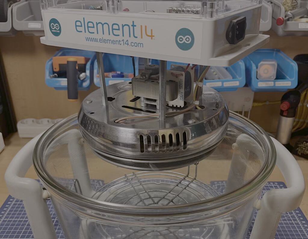
Convert a cheap air fryer into a high-performance 3D printer filament dryer
Reading Time: 2 minutesPost about a 3D printing problem — any 3D printing problem — online and all the top comments will be: “Is your filament dry?” That is a prudent question to ask, because filament that has absorbed moisture will wreak havoc on print quality and can even cause total print failure. If you…
-

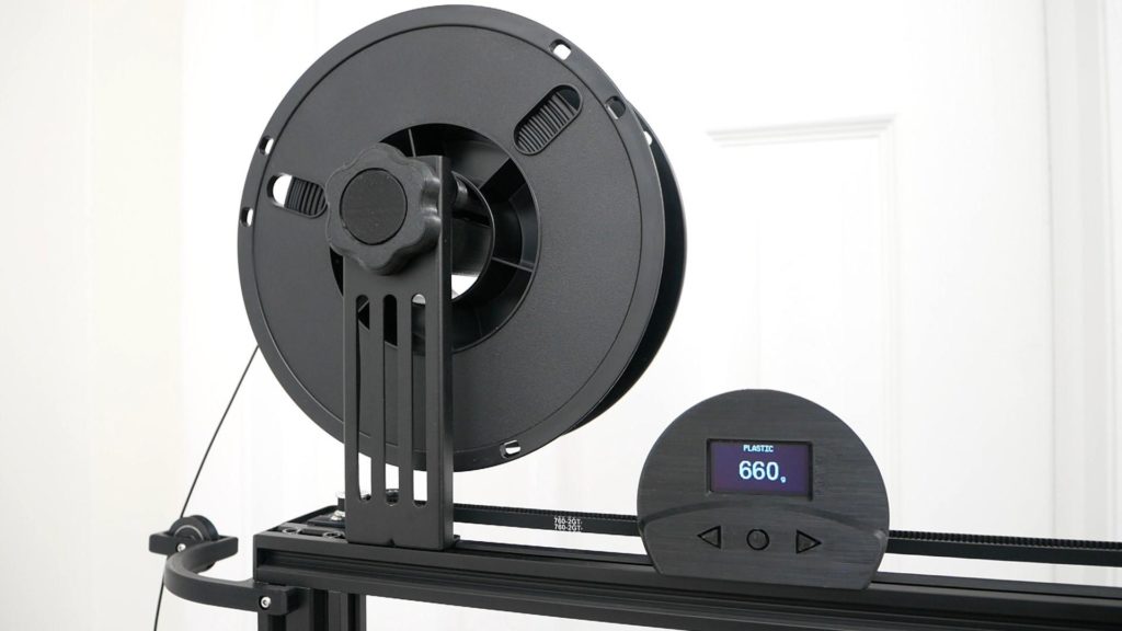
DIY digital spool scale tells you how much filament is left
Reading Time: 2 minutesWe’ve all been there: you’re about to start a new print job and the filament on the spool is looking pretty sparse. You start the print hoping that there is enough filament for the job, but it runs out 90% of the way through and your part is ruined. A filament runout…
-

Why using 3D printing in your smart home is so useful
Reading Time: 3 minutes3D printing, the stuff of science fiction only a few short years ago, is becoming more widely available all the time. Buying your own 3D printer to keep in your home is now fairly accessible, with entry-level printers available for just a few hundred dollars. But why would you buy one? It’s…
-

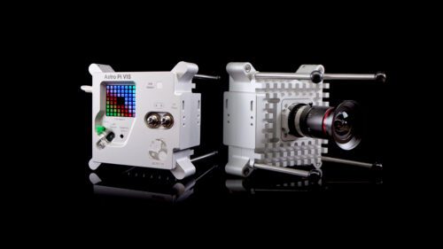
3D print you own replica Astro Pi flight case
Reading Time: 5 minutesWe’ve put together a new how-to guide for 3D printing and assembling your own Astro Pi unit replica, based on the upgraded units we sent to the International Space Station in December. The new, upgraded Astro Pi units. The Astro Pi case connects young people to the Astro Pi Challenge It wasn’t…
-

This overengineered robotic clock will not be underappreciated
Reading Time: < 1 minuteArduino Team — August 17th, 2021 Normally when an inexpensive wall clock stops ticking, you simply buy a new one. However, ‘Developer Hendrik’ decided to bring his broken clock back to life, or some semblance thereof, using a 3D-printed four-axis robot arm dubbed “Serworm Michael.” Under the control of a MKR 1010…
-
Holo Clock is a novel 3D-printed clock that tells time using a pair of rings
Reading Time: 2 minutesArduino Team — August 10th, 2021 Simply looking at a traditional analog clock sitting on a wall somewhere got pretty boring for one Instructables user who goes by saulemmetquinn, which is partially why they wanted to create a novel design instead. Their device uses almost entirely 3D-printed components that come together to…
-

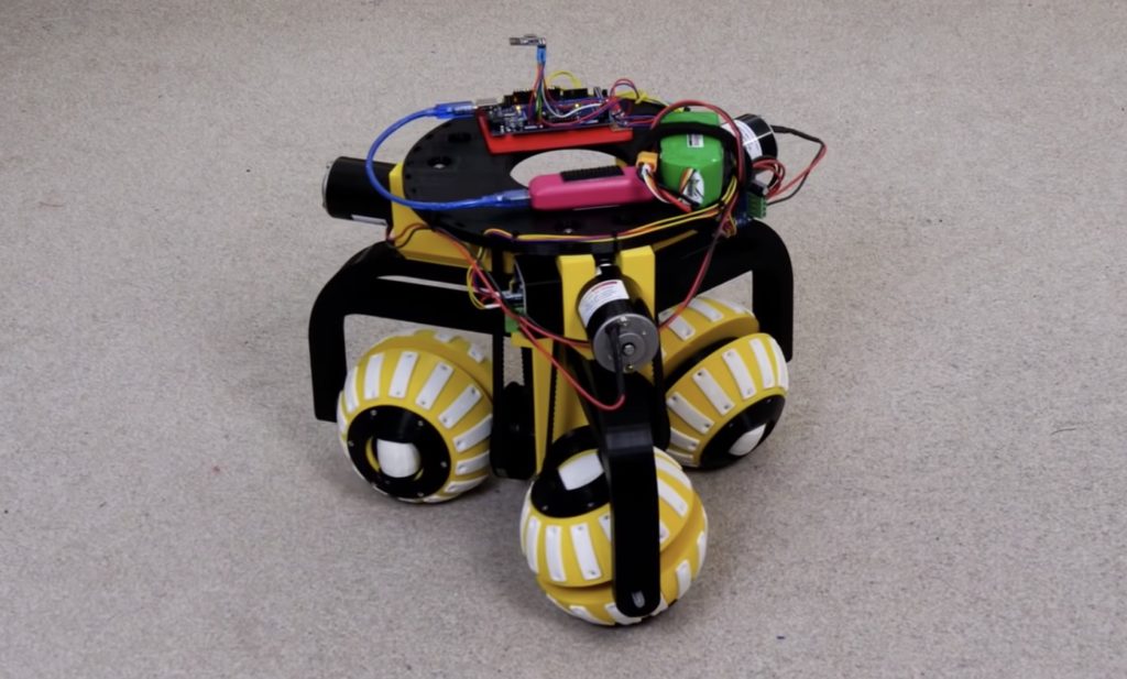
James Bruton’s robot uses three ball-shaped wheels to move in any direction
Reading Time: 2 minutesJames Bruton’s robot uses three ball-shaped wheels to move in any direction Arduino Team — June 5th, 2021 Wheeled robots normally have wheels that move in a single axis and steer by using either differential speeds or by pivoting some kind of guide wheel. However, this leads to some drawbacks, the most…
-

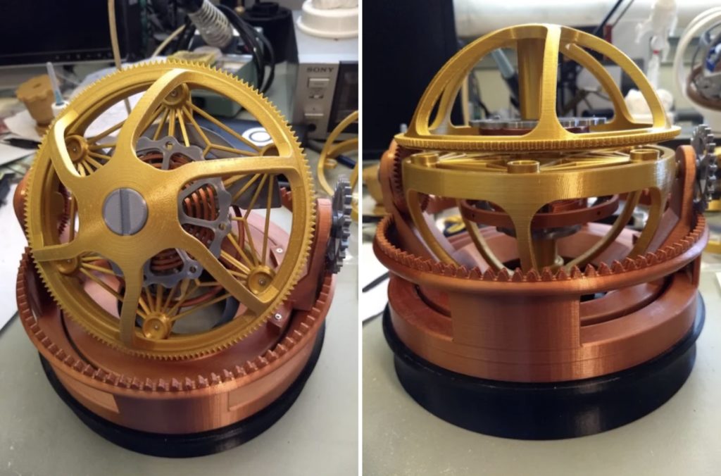
This 3D-printed tourbillon was modeled after Jacob & Co’s Twin Turbo Furious watch
Reading Time: 2 minutesThis 3D-printed tourbillon was modeled after Jacob & Co’s Twin Turbo Furious watch Arduino Team — June 1st, 2021 It seems like everyone who has a substantial net worth carries around a few luxury watches, but none are perhaps as mechanically enthralling as the Twin Turbo Furious watch from Jacob & Co.,…
-

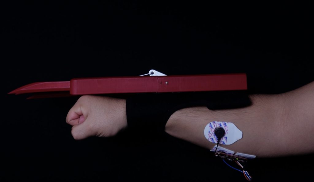
Channel your inner Wolverine with these 3D-printed, muscle-controlled bionic claws
Reading Time: < 1 minuteArduino Team — May 1st, 2021 In the fictional Marvel Universe, Wolverine has sets of claws that pop out of his hands as if they were natural parts of his body. While a seemingly fantastic concept, myoelectric sensors are able to pick up on muscle movements in order to illicit a…
-

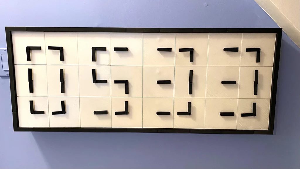
This digital clock uses 24 Arduino-controlled analog faces
Reading Time: < 1 minuteThis digital clock uses 24 Arduino-controlled analog faces Arduino Team — March 5th, 2021 After being inspired by a beautiful, if rather expensive timepiece, Ira Hart decided to make a 3D-printed clock with 24 analog faces that combine to form a single digital display. The overall device is controlled by a single…
-

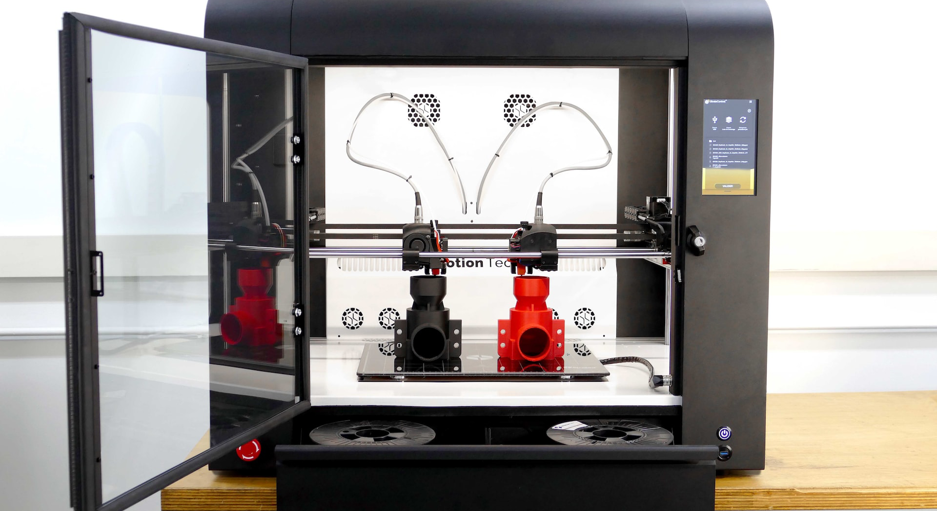
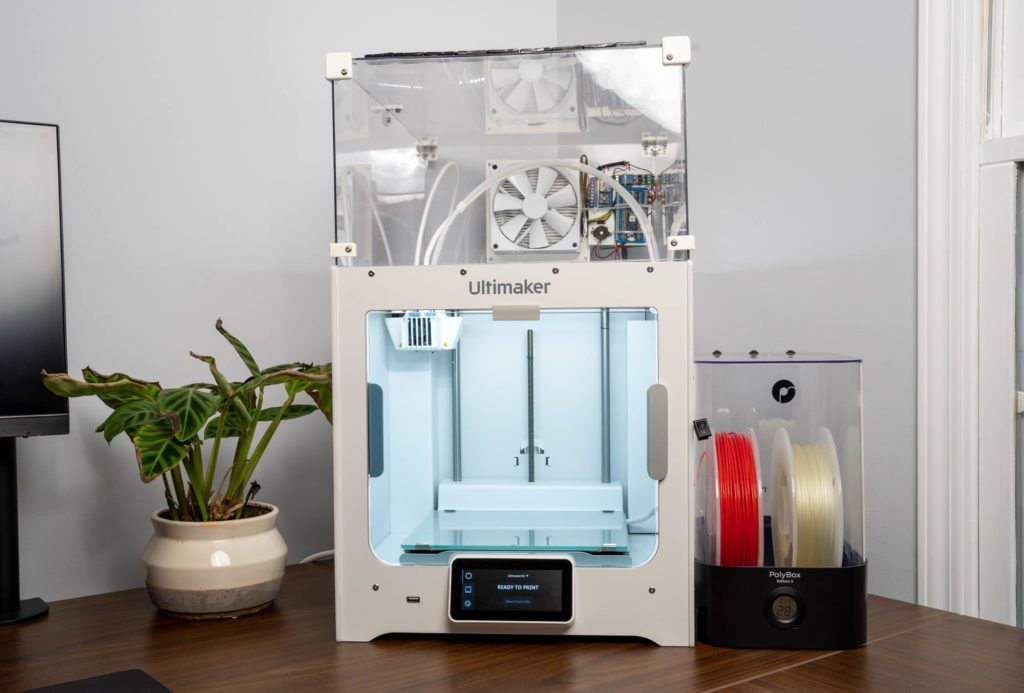
Create a Nano 33 IoT-based filtration and flame detection system for your 3D printer
Reading Time: 2 minutesCreate a Nano 33 IoT-based filtration and flame detection system for your 3D printer Arduino Team — January 8th, 2021 After welcoming a new child into the world, Mike Buss decided that his 3D printer needed a few safety enhancements. To address this issue, he added a clear chamber on top of his…
-

Making a mini 360° LiDAR for $40
Reading Time: 2 minutesMaking a mini 360° LiDAR for $40 Arduino Team — December 21st, 2020 LiDAR (or “light detection and ranging”) sensors are all the rage these days, from their potential uses in autonomous vehicles, to their implementation on the iPhone 12. As cool as they are, these (traditionally) spinning sensors tend to be…
-

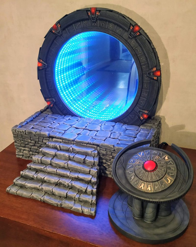
The Stargate | The MagPi 101
Reading Time: 4 minutesFans of the Stargate SG-1 series, prepare to be inspired: a fellow aficionado has fashioned his own model of the show’s iconic portal. Nicola King takes an interstellar trip in the latest issue of The MagPi Magazine. When Kristian Tysse began making some projects on his new 3D printer, he soon became…
-

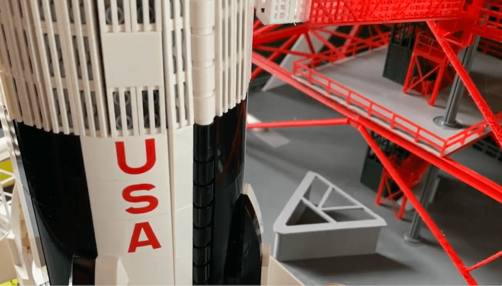
A fully-animated, Arduino-powered launchpad for the LEGO Saturn V model rocket
Reading Time: 2 minutesA fully-animated, Arduino-powered launchpad for the LEGO Saturn V model rocket Arduino Team — December 16th, 2020 Approximately 18 months ago, Mark Howe embarked on a journey to build an animatronic launchpad and gantry for a LEGO Saturn V model rocket. After approximately 1,000 hours of CAD work, hundreds of hours of…
-

3D-printed Super Mario star twinkles atop the tree
Reading Time: < 1 minute3D-printed Super Mario star twinkles atop the tree Arduino Team — December 11th, 2020 Christmas trees normally have a star on top, and Super Mario famously becomes invincible when he grabs the star power-up. Naturally, for retro game enthusiasts, these two are begging to be united. In this project, Doug Lenz…
-
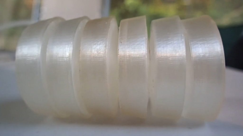
This Arduino-controlled soft robot gets around like an earthworm
Reading Time: < 1 minuteThis Arduino-controlled soft robot gets around like an earthworm Arduino Team — September 28th, 2020 After studying the way a worm wiggles, Nicholas Lauer decided to create his own soft robotic version. What he came up with uses an Arduino Uno for control, inflating six 3D-printed segments sequentially to order to…
-

These geodesic RGB LED spheres are absolutely stunning
Reading Time: < 1 minuteThese geodesic RGB LED spheres are absolutely stunning Arduino Team — September 21st, 2020 While this project took him over 100 hours to complete, creator Whity claims that his glowing geodesic domes were worth the effort. As seen below, each dome is able to light up its triangular faces, using via…
-

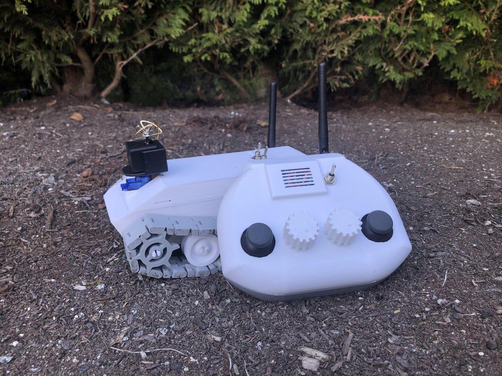
Explore the backyard and beyond with this FPV RC vehicle
Reading Time: < 1 minuteExplore the backyard and beyond with this FPV RC vehicle Arduino Team — September 14th, 2020 If you want to build your own first-person view RC rover for some backyard exploration, this design by “MoreMorris” is a great place to start. The tank-esque vehicle features a 3D-printed frame, including print-in-place tracks,…
-

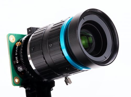
3D-printable cases for the Raspberry Pi High Quality Camera
Reading Time: 4 minutesEarlier this year, we released the Raspberry Pi High Quality Camera, a brand-new 12.3 megapixel camera that allows you to use C- and CS-mount lenses with Raspberry Pi boards. We love it. You love it. How do we know you love it? Because the internet is now full of really awesome 3D-printable…
-

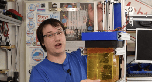
New twist on Raspberry Pi experimental resin 3D printer
Reading Time: 3 minutesElement14’s Clem previously built a giant Raspberry Pi-powered resin-based 3D printer and here, he’s flipped the concept upside down. The new Raspberry Pi 4 8GB reduces slicing times and makes for a more responsive GUI on this experimental 3D printer. Let’s take a look at what Clem changed and how… [youtube https://www.youtube.com/watch?v=3rttZ-59ZAo?feature=oembed&w=500&h=281]…
-

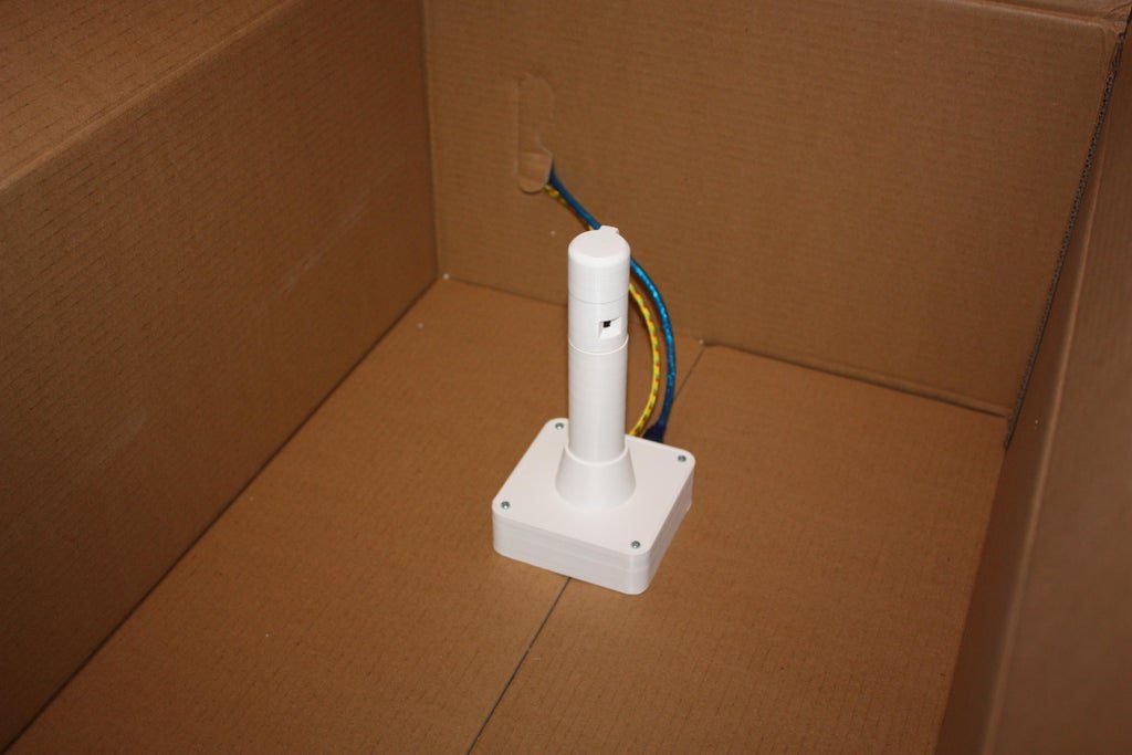
Arduino X-ray imaging phantom simulates lung movement
Reading Time: < 1 minuteArduino X-ray imaging phantom simulates lung movement Arduino Team — August 5th, 2020 Imaging phantoms are used to evaluate and test medical devices, such as X-ray machinery, where a human subject would be impractical and/or dangerous. In order to simulate the motion and deformation of a lung, Stefan Grimm created an…
-

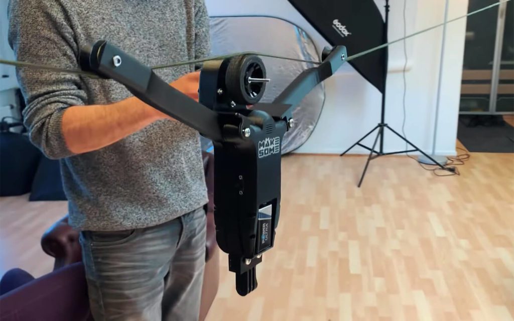
DIY cable cam made from RC car and 3D-printed parts
Reading Time: < 1 minuteDIY cable cam made from RC car and 3D-printed parts Arduino Team — July 14th, 2020 Cable-mounted cameras can be a lot of fun for capturing moving footage. Although commercial cable cam options can be expensive, this system by Kasper Mortensen of MAKESOME is comprised of 3D-printed components with a receiver and…