Kategorie: Linux

  • Learn SQL and database design with Raspberry Pi

    Learn SQL and database design with Raspberry Pi

    Reading Time: 3 minutes

    SQLite

    SQLite’s site is basic, but sqlitetutorial.net provides free interactive training. As well as covering SQL for SQLite (all platforms have slightly different implementations of SQL), there is a Python-specific course. Here, you can learn how to use PySQLite, the Python bindings for SQLite. Not only is the SQL language covered, but how to create databases and tables in Python. This makes for a comprehensive combination of courses.

    MariaDB

    MariaDB/MySQL

    The next logical step from SQLite is to move to a full relational database server. A popular choice is MariaDB, an open-source project based on, and fully compatible with, MySQL. MySQL is probably one of the most popular database servers of all time. Both variants are free, but MariaDB boasts a new ‘engine’ that provides significant speed increases. Installing the server is straightforward and it runs surprisingly fast, even on older Raspberry Pi hardware. Once installed, you’ve more to think about than with SQLite, such as users and permissions. Thankfully, MariaDB offers online courses for free – a nicer way to learn than ploughing through dry documentation. This is a powerful platform: it can take tables containing millions of rows in its stride. It’s possible to use MariaDB/MySQL for anything from your own logging project, to enterprise-grade applications.

    MongoDB

    MongoDB

    Certain applications or projects require a different type of database. If you’re looking at storing lots and lots of simple data and don’t require the kind of data extraction that relational databases offer, then a NoSQL (or document) database may be for you. This family of databases specialise in high-volume, fast data storage and retrieval. They are especially popular when the job is to ‘just get the data and store it as quickly as possible’. Rather than using the traditional model of tables, columns, and rows, document databases use schemas and key-pairs to store data. MongoDB is a popular open-source server. It’s very easy to install, and you can undertake a full course.

    The Definitive Guide to SQLite

    Grant Allen and Michael Owen’s book on SQLite is a comprehensive look at this ‘micro’ database. Despite its small footprint, the authors reveal an incredibly powerful engine and some surprising applications including embedded systems.

    MySQL for Python

    Python being the preferred choice of language of the Raspberry Pi Foundation, this book is a perfect introduction to using Python’s MySQL wrappers. The MySQL for Python book is formatted as a series of tutorials that increase with complexity.

    MongoDB and Python

    Like the aforementioned MySQL for Python book, this one gets right to the point. It uses the ‘recipe’ format, so you can find a close match for the problem you want to solve, and see how using MongoDB can help.

    Udemy SQL Video courses

    Intro To SQLite Databases for Python Programming

    A great ‘back to basics’ video course which takes you through all the steps of installing and using SQLite. Intro to SQLite Databases for Python Programming is 90 minutes of video in bite-size pieces.

    Using MySQL Databases With Python

    Just like for SQLite, Udemy offers a full nothing-to-something course on using MySQL Databases with Python. The two hours of video usefully cover installation of the server.

    MongoDB and Python: Quick start

    Crucially, this MongoDB and Python: Quick Start two-hour video course covers when to choose a NoSQL (or document) database and the key differences between this and traditional SQL engines.

  • Building a split mechanical keyboard with a Raspberry Pi Zero controller

    Building a split mechanical keyboard with a Raspberry Pi Zero controller

    Reading Time: 3 minutes

    Looking to build their own ergonomic mechanical split keyboard, Gosse Adema turned to the Raspberry Pi Zero W for help.

    So long, dear friend

    Gosse has been happily using a Microsoft Natural Elite keyboard for years. You know the sort, they look like this:

    Twenty years down the line, the keyboard has seen better days and, when looking for a replacement, Gosse decided to make their own.

    This is my the first mechanical keyboard project. And this will be for daily usage. Although the possibilities are almost endless, I limit myself to the basic functionality: An ergonomic keyboard with mouse functions.

    Starting from scratch

    While searching for new switched, Gosse came across a low-profile Cherry MX that would allow for a thinner keyboard. And what’s the best device to use when trying to keep the profile of your project as thin as possible? Well, hello there, Raspberry Pi Zero W, aren’t you looking rather svelte today.

    After deciding to use a Raspberry Pi as the keyboard controller over other common devices, Gosse took inspiration from an Adafruit tutorial on turning Raspberry Pi into a USB gadget, and from “the usbarmory Github page of Chris Kuethe”, which describes how to create a USB gadget with a keyboard.

    Build your own

    There is a lot *A LOT* of information on how Gosse built the keyboard on Instructables and, if we try to go into any detail here, our word count is going to be in the thousands. So, let’s just say this: the project uses some 3D printing, some Python code, and some ingenuity to create a lovely-looking final keyboard. If you want to make your own, Gosse has provided absolutely all the information you need to do so. So check it out, and be sure to give Gosse some love via the comments section on Instructables.

    Mechanical keyboards

    Also, if you’re unsure of how a mechanical keyboard differs from other keyboards, we made this handy video for you all!

    How do mechanical keyboards work?

    So, what makes a mechanical keyboard ‘mechanical’? And why are some mechanical keyboards more ‘clicky’ than others? Custom PC’s Edward Chester explains all. …

    Website: LINK

  • Designing a low-cost, open source ventilator with Arduino

    Designing a low-cost, open source ventilator with Arduino

    Reading Time: < 1 minute

    Designing a low-cost, open source ventilator with Arduino

    Arduino TeamMarch 17th, 2020

    Desperate times call for desperate measures, and while making your own medical equipment isn’t normally advisable, Johnny Lee’e project explores how to turn a CPAP machine into a ventilator.

    The idea is that since these machines are basically just blowers controlled by a brushless DC motor, an Arduino Nano equipped with an electonic speed controller could allow it to act as a one.

    Such a setup has been shown to provide more than enough pressure for a ventilator used on COVID-19 patients. This device has in no way been evaluated or approved for medical use, but it does provide a starting point for experimentation.

    You can find additional details on Lee’s GitHub page.

    Website: LINK

  • Wireframe’s deep(ish) dive into the glorious double jump

    Wireframe’s deep(ish) dive into the glorious double jump

    Reading Time: 2 minutes

    Yoshi aside, we can’t think of anyone who isn’t a fan of the double jump. In their latest video, the Wireframe magazine team take a deep(ish) dive into one of video gaming’s most iconic moves.

    What is the Double Jump | Wireframe Deep Dive

    The humble jump got a kick in 1984 with the introduction of the double jump, a physicist’s worst nightmare and one of video gaming’s most iconic moves. Subsc…

    Also, HDR!

    Are you looking to upgrade your computer monitor? Last week, Custom PC magazine, a publication of Raspberry Pi Press, released their latest video discussing HDR monitors. Are you ready to upgrade, and more importantly, should you?

    What is an HDR monitor? High dynamic range explained | Custom PC magazine

    High dynamic range (HDR) monitors are all the rage, but what exactly is HDR and which monitors produce the best image quality? Check out our full HDR guide: …

    We produce videos for all our Raspberry Pi Press publications, including magazines such as The MagPi and HackSpace magazine, as well as our book releases, such as Code the Classics and Build Your Own First-Person Shooter in Unity.

    Subscribe to the Raspberry Pi Press YouTube channel today and click on the bell button to ensure you’re notified of all new releases. And, for our complete publication library, visit the Raspberry Pi Press online store.

    Website: LINK

  • Using an Arduino/CNC shield setup for ham radio control

    Using an Arduino/CNC shield setup for ham radio control

    Reading Time: < 1 minute

    Using an Arduino/CNC shield setup for ham radio control

    Arduino TeamMarch 16th, 2020

    Loop antennas for ham radios use heavy duty variable capacitors for tuning. Since such capacitors need to be physically turned for adjustment, radio enthusiast Jose B.O. made his own remote rig using an Arduino Uno and CNC shield.

    The CNC setup allows stepper motors to rotate through a range of angles for frequency selection, and three antennas can be controlled via separate Pololu A4988 driver modules. An optical encoder is used for control, along with buttons for preset frequencies, and a 16×2 I2C LCD display provides visual feedback. Microswitches are implemented to set the upper and lower bounds for the stepper motors.

    More info is available in the project’s write-up and the videos below show the system in action.

    [youtube https://www.youtube.com/watch?v=od0Ufq2bn04?feature=oembed&w=500&h=375]

    [youtube https://www.youtube.com/watch?v=7ItA2ri0BPo?feature=oembed&w=500&h=281]

    Website: LINK

  • Thales, Telstra, Microsoft and Arduino deliver scalable trust for easy-to-deploy IoT Applications

    Thales, Telstra, Microsoft and Arduino deliver scalable trust for easy-to-deploy IoT Applications

    Reading Time: 2 minutes

    We’ve partnered with Thales, Telstra and Microsoft to pave the way for scalable security for connected IoT devices, by implementing a solution that enables trusted and secure end-to-end communication between device and cloud.

    The solution enables instant and standardized mutual authentication between a device and a cloud platform via cellular networks, while fully-complying with GSMA IoT SAFE security specifications.

    Within the IoT ecosystem, billions of devices collect, process and send data to the cloud, where a range of different IoT services are executed. To enable security, the IoT cloud service must have absolute trust in data received from connected devices. Equally, devices need to trust the cloud. This is only possible if the device and server are mutually authenticated. However, the IoT devices market is so fragmented — with a patchwork of different operating systems and chips being utilized — that security services scalability and duplication are very limited.

    That’s why Thales, Telstra, Microsoft[1]and Arduino[2] have decided to team up to work on a solution that addresses the challenge of securely and efficiently connecting IoT devices to clouds in the most simplified way and through cellular networks. The level of trust required is enabled by a sophisticated ‘security-by-design’ approach for any IoT devices based on field-proven and standardized SIM or eSIM technology.

    As a result, as soon as an IoT device is switched on, any SIM or eSIM featuring Thales’s IoT SAFE application is automatically and securely provisioned. Once the IoT device gets a proper Digital Certificate created and stored in the SIM/eSIM, then a trusted communication between the device and the server is permitted, in full respect of data integrity and confidentiality.  

    We are very pleased to be part of the dream team composed by Thales, Telstra and Microsoft,” said Fabio Violante, Arduino CEO. “The development of this tool was a teamwork and a proof that Arduino is a great partner to create solid, reliable and easy to integrate hardware and software IoT solutions.

    [1] Microsoft integrated the IoT SAFE solution with their Azure IoT Hub and also provided Azure Stream Analytics, Cosmos DB and Power BI services to quickly enable the development of an example end-to-end IoT application.

    [2] We developed a library (under an open source license) that implements the security mechanism of the GSMA IoT Safe standard on our MKR NB 1500 boards and provides a valid alternative to the usage of the crypto chip already present on the Arduino board. The project has been a great example of collaborations with companies operating in various IoT sectors through our brand new Arduino Pro division.

    Website: LINK

  • NexDock 2 review

    NexDock 2 review

    Reading Time: 2 minutes

    And what a lovely screen it is: the 13.3-inch IPS 1920×1080 display is a delight to look at, even if the chunky borders are a bit retro. The edge-to-edge full-sized backlit keyboard is equally impressive, with responsive chiclet-style keys that are suitably clicky. Typing is a breeze.

    The whole thing is set off in a grey and black style that’s far more professional than its price tag warrants.

    And we’re trying hard to ignore the unfortunate bulge in the plastic hinge above our F2 key. Perhaps we got an early run that slid through the checks.

    Battery life

    Inside NexDock 2 sits a 51 Wh battery that provides power to the screen and keyboard and Raspberry Pi. We ran our fully charged unit with Raspberry Pi 4 playing YouTube videos from 10:10 to 15:22, just over five hours of solid playback.

    A supplied 60 W USB-C adapter is used for charging.

    Plugging in

    In the box is an HDMI cable with a micro-HDMI to HDMI adapter for Raspberry Pi 4. Meanwhile, a USB-C cable splits out to USB-A and micro-USB (for power and keyboard/mouse connection). That’s a lot of cabling compared to a regular laptop. The nest of cables is an issue.

    We managed to bend the connection on the HDMI-to-micro-HDMI adapter, and replaced it with the white extension cable (pictured above). Be sure to disconnect everything when you pack up.

    Achilles’ trackpad

    The weakest link is the trackpad. There’s no thumb rejection – so as you type, the cursor jumps around the screen. And if you use a thumb to click, the cursor jumps from the clicked point.

    Our solution is to attach a USB and disable the trackpad with xinput:

    xinput --set-prop "SINO WEALTH USB KEYBOARD Mouse" "Device Enabled" 0

    To re-enable the trackpad:

    xinput --set-prop "SINO WEALTH USB KEYBOARD Mouse" "Device Enabled" 1

    The lack of hardware and software integration soon becomes apparent. Closing the screen shuts off the power to the display, but not immediately to Raspberry Pi, which carries on running for a short time until the power is yanked. We took to using shutdown -h now when done and removing all the cables.

    Digital nomad

    Using Raspberry Pi with NexDock 2 as your go‑to laptop is stretching credibility. The finicky trackpad, nest of wires and dongles, and lack of creature comforts will drive you round the bend.

    However, NexDock 2 is ideal for users who need to power up a Raspberry Pi at an event. We imagine Pi Jam-goers and folks at Pi Wars will find NexDock 2 a very handy device to have around.

    Verdict

    8/10

    An incredibly useful, yet far from perfect, solution to using Raspberry Pi on the move. Despite its flaws, it is, by far, the best solution we have found to this particularly thorny problem.

  • Recreate Flappy Bird’s flight mechanic | Wireframe #29

    Recreate Flappy Bird’s flight mechanic | Wireframe #29

    Reading Time: 3 minutes

    From last year’s issue 29 of Wireframe magazine: learn how to create your own version of the simple yet addictive side-scroller Flappy Bird. Raspberry Pi’s Rik Cross shows you how.

    Flappy Bird: ridiculously big in 2014, at least for a while.

    Flappy Bird was released by programmer Dong Nguyen in 2013, and made use of a straightforward game mechanic to create an addictive hit. Tapping the screen provided ‘lift’ to the main character, which is used strategically to navigate through a series of moving pipes. A point is scored for each pipe successfully passed. The idea proved so addictive that Nguyen eventually regretted his creation and removed it from the Google and Apple app stores. In this article, I’ll show you how to recreate this simple yet time-consuming game, using Python and Pygame Zero.

    The player’s motion is very similar to that employed in a standard platformer: falling down towards the bottom of the screen under gravity. See the article, Super Mario-style jumping physics in Wireframe #7 for more on creating this type of movement. Pressing a button (in our case, the SPACE bar) gives the player some upward thrust by setting its velocity to a negative value (i.e. upwards) larger than the value of gravity acting downwards. I’ve adapted and used two different images for the sprite (made by Imaginary Perception and available on opengameart.org), so that it looks like it’s flapping its wings to generate lift and move upwards.

    Pressing the SPACE bar gives the bird ‘lift’ against gravity, allowing it to navigate through moving pipes.

    Sets of pipes are set equally spaced apart horizontally, and move towards the player slowly each frame of the game. These pipes are stored as two lists of rectangles, top_pipes and bottom_pipes, so that the player can attempt to fly through gaps between the top and bottom pipes. Once a pipe in the top_pipes list reaches the left side of the screen past the player’s position, a score is incremented and the top and corresponding bottom pipes are removed from their respective lists. A new set of pipes is created at the right edge of the screen, creating a continuous challenge for the player. The y-position of the gap between each newly created pair of pipes is decided randomly (between minimum and maximum limits), which is used to calculate the position and height of the new pipes.

    The game stops and a ‘Game over’ message appears if the player collides with either a pipe or the ground. The collision detection in the game uses the player.colliderect() method, which checks whether two rectangles overlap. As the player sprite isn’t exactly rectangular, it means that the collision detection isn’t pixel-perfect, and improvements could be made by using a different approach. Changing the values for GRAVITY, PIPE_GAP, PIPE_SPEED, and player.flap_velocity through a process of trial and error will result in a game that has just the right amount of frustration! You could even change these values as the player’s score increases, to add another layer of challenge.

    Here’s Rik’s code, which gets an homage to Flappy Bird running in Python. To get it working on your system, you’ll first need to install Pygame Zero. And to download the full code, go here.

    If you’d like to read older issues of Wireframe magazine, you can find the complete back catalogue as free PDF downloads.

    The latest issue of Wireframe is available in print to buy online from the Raspberry Pi Press store, with older physical issues heavily discounted too. You can also find Wireframe at local newsagents, but we should all be staying home as much as possible right now, so why not get your copy online and save yourself the trip?

    Make sure to follow Wireframe on Twitter and Facebook for updates and exclusive offers and giveaways. And subscribe on the Wireframe website to save up to 49% compared to newsstand pricing!

    Website: LINK

  • How the Raspberry Pi Foundation is responding to the novel coronavirus

    How the Raspberry Pi Foundation is responding to the novel coronavirus

    Reading Time: 4 minutes

    In this blog post, I want to share an update on how the Raspberry Pi Foundation is responding to the novel coronavirus and what it means for our work to support people all over the planet to change their world through technology.

    The situation is changing rapidly, and we’ll update this blog as our response develops.

    Follow local public health advice

    The main guidance to our teams, partners, and community members is that they should follow the local public health advice in the country or region where they are based.

    The spread of the virus is at different stages in different parts of the world. That’s one reason why the public health advice differs so much depending on where you are. This is a new threat and there are competing theories about the best course of action. We see that in the different approaches that are being taken by different governments around the world.

    To state what I am sure is obvious, we aren’t epidemiologists or public health experts. That’s why our approach is to follow the local public health advice.

    Changes to our schedule of events

    We’ve been working closely with venues, partners, sponsors, and community members to keep our programme of events under review. There aren’t currently any restrictions on events that affect the specific dates and places where our events are being held. The problem really is one of uncertainty.

    Until now, we’ve taken a ‘wait and see’ approach for events, following the local public health guidance closely and working on the assumption that we will go ahead as planned, unless the local advice is to cancel. However, over the past couple of days, we have become increasingly concerned that we are asking people to book travel and make practical arrangements when we think that there is a high likelihood that we will have to cancel events at the last minute.

    We have therefore taken a number of very difficult decisions about our events programme.

    Cambridge Computing Education Research Symposium, 1 April 2020

    We have decided to hold the Research Symposium as an online-only event. Plans for this are well developed, and we are looking forward to bringing together an amazing community of researchers, academics, and practitioners to discuss cutting-edge research on how young people learn computing and computer science. Registration remains open and we will provide updates on the event via the symposium web page.

    Coolest Projects UK, 4 April 2020 in Manchester, and Coolest Projects International, 6 June 2020 in Dublin

    We have decided to cancel both upcoming Coolest Projects events. This was a really tough decision. In both cases, there is just too much uncertainty for us to continue to ask young people, parents, mentors, and volunteers to make travel and other arrangements. We are exploring options for providing an online experience that will enable the young creators to still showcase their amazing projects, so please don’t stop work on your project. We will provide further updates on the Coolest Projects website.

    Clubs and community-led events

    We have issued guidance to the tens of thousands of brilliant human beings that organise Code Clubs, CoderDojos, Raspberry Jams, and other community-led events all over the world. Our message is that they should follow the local public health advice in their country or region and take decisions on whether to cancel their club or event in consultation with the venues that host them. If you are a club leader or an event organiser and you have a concern, please contact us in the usual way, or email us at [email protected]

    We are working with community members and partners to increase our support for online learning, and we’ll say more about this soon. For now, clubs (and everyone else) can access all of our free learning resources online as usual.

    Raspberry Pi computers

    As a organisation with a global supply chain that makes and sells products all over the world, we have been working with our partners to minimise the impact of the pandemic on the availability of our products, and on the wellbeing of those involved in our supply chain and distribution network. At this stage, I am delighted to report that Raspberry Pi products are still available in all of the usual places and we’re working very hard to make sure that this continues.

    Supporting colleagues

    We have implemented a range of actions to support our colleagues wherever they work. This has included restricting non-essential international travel, encouraging and supporting flexible and home working, improving the cleaning and hygiene facilities at our offices, and putting in place extra support for colleagues who have increased caring responsibilities because of government or other institutions taking actions to control the spread of the virus, like school closures.

    We are following local public health guidance on self-isolation and, for anyone who is unwell, we will provide sick pay as normal. We have committed that none of our employees will be out of pocket because of actions we take to prevent the spread of the virus.

    We have encouraged colleagues to consider moving face to face meetings online, including job interviews. So if you’re due to meet anyone at the Foundation, they’ll check in with you about your preferences and agree the best approach with you.

    Look out for each other

    One of the best things about Raspberry Pi is the amazing community that we have the privilege to work with everyday. That includes our teams, partners and funders, educators, volunteers, businesses, and millions of incredible young digital makers.

    Whatever happens over the coming days, weeks, and months, it feels increasingly likely that everyone in this community will be affected in some way. Hopefully, for most people that will be nothing more than being inconvenienced.

    Personally, I am finding the uncertainty one of the hardest things to deal with. I’ve really appreciated all of the messages of support and offers of help that I’ve received over the past few days. This has always been an organisation and a community where people genuinely care about and support each other. Let’s all double down on that now.

    Philip Colligan

    CEO Raspberry Pi Foundation

    Website: LINK

  • Arduino CLI: An introduction

    Arduino CLI: An introduction

    Reading Time: 3 minutes

    It’s been a long time since we first launched our Arduino IDE inspired by the glorious Processing interface, and what started as a Java UI wrapper for build scripts has gone through countless iterations over the past fifteen years.

    Some may remember the transition between 1.0 and 1.5, or the application’s icon being replaced, but behind the scenes where many of our users don’t go look, we’ve completely overhauled the way libraries are included, code is cleaned, fail-safe measures are implemented, and a sketch is built.

    At the same time our more advanced users have been implementing workarounds to use our internal builder command in their workflows for the most diverse reasons.

    Projects have spawned to create Arduino-based makefiles, build scripts, code linters ,and snippets to program their boards using their favorite code editors, and we’ve seen people use Eclipse, Sublime Text, VS Code, Vi(m), Emacs, or even XCode to create Arduino projects.

    We keep our eyes peeled when it comes to how our community uses our tools and try as much as possible to learn from it, and this inspired us to get back to the drawing board.

    The software that makes up the Arduino platform has grown incrementally over time — new features were added and sometimes the need to quickly factor in those changes did not make it easy to foresee how things would develop years ahead. This led to a situation in which multiple chunks of code and functionalities were spread across different Arduino software products (the Java IDE, the Create Agent, the Web Editor servers, upload/discovery tools, etc.), some of them overlapping or redundant. 

    The needs of our community, as well as our own, prompted us to radically rethink our approach and embark on a major refactoring operation with the goal to obtain a single reference implementation: the Arduino Command Line Interface.

    As we move forward, all our legacy products are being reworked to use the Arduino CLI as the foundation to build upon.

    We believe this effort will provide our users and ourselves with more advanced, flexible tools that we can all benefit from.

    How it started

    Following an extended period of internal use and exploration, we announced the Arduino CLI alpha preview in August 2018.

    From that moment on we concentrated our efforts into adding features, smoothing out some edges, and improving the CLI usability, largely based on users’ feedback from within our community (check out our latest release on GitHub).

    A tool to enable advanced workflows

    Having a flexible yet simple command line tool providing all the features and flexibility that made Arduino a successful platform can enable users to find new ways of improving their productivity. A great example is how Arduino CLI has been used in Continuous Integration processes, a great example of which came from our friends at TensorFlow, a popular open source machine learning framework. This encouraged us to provide an official Arduino CLI GitHub Action.

    This application demonstrates how the Arduino CLI is not just a command line tool, but contains all you need to easily build applications around the Arduino ecosystem. Parse the JSON output of the CLI or implement it as an always-on service that accepts commands via a gRPC interface using your language of choice.

    We use gRPC in our Pro IDE and in recent releases of our classic Java IDE.

    If you like, you can even use it in your Go application as a library. Our Web Editor services are built using this approach.

    How it works

    Arduino CLI allows you to replicate the same workflows you are used to with our IDE by using simple commands in a shell, your CI workflow, or wherever you see fit:

    1. Install the board package and your favorite libraries on your PC.

    2. Create a sketch using your favorite editor.

    3. Compile and upload the sketch to your board.

    We’re soon going to release our CLI primer to get you all onboard. Check out the trailer below for a sneak peek!

    [youtube https://www.youtube.com/watch?v=95IhOp5NOJc?feature=oembed&w=500&h=281]

    Website: LINK

  • Code a homage to Marble Madness | Wireframe #34

    Code a homage to Marble Madness | Wireframe #34

    Reading Time: 4 minutes

    Code the map and movement basics of the innovative marble-rolling arcade game. Mark Vanstone shows you how.

    The original Marble Madness

    Each of Marble Madness’ six levels got progressively harder to navigate and had to be completed within a time limit.

    Marble Madness

    Hitting arcades in 1984, Atari’s Marble Madness presented a rather different control mechanism than other games of the time. The original arcade cabinet provided players with a trackball controller rather than a conventional joystick, and the aim was to guide a marble through a three-dimensional course in the fastest possible time. This meant that a player could change the angle and speed of the marble as it rolled and avoid various obstacles and baddies.

    During development, designer Mark Cerny had to shelve numerous ideas for Marble Madness, since the hardware just wasn’t able to achieve the level of detail and interaction he wanted. The groundbreaking 3D display was one idea that made it through to the finished game: its pre-rendered, ray-traced isometric levels.

    Marble Madness was the first game to use Atari’s System 1 upgradeable hardware platform, and also boasted the first use of an FM sound chip produced by Yamaha to create its distinctive stereo music. The game was popular in arcades to start with, but interest appeared to drop off after a few months – something Cerny attributed to the fact that the game didn’t take long to play. Marble Madness’s popularity endured in the home market, though, with ports made for most computers and consoles of the time – although inevitably, most of these didn’t support the original’s trackball controls.

    Our Python version of Marble Madness

    In our sample level, you can control the movement of the marble using the left and right arrow keys.

    Making our game

    For our version of Marble Madness, we’re going to use a combination of a rendered background and a heightmap in Pygame Zero, and write some simple physics code to simulate the marble rolling over the terrain’s flats and slopes. We can produce the background graphic using a 3D modelling program such as Blender. The camera needs to be set to Orthographic to get the forced perspective look we’re after. The angle of the camera is also important, in that we need an X rotation of 54.7 degrees and a Y rotation of 45 degrees to get the lines of the terrain correct. The heightmap can be derived from an overhead view of the terrain, but you’ll probably want to draw the heights of the blocks in a drawing package such as GIMP to give you precise colour values on the map.

    The ball rolling physics are calculated from the grey-shaded heightmap graphic. We’ve left a debug mode in the code; by changing the debug variable to True, you can see how the marble moves over the terrain from the overhead viewpoint of the heightmap. The player can move the marble left and right with the arrow keys – on a level surface it will gradually slow down if no keys are pressed. If the marble is on a gradient on the heightmap, it will increase speed in the direction of the gradient. If the marble hits a section of black on the heightmap, it falls out of play, and we stop the game.

    That takes care of the movement of the marble in two dimensions, but now we have to translate this to the rendered background’s terrain. The way we do this is to translate the Y coordinate of the marble as if the landscape was all at the same level – we multiply it by 0.6 – and then move it down the screen according to the heightmap data, which in this case moves the marble down 1.25 pixels for each shade of colour. We can use an overlay for items the marble always rolls behind, such as the finish flag. And with that, we have the basics of a Marble Madness level.

    The code you'll need to make Marble Madness

    Here’s Mark’s code snippet, which creates a Marble Madness level in Python. To get it working on your system, you’ll need to install Pygame Zero. And to download the full code, go here.

    Module Madness

    We use the image module from Pygame to sample the colour of the pixel directly under the marble on the heightmap. We also take samples from the left diagonal and the right diagonal to see if there is a change of height. We are only checking for left and right movement, but this sample could be expanded to deal with the two other directions and moving up the gradients, too. Other obstacles and enemies can be added using the same heightmap translations used for the marble, and other overlay objects can be added to the overlay graphic.

    Get your copy of Wireframe issue 34

    You can read more features like this one in Wireframe issue 34, available now at Tesco, WHSmith, all good independent UK newsagents, and the Raspberry Pi Store, Cambridge.

    Or you can buy Wireframe directly from Raspberry Pi Press — delivery is available worldwide. And if you’d like a handy digital version of the magazine, you can also download issue 34 for free in PDF format.

    Wireframe #34

    Make sure to follow Wireframe on Twitter and Facebook for updates and exclusive offers and giveaways. Subscribe on the Wireframe website to save up to 49% compared to newsstand pricing!

    Website: LINK

  • Pingo, the motion-detecting ping pong ball launcher

    Pingo, the motion-detecting ping pong ball launcher

    Reading Time: < 1 minute

    Pingo, the motion-detecting ping pong ball launcher

    Arduino TeamMarch 11th, 2020

    If you want to “enhance your athletic training regimen,” or perhaps just have a bit of fun with robotically launched ping pong balls, then be sure to check out the Pingo apparatus shown in the video below. This robot moves back and forth on four DC motor-powered wheels, searching for targets with an ultrasonic rangefinder.

    When something comes into view, Pingo adjusts its ping pong launching tube’s angle to match the target distance, then loads a ball and flings it into the air with a pair of spinning disks. 

    The device is controlled by an Arduino Mega and uses a half-dozen DC motors, a pair of steppers, and even a servo to accomplish its mission.

    Website: LINK

  • Our approach to developing progression for teaching computing

    Our approach to developing progression for teaching computing

    Reading Time: 4 minutes

    Part of our work in the consortium behind the National Centre for Computing Education (NCCE) is to produce free classroom resources for teachers to deliver the Computing curriculum to students aged 5–16 in England. Our Director of Educator Support Carrie Anne Philbin describes how we define and represent progression in these resources.

    For our work to develop a complete bank of free teaching resources that help teachers deliver the Computing curriculum in England, we knew that a strong progression framework is absolutely crucial. A progression framework is the backbone of any subject curriculum: it defines the sequence in which students learn, noting where core understanding of a topic is established in order to progress.

    What’s the best approach to present progression?

    We studied a lot of progression frameworks, examination specifications, and even some research papers. What we found is that there are two quite different ways of presenting progression that show what should be taught and when it should be taught, as well as information on how or why concepts should be taught.

    Listing is one option

    Firstly, there is the approach of creating a categorisation of skills and concepts into a list or table. Sequencing is shown by having objectives listed by Key Stage, year group, or even by learners’ age. Examples of this approach include the CAS computing progression pathways and the Massachusetts Digital Literacy and Computer Science Curriculum Framework. They are essentially lists of required knowledge that’s bundled by theme.

    Mapping trajectories is another approach

    Another approach is to use a map of possible trajectories through learning waypoints and importantly how they connect to each other. This approach highlights where prerequisite knowledge needs to be mastered before students can move on, as well as the dependent knowledge contained in other nodes that need to be mastered in order to progress.

    Cambridge Mathematics are leading the way in “developing a flexible and interconnected digital Framework to help reimagine mathematics education 3-19”. We’ve been lucky enough to learn from their work, which has helped us to create learning graphs.

    We develop learning graphs

    For our free classroom resources, we organise computing content (concepts, knowledge, skills, and objectives) into interconnected networks we call learning graphs. We found that nodes often form clusters corresponding to specific themes, and we can connect them if they represent two adjacent waypoints in the learning process. Depending on the level of abstraction, the nodes in a learning graph contain anything ranging from the contents of a curriculum strand across an entire Key Stage, to the learning objectives of a six-lesson unit.

    The learning graph for the Year 9 unit Representations: going audiovisual

    The learning graph for the Year 9 unit ‘Representations: going audiovisual’. Click to embiggen.

    Initially, the graphs we produce are in a fluid state: they uncover the structure of the content and the possible journeys through it, without being bound to a specific teaching pathway. As we develop the content further, the graphs eventually reach a solid state, where the nodes are arranged to reflect our suggestions on the order in which teachers could actually deliver the content.

    Learning graphs are doubly useful

    We believe that learning graphs are useful to teachers on a whole new level: they directly inform lesson planning, but they also add value by showing opportunities to assess understanding at landmark waypoints in a lesson or unit. By checking that students are grasping the concepts, teachers are able to think more about how they are teaching and can revisit knowledge that perhaps didn’t land with learners the first time.
    Woman teacher and female students at a computer

    We need teachers’ feedback

    All progression frameworks are subjective, and because so far there’s only little research into computing education, we rely on teachers’ experience of combining the ‘what’ we teach and ‘how’ to teach it in order to help inform this work. If you’ve not taken a look at our learning graphs for the NCCE Resource Repository, access them via teachcomputing.org/resources and let us know your thoughts via [email protected].

    A version of this article will be part of the upcoming issue of Hello World, our free magazine for computing educators, launching on 23 March. Follow Hello World on Twitter for updates!

    Website: LINK

  • Raspberry Pi vs antibiotic resistance: microbiology imaging with open source hardware

    Raspberry Pi vs antibiotic resistance: microbiology imaging with open source hardware

    Reading Time: 4 minutes

    The Edwards Lab at the University of Reading has developed a flexible, low-cost, open source lab robot for capturing images of microbiology samples with a Raspberry Pi camera module. It’s called POLIR, for Raspberry Pi camera Open-source Laboratory Imaging Robot. Here’s a timelapse video of them assembling it.

    Measuring antibiotic resistance with colour-changing dye

    The robot is useful for all kinds of microbiology imaging, but at the moment the lab is using it to measure antimicrobial resistance in bacteria. They’re doing this by detecting the colour change in a dye called resazurin, which changes from blue to pink in the presence of metabolically active cells: if bacteria incubated with antibiotics grow, their metabolic activity causes the dye to turn pink. However, if the antibiotics stop or impede the growth of the bacteria, their lower levels of metabolic activity will cause less colour change, or none at all. In the photo below, the colourful microtitre plate holds bacterial samples with and without resistance to the antibiotics against which they’re being tested.

    POLIR, an open source 3D printer-based Raspberry Pi lab imaging robot

    An imaging system based on 3D-printer designs

    The researchers adapted existing open source 3D printer designs and used v-slot aluminium extrusion (this stuff) with custom 3D-printed joints to make a frame. Instead of a printer extrusion head, a Raspberry Pi and camera module are mounted on the frame. An Arduino running open-source Repetier software controls x-y-z stepper motors to adjust the position of the computer and camera.

    Front and top views of POLIR

    Open-source OctoPrint software controls the camera position by supplying scripts from the Raspberry Pi to the Arduino. OctoPrint also allows remote access and control, which gives researchers flexibility in when they run experiments and check progress. Images are acquired using a Python script configured with the appropriate settings (eg image exposure), and are stored on the Raspberry Pi’s SD card. From there, they can be accessed via FTP.

    More flexibility, lower cost

    Off-the-shelf lab automation systems are extremely expensive and remain out of the reach of most research groups. POLIR cost just £600.

    The system has a number of advantages over higher-cost off-the-shelf imaging systems. One is its flexibility: the robot can image a range of sample formats, including agar plates like those in the video above, microtitre plates like the one in the first photograph, and microfluidic “lab-on-a-comb” devices. A comb looks much like a small, narrow rectangle of clear plastic with striations running down its length; each striation is a microcapillary with capacity for a 1μl sample, and each comb has ten microcapillaries. These microfluidic devices let scientists run experiments on a large number of samples at once, while using a minimum of space on a lab bench, in an incubator, or in an imaging robot like POLIR.

    POLIR accommodates 2160 individual capillaries and a 96 well plate, with room to spare

    High spatial and temporal resolution

    For lab-on-a-comb images, POLIR gives the Reading team four times the spatial resolution they get with a static camera. The moveable Raspberry Pi camera with a short focus yields images with 6 pixels per capillary, compared to 1.5 pixels per capillary using a $700 static Canon camera with a macro lens.

    Because POLIR is automated, it brings higher temporal resolution within reach, too. A non-automated system, by contrast, can only be used for timelapse imaging if a researcher repeatedly intervenes at fixed time intervals. Capturing kinetic data with timelapse imaging is valuable because it can be significant if different samples reach the same endpoint but at different rates, and because some dyes can give a transient signal that would be missed by an endpoint measurement alone.

    Dr Alexander Edwards of the University of Reading comments:

    We built the robot with a simple purpose, to make antimicrobial resistance testing more robust without resorting to expensive and highly specialised lab equipment […] The beauty of the POLIR kit is that it’s based on open source designs and we have likewise published our own designs and modifications, allowing everyone and anyone to benefit from the original design and the modifications in other contexts. We believe that open source hardware is a game changer that will revolutionise microbiological and other life science lab work by increasing data production whilst reducing hands-on labour time in the lab.

    You can find POLIR on GitLab here. You can also read more, and browse more figures, in the team’s open-access paper, Exploiting open source 3D printer architecture for laboratory robotics to automate high-throughput time-lapse imaging for analytical microbiology.

    Website: LINK

  • This pair of Arduino glasses stops you from touching your face

    This pair of Arduino glasses stops you from touching your face

    Reading Time: < 1 minute

    This pair of Arduino glasses stops you from touching your face

    Arduino TeamMarch 10th, 2020

    Touching your face is a subconscious behavior that we all do, and it is also an easy way to pick up illnesses like the coronavirus and flu. However, like many infectious diseases, proper hygiene can help reduce your risk. With this in mind, Nick Bild designed a simple solution in the form of a modified pair of glasses to provide a subtle reminder not to go near your eyes, mouth, and nose.

    The project, which Bild calls Sentinel, consists of an ultrasonic sensor mounted on top of the bridge and an Arduino Nano along the temple. Whenever a hand (or object) is detected in close proximity to the face, a red warning LED lights up in the wearer’s peripheral vision.

    [youtube https://www.youtube.com/watch?v=yMnGv9zEGWM?feature=oembed&w=500&h=281]

    Website: LINK

  • AdventurePi: portable Raspberry Pi arcade machine

    AdventurePi: portable Raspberry Pi arcade machine

    Reading Time: 3 minutes

    When pondering his next project with a Raspberry Pi, he decided to create AdventurePi, a portable gaming device that would be as robust as an arcade machine.

    “A lot of people my age move around a lot or live in apartments and no one really wants to lug around a free-standing cabinet, so I looked to create a device that would feature full arcade controls.”

    In fact, Zach ended up creating two different versions of his project. As well as an Arcade Edition that features a removable panel containing arcade buttons and a removable joystick, he produced a Console Edition that uses a foam block insert with cutouts for controllers and accessories.

    “My primary goal was to make the project as accessible as possible and introduce more people to Raspberry Pi, hobby electronics, and retro gaming,” he says, opting early on to use the RetroPie OS which allows games originally made for older systems to be enjoyed with minimal fuss via emulation.

    If you like this then take a look at our Retro gaming with Raspberry Pi book. It’s packed with retro gaming projects and tutorials.

    AdventurePi: quick facts

    • The project cost about $250, overall

    • There are two versions: Arcade and Console Editions

    • It displays to a 13.3-inch screen

    • It uses RetroPie for emulation

    • Strong nylon fasteners secure the components

    The Console Edition is essentially a Raspberry Pi with RetroPie installed connected to a display in a case with foam inserts for controllers and accessories

    Build a Portable Raspberry Pi arcade machine

    Since RetroPie does not yet work on a Raspberry Pi 4, Zach had to use the 3B+ model instead. Planning proved to be the trickiest part of the setup, but he knew he needed a display that could run on either 12 V or 5 V, and a single power supply that would output enough amperage to run the screen and Raspberry Pi simultaneously for hours.

    “From there, it was a matter of finding a sturdy case that had a removable panel for the Arcade Edition and a foam insert for the Console Edition,” he says. A Nanuk 910 waterproof hard case worked well, requiring only a little bit of shaving to the inside with a box cutter so that the screen would fit nicely in the lid, while allowing room for the wires. “I found some slim 90 degree cables normally used on drones, because there wasn’t the space for normal micro USB and HDMI cables,” he says.

    To avoid the controller smashing into the screen when the case is closed, the joystick unscrews for easy storing

    Add a USB controller

    For the Arcade Edition, Zach had to essentially build a USB controller. “I made use of illuminated buttons and a joystick connected to a small PCB that turned the setup into a USB device,” he explains. He took inspiration from Pimoroni’s Picade cabinet. “The controls use the same layout because I figured they’d worked things out already.”

    Even so, Zach encountered a problem that almost killed the project before it started: how to add a joystick within a closable case. “I messed around with a few hinging mechanisms and then found a company that makes a removable joystick,” he says of the fortunate solution. As for the Console Edition, that has been a case of cutting the foam to house controllers, chargers, wires, and other gaming peripherals that can connect to the Raspberry Pi, but the fun isn’t stopping there. Zach believes AdventurePi will eventually be developed as a much smaller version using a custom power supply. “I’d also like to add a power button that automatically shuts [Raspberry] Pi down when the case is closed,” he says.

  • The Watchman is a 3D-printed robot head that follows your face with realistic eyeballs

    The Watchman is a 3D-printed robot head that follows your face with realistic eyeballs

    Reading Time: 2 minutes

    The Watchman is a 3D-printed robot head that follows your face with realistic eyeballs

    Arduino TeamMarch 9th, 2020

    When you step out in public, you’ll often be filmed by a number of cameras and perhaps even be analyzed by tracking software of some kind. The Watchman robot head by Graham Jessup, however, makes this incredibly obvious as it detects and recognizes facial movements, then causes a pair of eyeballs to follow you around.

    The 3D-printed system — which is a modified version of Tjhazi’s Doorman — uses a Raspberry Pi Camera to capture a live video feed, along with a Raspberry Pi Zero and a Google AIY HAT for analysis.

    This setup passes info on to an Arduino Uno that actuates the eyeballs via a 16-channel servo shield and a number of servos. The device can follow Jessup up, down, left, and right, making for a very creepy robot indeed!

    [youtube https://www.youtube.com/watch?v=qRGOz6Pa32A?feature=oembed&w=500&h=281]

    [youtube https://www.youtube.com/watch?v=xo8RRXo4SKw?feature=oembed&w=500&h=281]

    Website: LINK

  • Start a 1976 Jeep with voice commands using a MacBook and an Arduino

    Start a 1976 Jeep with voice commands using a MacBook and an Arduino

    Reading Time: < 1 minute

    Start a 1976 Jeep with voice commands using a MacBook and an Arduino

    Arduino TeamMarch 9th, 2020

    After being given a 2009 MacBook, John Forsyth decided to use it to start a 1976 Jeep via voice control.

    The build uses the laptop’s Enhanced Dictation functionality to convert text into speech, and when a Python program receives the proper keywords, it sends an “H” character over serial to an Arduino Uno to activate the vehicle.

    The Uno uses a transistor to control a 12V relay, which passes current to the Jeep’s starter solenoid. After a short delay, the MacBook then transmits an “L” command to have it release the relay, ready to do the job again when needed!

    As a fan of Iron Man, Forsyth channeled his inner Tony Stark and even programmed the system to respond to “JARVIS, let’s get things going!”

    [youtube https://www.youtube.com/watch?v=j-GmDpiXWng?feature=oembed&w=500&h=281]

    Website: LINK

  • How to use a button with a Raspberry Pi

    How to use a button with a Raspberry Pi

    Reading Time: < 1 minute

    Here’s our latest How to use video, showing you how to connect a button to your Raspberry Pi.

    HOW TO USE a BUTTON with Raspberry Pi

    Learn how to use a tactile button with your Raspberry Pi. They’re a great addition to any digital making project! Subscribe to our YouTube channel: http://rp…

    Connect a button to Raspberry Pi

    Attaching a button to your Raspberry Pi is a great way of introducing digital making into your coding experience. Use it to play music, turn lights on and off, or even shut down your device.

    Follow our other How to use videos to learn how to use a servo motor, LED, and Raspberry Pi camera module with your Raspberry Pi. Try linking them together to build something grander, such as a digital camera, a robot, or a music box.

    How to use Raspberry Pi

    You’ll find a full list of our current How to use videos here – be sure to subscribe to our channel for more content as we release it.

    Website: LINK

  • Make a hamster feeder with Raspberry Pi Zero

    Make a hamster feeder with Raspberry Pi Zero

    Reading Time: < 1 minute

    People make marvellous things for their pets with Raspberry Pi. Here’s a splendid hamster feeder tutorial from Christopher Barnatt of Explaining Computers, just perfect if you’re after a small project for this weekend.

    Raspberry Pi Zero Hamster Feeder

    Raspberry Pi servo-controlled pet feeder, using a Raspberry Pi Zero and two SG90 servo motors. This project builds on the servo control code and setup from m…

    All you need to build your hamster feeder is a Raspberry Pi Zero and peripherals, a couple of servos, some plasticard, sellotape and liquid polyadhesive, and some jumper wires. The video takes you very clearly through the entire set-up, from measurements to wiring details to Python code (which is available to download). As Christopher explains, this will allow you to feed your hamster controlled portions of food at suitable intervals, so that it doesn’t eat the lot in one go and, consequently, explode. What’s not to love?

    Check out the Explaining Computers YouTube channel for more clear, detailed videos to help you do more with computing. And for more Raspberry Pi projects, head to our own Raspberry Pi projects, with hundreds of ideas for beginners and beyond available in English and many other languages.

    Website: LINK

  • Get started with electronics and Raspberry Pi

    Get started with electronics and Raspberry Pi

    Reading Time: 8 minutes

    Raspberry Pi is the gateway to electronics and computing

    Raspberry Pi has made a huge impact, not only on computer science education but also in the realm of makers and inventors. As well as being a really good-value computer, it gives the owner endless possibilities of connecting other electronics to it to produce useful gadgets and impressive demonstrations.

    Raspberry Pi is your gateway to the new frontier of creative technology. If you can master the basics of how to connect electronics to a Raspberry Pi, you can use the same techniques to start inventing your own gadgets and electronic tools. If these are your first steps into electronics, you have a very exciting journey ahead.

    See also:

    Expand and experiment

    In the early days of home computers, most models had expansion ports of one sort or another and, very often, upgrading them involved opening up the case and soldering new circuits, or at least plugging in chips into empty slots. These days, you are lucky if your home computer has USB connectors for accessories, and plugging in home-made contraptions is definitely not recommended.

    Raspberry Pi is different because its design encourages the owner to plug in extra devices and even experiment with your own prototype circuits. Raspberry Pi has standard USB and Ethernet ports, a camera connector, WiFi, and HDMI video output. But the crowning glory of connectivity is its GPIO (general-purpose input/output) 40-pin header, which provides the tinkerer with access to the inner workings of Raspberry Pi. You can even write code to control electronics that are plugged in to the GPIO pins.

    Getting started with GPIO electronics: what you’ll need

    If you are lucky enough to have a local electronics or hobby store, you will no doubt be able to find all the electronic components we will talk about for a few pounds, dollars, or euros. Failing that, there are many fully stocked online outlets that can provide them. All you will need to start with is a breadboard, some jumper leads, a resistor (200 Ω to 470 Ω), and an LED.

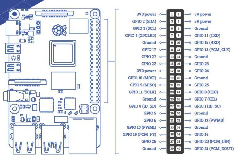
    Raspberry Pi GPIO pins

    You can use Raspberry Pi’s GPIO pins to pass electrical voltage to and from other components. Some of the pins have specific uses, such as power or ground connections, and others can be configured with software programs to send signals between Raspberry Pi and the rest of the circuit. Above is a breakdown of all the pins. Look carefully at physical pins 1 and 6: these will be the pins we use in our LED circuit later. Note that the pin numbers aren’t the same as the GPIO numbers; for example, GPIO 2 is actually physical pin 3.

    GPIO Pins on Raspberry Pi

    Prototype circuits with breadboards

    Breadboards come in several different sizes and are made of plastic with a matrix of holes. In each hole is a connector which joins it to other holes on the same row.

    Breadboards come in several sizes to enable prototyping of a wide variety of projects

    The larger breadboards have two long rows of holes at the top and bottom. Sometimes called ‘rails’, these are generally used for power and ground connections. They are connected together as indicated on the diagram above.

    The inner part of the breadboard has two sections of holes. Each section has rows of five holes which are connected as indicated on the diagram. The two halves of the breadboard are a mirror image of each other.

    The break along the centre of the breadboard, often known as the ‘gutter’, enables mounting of integrated circuits (chips) with the legs of the chip going either side of the break.

    Click here for a more detailed article on using a breadboard.

    A breadboard is used to connect electronics. All five holes in a row are connected; all the long blue and red lines on the end are all connected (and are used to for power)

    Basic prototyping components

    Here are the common prototyping components you will find:

    Jumper lead

    These connect your components to the Raspberry Pi. They can either have male or female end connectors (you need female for the GPIO pins) and it’s a good idea to have a mix of both.

    LED

    Light-emitting diodes come in various colours. They glow when electricity flows through them. Because they are a diode, the current will only flow in one direction, so make sure that it is connected the right way round: the longer leg is the positive one and should be connected to the power (or GPIO output) pin. Always use a resistor in series with LEDs, otherwise they are likely to draw more current than they can handle and burn out.

    LED

    Resistor

    Resistors are available in various formats, but this is the most common format for prototyping. The coloured rings around the resistor indicate how much resistance it provides. For more details about how to read resistor values, see The MagPi magazine issue 64.

    Use resistors to control the amount of electricity flow around your circuits

    Switch

    Switches make and break circuits. When connected in series in a circuit, a switch will allow or stop the flow of electricity. You can get switches that stay in the position in which they are set, or ones that you need to keep your finger on to keep the circuit connected.

    Speaker

    Speakers can be huge and very loud or they can be very small – small enough to fit on a breadboard. These small speakers are called piezoelectric and are great for making robotic noises, but not much good for hi-fi music applications.

    Speaker

    Capacitor

    Capacitors store and release electrical charge. They can be used to even out the electrical current or provide a greater flow for a short time. Be careful when using capacitors, as they can still hold charge after the circuit has been disconnected.

    Transistor

    Transistors are used in many types of circuits. They can be used either as an amplifier, which means that a small current goes in but a bigger current comes out, or as an electrical switch to change the amount of electricity flowing through circuit. A transistor has three legs or connectors: the emitter, the collector, and the base.
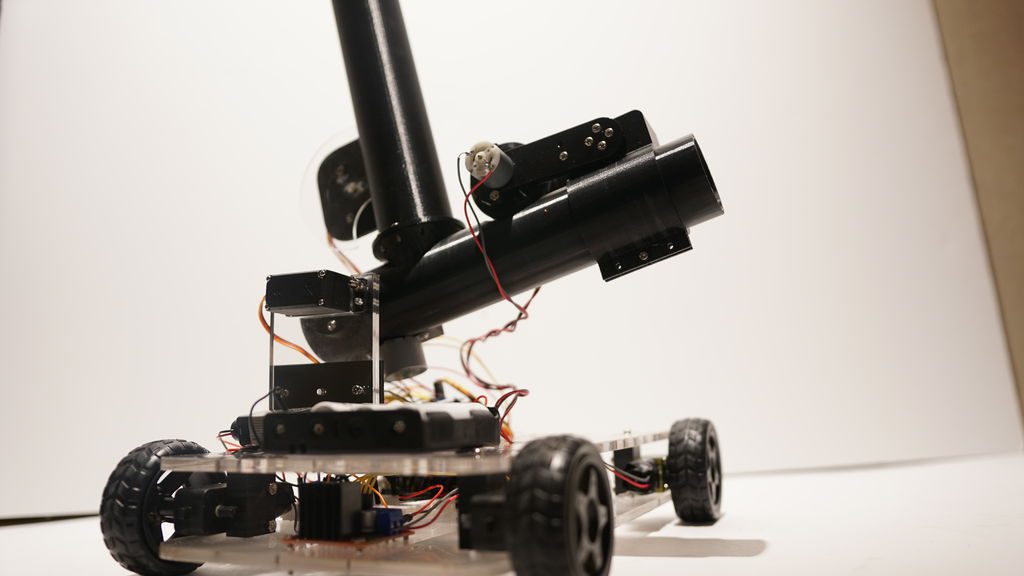
    Servo

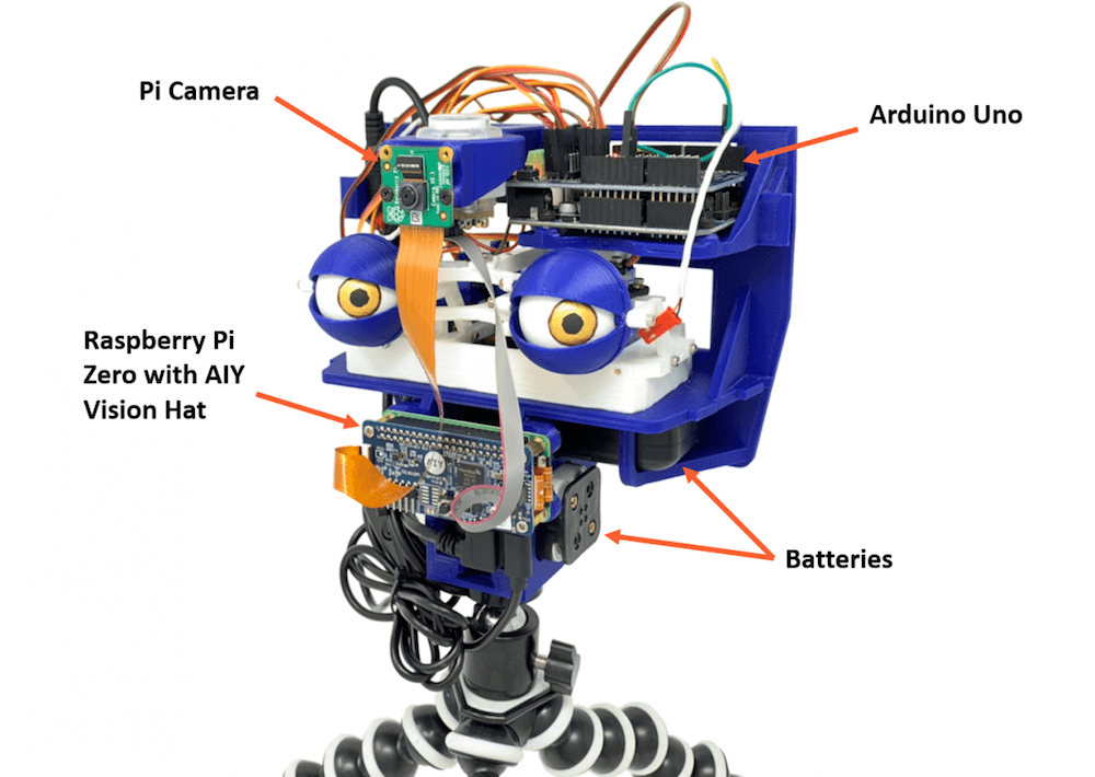
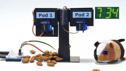
    Servos are used a lot in robotics for making things move. They can be connected directly to Raspberry Pi via the GPIO pins, but there are also extra plug-in boards (or HATs) that make it easier to connect many servos and control them more easily. Normally we use digital servos which use PWM (pulse-width modulation) signals to turn the armature on the servo from one position to another.

    Servo

    Battery

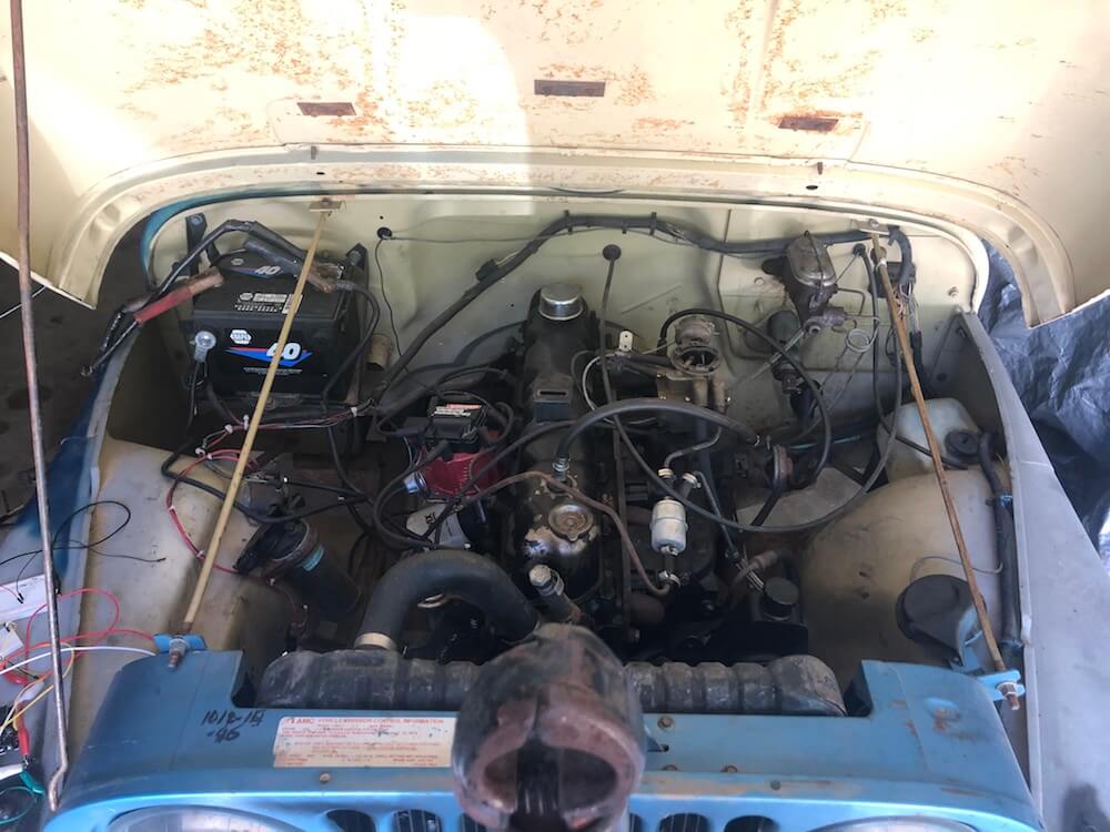
    Batteries can be all kinds of shapes and sizes, but for simple electronics projects you will normally be using 1.5 V AA or AAA type cylindrical batteries or 9 V square ones. Make sure you always have some spares or perhaps you may want to use rechargeable ones. Rechargeable batteries cost more, but can be used over and over. Make sure you connect batteries correctly and never directly connect the two contacts together, as even small voltage batteries can get very hot or even explode if ‘short-circuited’.

    Potentiometer

    Potentiometers are variable resistors and usually have a twisting knob or a slider to change the resistance. They have three connectors and can be used as game controllers or volume controls. Be careful if you are using a potentiometer instead of a resistor in your LED circuit: if you turn the resistance right down to zero, you may burn out your LED.

    Potentiometer

    Prototyping kits for Raspberry Pi electronics

    Instead of buying components separately, you will find it a lot easier to buy a kit packed with electronic components especially selected for Raspberry Pi.

    CamJam EduKits

    There are currently three CamJam EduKits available: a starter kit with all the components and more to make our LED circuit, a sensors kit to explore getting input from the world around you, and a robotics kit with wheels and motors to make your Raspberry Pi into a robot.

    CamJam EduKit

    Adafruit Parts Pal

    The Adafruit Parts Pal is a more comprehensive kit. It contains many popular components and prototyping parts, including LEDs, resistors, cables, sensors, and mechanical parts.

    Adafruit Parts Pal

    Elecrow CrowPi Educational Kit

    This is the daddy of all-in-one experimentation kits. There are chips and sensors, dials, speakers, numeric displays, and even a 7-inch HDMI touchscreen. It was developed with a Kickstarter appeal and is available directly from Elecrow in the US, or Amazon in the UK.

    Elecrow CrowPi

    Make an LED light circuit

    Building an electronic LED light circuit is a good way to start with electronics projects. To build this simple LED circuit you need the following:

    Everything can be found in the CamJam EduKit #1 (£5)

    Let’s dive into some practical circuit making with an example of how we can use the GPIO pins on the Raspberry Pi to make a circuit. We will go into the details of what the components are in a little while, but let’s look at what a circuit actually looks like on a diagram. We will use the power source of Raspberry Pi to light an LED (light-emitting diode). When electricity is passed through an LED, it glows. We will also need a resistor in our circuit to limit the amount of electricity that goes through the LED. If too much electricity flows, the LED may burn out.

    WARNING: When connecting components to the Raspberry Pi, it is always best to have the power off and unplugged in case you make a mistake with your wiring.

    The wires we use to connect components are called jumper leads. We connect components by mounting them on a breadboard. When the resistor and LED are placed in the circuit correctly, the LED will light up.

    Step 1: Turn off the power

    Make sure you have shut down your Raspberry Pi and unplugged its power cable. Plugging in jumper leads while switched on may be tolerated by Raspberry Pi, but in some cases it can cause a system crash or even damage to the hardware.

    Build the circuit

    Connect the components as shown in the wiring diagram below. Take careful note of the GPIO pins that you are connecting. The precise positioning of components on the breadboard is not so important, but make sure that the LED’s longer (positive) leg is connected to the 3V3 power pin via the jumper lead.

    Light it up

    When you are sure that you have connected everything correctly, plug in your Raspberry Pi. After a short time, the LED should light up as soon as the power GPIO pins are energised. If the LED does not light up, try connecting it the other way around, as it will only work one way.

    You’ll find two Raspberry Pi electronics projects in The MagPi magazine issue 91: Cheerlights and Reaction timer, by Dr. Simon Monk. Follow these tutorials to continue your Raspberry Pi electronics journey.

  • Creating an online robot fighting game using Arduino MKR1000 WiFi

    Creating an online robot fighting game using Arduino MKR1000 WiFi

    Reading Time: 7 minutes

    This is a guest post from Surrogate, a team of developers building games that people play in real-life over the internet.

    We introduced this concept last year, and have launched three games so far. Our final game of 2019 was SumoBots Battle Royale — where players from anywhere in the world can fight real robots in a battle royale-style arena. The aim of the project was to have the game run semi-autonomously, meaning that the bots could self-reset in between the games, and the arena could run by itself with no human interaction. This was our most complex project to date, and we wanted to share some parts of the build process in more detail, specifically, how we’ve built these robots and hooked them online for people to control remotely.

    Robot selection

    We’ve started our process by choosing which robots we’d want to use for the game. There were a couple of requirements for the robots when making the evaluation:

    • Are able to withstand 24/7 collision
    • Easily modifiable and fixable
    • Can rotate on the same spot
    • Must have enough space to fit the electronics

    After looking at a lot of different consumer robots, maker projects, and competitive fighting bots, we’ve decided to use the JSUMO BB1 robots for this game. We liked the fact that these bots have a metal casing which makes them very durable, all parts are easily replaceable and can be bought separately, and it has 4 independent motors (motor shields included), one for each wheel, which allows it to rotate on the same spot.

    We were pretty skeptical of being able to fit all the electronics into the original casing, but we decided to go with this robot anyways, as it had the best overall characteristics. As this robot is easily modifiable, we can always 3D print an extra casing to fit all the parts.

    What is the board?

    Now that we’ve decided on the robot, it was the time to define what electronics should we use in this build. As usual, it all starts with the requirements. Here’s what we need for the game to run smoothly:

    • The robot should be able to recover from any position
    • Can stay online while charging
    • Supports WiFi network connection and offers reliable connectivity
    • Easily programmable and supports OTA updates
    • Can control four motors simultaneously

    Based on these requirements we had the following electronics layout in mind:

    We had to find a board that is energy efficient, can send commands to motors, supports parallel charging and has a small footprint on the robot size. With so many requirements, finding the perfect board can be a challenge.

    Arduino to the rescue

    Fortunately, Arduino was there to help us out. They offer a rich selection of boards to fit every possible robotics project out there and have very detailed documentation for each of the boards. 

    More importantly, Arduino is known for its high quality, something that is crucial for semi-autonomous types of applications. Coming from an embedded software background and having to work with all sorts of hardware, we often see that some features or board functionalities are not fully finished which can lead to all sorts of unpleasant situations.

    After looking at the Arduino’s collection of boards we quickly found a perfect candidate for our project, the Arduino MKR1000 WiFi. This board fits all of our main requirements for the motor controls, is easily programmable via Arduino IDE, and due to its low power design is extremely power efficient, allowing us to have a lower capacity battery. Additionally, it has a separate WiFi chip onboard, which solely focuses on providing a reliable WiFi connection, something that is very important in our use case.

    Now that we’ve decided on the “brain” of our robot, it was time to choose the rest of the components.

    Robust hardware means working software

    Something to keep in mind is that when working with hardware, you should always try to avoid any possible risks. This means that you should always over-do your minimal hardware requirements where possible. The reason is — if your hardware doesn’t work as intended, your whole software stack becomes unusable too. Always chose reliable hardware components for mission-critical applications.

    Some of our electric components might look a bit overkill, but due to the nature of our projects, they are a critical requirement.

    Avoiding the battery explosions

    As there is a lot of robot collision involved in the game, we decided to go with a high safety standard battery solution. After evaluating multiple options on the market, we decided to go with the RRC2040 from RRC (Germany). It has a capacity of 2950 mAh that allows us to run the robots for up to five hours on a single charge. It has an internal circuitry for power management, protection features and it supports SMBUS communications (almost like I2C), and is certified for all of the consumer electronics battery standards. For charging, we used RRC’s charging solution designed specifically for this battery and that offers the possibility to feed power to the application while the battery is being charged.

    Note: the Arduino MKR1000 has a pretty neat charging solution on the board itself. You can connect the battery to the board directly as the main power source, and you charge it directly through the MKR1000’s micro USB port. We really wanted to use it to save space and have a more robust design, but due to the large capacity of our battery, we couldn’t use it at full potential. In our future projects with smaller scale robots, we definitely plan to use the board’s internal charging system, as it works perfectly for 700-1800 mAh power packs.

    Bot recovery

    For the bot to be able to recover from falling on its head, we’ve implemented a flipping servo. We didn’t want to have any risk of not enough torque, so we went with DS3218, which is capable of lifting up to 20KG of weight. Here’s how it works:

    Hooking everything together

    Now that we’ve decided on all of the crucial elements of this setup, it was time to connect all the elements together. As the first step, we figured what would be the best step way to locate all the pieces within the bot. We then 3D-printed a casing to protect the electronics. With all of the preliminary steps completed, we’ve wired all of the components together and mounted them inside of the casing. Here’s how it looks:

    It was really convenient for us that all the pins on the board could be connected just by plugging them in, this avoids a lot of time spent on soldering the cables for 12 robots and more importantly, allowed us to cut out the risk of bad soldering that usually can’t be easily identified.

    Arduino = Quick code

    Arduino MKR1000 offered us the connectivity we needed for the project. Each sumo robot hosts their own UDP server using MKR1000 WiFi libraries to receive their control commands for a central control PC and broadcasting their battery charge status. The user commands are translated to three different PWM signals using Arduino Servo library for the flipping, left and right side motor controllers. The board used has support for hardware PWM output which was useful for us.  Overall we managed to keep the whole Arduino code in a few hundred lines of code due to the availability of Servo and Wifi libraries.

    The out of the box ArduinoOTA support for updating the code over the WiFi came in handy during the development phase, but also anytime we update the firmware for multiple robots at the same time. No need to open the covers and attach a USB cable! We created a simple Bash script using the OTA update tool bundled in Arduino IDE to send firmware updates to every robot at the same time.  

    To summarize

    It’s pretty amazing that we live in the age where you can use a mass market, small form factor board like the Arduino MKR1000 and have so much functionality. We’ve had a great experience developing our SumoBots Battle Royale game using the board. It made the whole process very smooth and streamlined, the documentation was right on point, and we never had to hit a bottleneck where the hardware wouldn’t work as expected.

    More importantly, the boards have proven to be very robust throughout the time. These SumoBots have been used for more than 3,000 games already, and we haven’t seen a single failure from the MKR1000. For a game where you literally slam the robots in to each other at a high speed, that’s pretty impressive to say the least.

    We look forward to working with Arduino on our future games, and we can’t wait to see what they will be announcing in 2020!

    Website: LINK