Electronics 101.1: Electricity basics
In HackSpace issue 9, Dave Astels helps us get familiar with what electricity is, with some key terms and rules, and with a few basic components. Get your copy of HackSpace magazine in stores now, or download it as a free PDF here.

tl;dr There’s more to electricity than Pikachu.
Electricity basics
Electricity is fascinating. Most of our technology relies on it: computers, lights, appliances, and even cars, as more and more are hybrid or electric. It follows some well-defined rules, which is what makes it so very useful.
According to Wikipedia, electricity is ‘the set of physical phenomena associated with the presence and motion of electric charge’. And what’s electric charge? That’s the shortage or excess of electrons.
Let’s go back (or forward, depending on where you are in life) to high school science and the atom. An atom is, at a very simplified level, a nucleus surrounded by a number of electrons. The nucleus is (again, viewing it simply) made up of neutrons and protons. Neutrons have no charge, but protons have a positive charge. Electrons have a negative charge. The negative charge on a single electron is the exact opposite of the positive charge on a single proton. The simplest atom, hydrogen, is made from a single proton and a single electron. The net charge of the atom is zero: the positive charge of the proton and the negative charge of the electron cancel – or balance – each other. An atom’s electrons aren’t just in an amorphous cloud around the nucleus: you can think of them as being arranged in layers around the nucleus…rather like an onion. Or perhaps an ogre. This is a very simplified visualisation of it, but it suffices for our purposes.
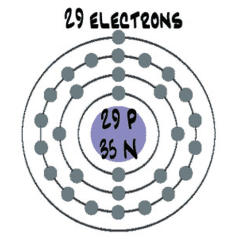
Figure 1: A very stylised representation of a copper atom with its electron shell
In a more complex atom, say copper, there are more protons, neutrons, and electrons, and the electrons are in more layers. By default, a copper atom has 29 protons and 35 neutrons in its nucleus, which is surrounded by 29 electrons. The way the electrons are distributed in their layers leaves the copper atom with a single electron in the outermost layer. This is represented in Figure 1 (above). Without getting further into subatomic physics, let’s just say that having that single electron in the outermost layer makes it easier to manipulate. When we put a bunch of copper atoms together to make copper metal (e.g. a wire), it’s easy to move those outermost electrons around inside the metal. Those electrons moving around is electricity. The amount of electrons moving over a period of time is called ‘current’.
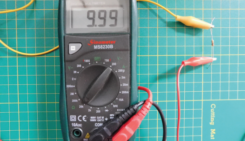
A single 10 kΩ resistor reads almost 10 000 ohms (no electrical component is perfect).
We started by talking about electrons and charge. Look back at the Wikipedia definition: ‘presence and motion of electric charge’. Charge is measured in coulombs: 1 coulomb is approximately 6.242 × 10¹⁸ electrons. That’s 6 242 000 000 000 000 000 electrons. They’re very small. Actually, this would be -1 coulomb. +1 coulomb would be that many protons (or really, the net lack of that many electrons).
That’s charge. Now let’s consider moving charge, which is far more useful in general (unless your goal is to stick balloons to the wall). Consider some amount of charge moving through a wire. The amount of charge that moves past a specific point (and thus through the wire) over a period of time is called ‘current’ (just like the current in a river) and is measured in amperes, generally just called amps. Specifically, 1 amp is equal to 1 coulomb flowing past a point in 1 second.
Another common term is voltage. You can think of voltage like water pressure; it’s the pressure pushing the electrons (i.e. charge) through a material. The higher the voltage (measured in volts), the faster charge is pushed through, i.e. the higher the current.
The final term is resistance, measured in ohms. Resistance is just what it sounds like. It’s a measure of how much a material resists the movement of electrons. We said that copper allows electrons to move freely. That’s what makes it so common for wires, PCB traces, etc. We say that it is a good conductor. Glass, on the other hand, locks its electrons in place, not letting them move. It’s an example of a good insulator. There are materials that are in between: they let electrons move, but not too freely. These are crucial to making electronics work.
There’s an interesting (and useful) relationship between voltage, current, and resistance called Ohm’s Law (Georg Ohm was the fellow who explored and documented this relationship): the current (denoted I, in amps) flowing through a material is equal to the voltage across the material (denoted V, in volts) divided by the material’s resistance (denoted R, in ohms): I = V/R. This equation is foundational and, as such, very handy.
Lighting up
There aren’t many electronic devices that don’t have at least one LED on them somewhere, especially not gadgety ones. If you look at a simple Arduino Uno, it has LEDs for power, Tx, Rx, and pin 13. The first program using electronic components that most people try is one to blink an LED.

Figure 2: The colour spectrum
LED stands for light-emitting diode. We’ll come back to diodes in a later instalment; all we need to know right now is that a diode has to go the right way around. So that leaves ‘light-emitting’. That simply means that it gives off light: it lights up. Specifically, it lights up when enough current flows through it. Be careful, though. Put too much current through it and it’ll likely crack in two. Seriously, we’ve done it. Best case scenario, you’ll get a bright pulse of light as it burns out. How much current do they like? 20 milliamps (20mA) is typical. Because an LED is a diode, i.e. a semiconductor (we’ll look at these in more detail in a future instalment too), it defies Ohm’s Law. How? It always has the same voltage across it, regardless of the current flowing through it.
An LED will have a specific Vf (f is for forward, as in ‘forward voltage’), which will be defined in its data sheet.
The voltage varies with the colour of light that the LED emits, but usually between 1.8V and 3.3V. Vf for red LEDs will typically be 1.8V, and for blue LEDs 3V–3.3V. As a rule, LEDs with a higher frequency colour will have a larger Vf. Figure 2 (above) shows the colour spectrum. Colours on the right end are lower in frequency and LEDs emitting those colours will have a lower Vf, while those on the left end have a higher frequency and a higher Vf.
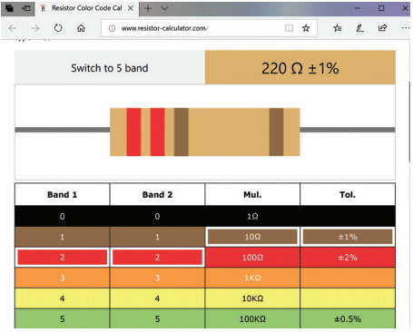
Resistor colour bands show the resistance. Online calculators can help you learn the values.
So an LED will have a fixed Vf, and a typical LED that we’ll use likes about 20mA of current. An LED won’t do anything to limit how much current is flowing through it. That’s what we meant when we said it defies Ohm’s Law.
If we take a blue LED and hooked it to a 3.3V power supply, it will shine happily. Do the same thing with a red LED, and it will blink and burn out. So how do we deal with that? How do we use 3.3V or 5V to make an LED light up without burning out? We simply limit the current flowing through it. And for that, we need a resistor and Ohm’s Law.
Getting protection
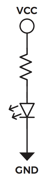
Figure 3: An LED with a current-limiting resistor
If we want to power a red LED from a 5V source, we know the following information: current has to be 20mA, Vcc will be 5V, and the voltage across the LED will be 1.8V. Consider the circuit in Figure 3. The voltage across the resistor will be Vcc – Vf, i.e. 5 – 1.8 = 3.2V. We said the current through the LED should be 20mA. Since there is only one path through the circuit that goes through the resistor as well as the LED, all current has to flow through both: whatever amount of current flows through the resistor has to flow through the LED, no more, no less. This is the crucial thing to realise. We can calculate the value of the resistance needed using Ohm’s Law: R = V/I = 3.2V/20mA = 3.2V/0.020A = 160 ohms.
The resistor should have a value of 160 ohms to allow 20mA of current to flow through the LED. Knowing that the 20mA and 1.8V values are approximate and that resistors are not exact (+/- 5 or 10 percent are the most common), we chose a slightly higher-value resistor. Considering common resistor values, go with 180 ohm or 220ohm. A higher-value resistor will allow slightly less current through, which might result in a slightly dimmer light. Try it and see. For practical purposes, simply using a 220 ohm resistor usually works fine.
Parallel lines
In the previous section we connected a resistor and an LED end to end. That’s called a series circuit. If we connected them side by side, it would be a parallel circuit. Consider the circuits in Figure 4.

Figure 4: A – series circuit; B – parallel circuit
We’ll use 5V for Vcc. What is the total resistance between Vcc and GND in each circuit? How much current is flowing through each circuit? What is the voltage across each resistor?
When resistors are connected in series, as in circuit A, the resistances are added. So the two 100 ohm resistors in series have a total resistance of 200 ohms.
When resistors are connected in parallel, as in circuit B, it’s more complex. Each resistor provides a path for current to flow through. So we could use an indirect method to calculate the total resistance. Each resistor is 100 ohms, and has one end connected to 5V and the other to 0V (GND), so the voltage across each one is 5V. The current flowing through each one is 5V/100 ohms = 0.05A, or 50mA. That flows through each resistor, so the total current is 100mA, or 0.1A. The total resistance is then R = V/I = 5V/0.1A = 50 ohms. A more direct way is to use the equation 1/Rt = 1/R1 + 1/R2 + … + 1/Rn, where Rt is the total resistance, and R1, R2, etc. are the values of the individual resistors that are in parallel. Using this, 1/Rt = 1/100 + 1/100 = 2/100 = 1/50. So Rt = 50. This is a quicker way to do it, and only involves the resistor values.
A multimeter can read voltage, ampage, and resistance
Now for current. We know that the series circuit has a total resistance of 200 ohms, so the current will be I = V/R = 5V/200 ohm = 0.025A = 25mA. For one 100 ohm resistor the current is 5V/100 ohm = 0.05A = 50mA. This is expected: if the resistance is lower, there is less ‘resistance’ to current flowing, so with the same voltage, more current will flow. We already computed the current for the parallel circuit: 100mA. This is higher because we know that each resistor has 50mA flowing through it. In a parallel circuit, the currents are added.
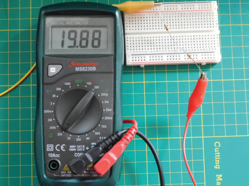
Two 10kΩ (kiloohm) resistors in series read (almost) 20kΩ
The final question is what voltage is across each resistor. Let’s look at the parallel circuit first. One end of each resistor is connected to 5V, and the other end of each is connected to 0V (GND). So clearly, the voltage across each one is 5V. In a series circuit it’s different. We can use Ohm’s Law because we’ve calculated the current flowing through each one (0.025A), and that current flows through both resistors. Each resistor is 100 ohm, so the voltage across each one will be V = I×R = 0.025A × 100 ohm = 2.5 V. This makes sense intuitively, since the resistors have the same value and the same current is flowing through both. It makes sense that the voltage across each would be equal, and half of the total. Remember that it’s unlikely to be exactly half, due to the slop in the resistor values.
Let’s do this one more time with unequal resistors. See Figure 5.

Figure 5: A – series circuit; B – parallel circuit
For the series circuit, we simply add the resistances: 100ohm + 82ohm = 182ohm. The current is 5V / 182ohm = 0.0274725A = 27.4725 mA. Because resistors are inexact, it’s safe to call this 27.5mA. The voltages are 100ohm × 0.0275A = 2.75V across the 100 ohm resistor, and 82ohm × 0.275 = 2.25V across the 82 ohm one. The voltages always have to add up, accepting rounding errors. Relative to ground, the voltage at the point between the resistors is 2.75V. What will happen if we make the top resistor smaller (i.e. have a lower resistance)? The total resistance goes down, the current goes up, so the voltage across the 100ohm resistor goes up. This is what’s generally called a voltage divider.
For the parallel circuit we can use 1/Rt = 1/100 + 1/82 = 82/8200 + 100/8200 = 182/8200 = 1/45, so Rt = 45ohm. The total current is 5V / 45ohm = 0.111A = 111mA. For the individual resistors, the currents are 5V / 100ohm = 50mA and 5V / 82ohm = 61mA. Add these up and we have the total current of 111mA. Parallel resistors act as a current divider.
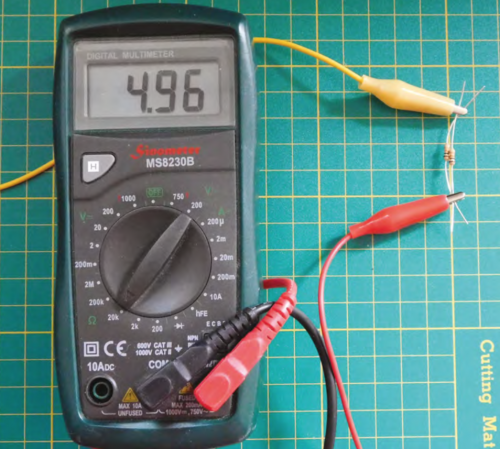
Two 10kΩ resistors in parallel read (almost) 5kΩ.
I encourage you to create these little circuits on a breadboard and measure the resistances, voltages, and currents for yourself.
Resistors in series for a voltage divider, resisters in parallel for a current divider
Consider what happens if we replace the resistor connected to Vcc in a series circuit with a variable resistor. The voltage between the resistors will vary as the value of the resistor does. As the resistance goes down, the voltage goes up. The reverse is true as well: as the resistance goes up, the voltage goes down. One use of this is to replace the variable resistor with a photoresistor. A photoresistor’s value depends on how much light is shining on it (i.e. how many photons are hitting it, to be precise). More light = lower resistance. Now the voltage divider can be used to measure the strength of light. All you need to do is connect the point between the resistors to an analogue input and read it.
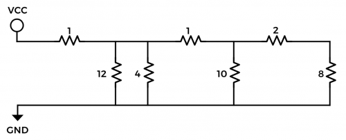
Figure 6 Combined parallel and series circuits
We’ve had a brief look at the basic concepts of electricity: charge, current, voltage, and resistance. We’ve also had a closer look at resistors and ways of combining them. We finished with a practical example of a series resistor circuit being used to measure light.
Website: LINK