
This DIY tool automates LED testing and current limit calculations
GPIO pins on most microcontrollers operate at low voltages, typically between 3.3V and 5V, and are unable to deliver much current — oftentimes stopping at 20-40mA. This is why, when setting up an LED, series resistors are used to limit the amount of current draw and prevent damage to the pin. Mirko Pavleski created a workbench device that helps figure out the size of this resistor and allows for an LED to be connected for live testing.
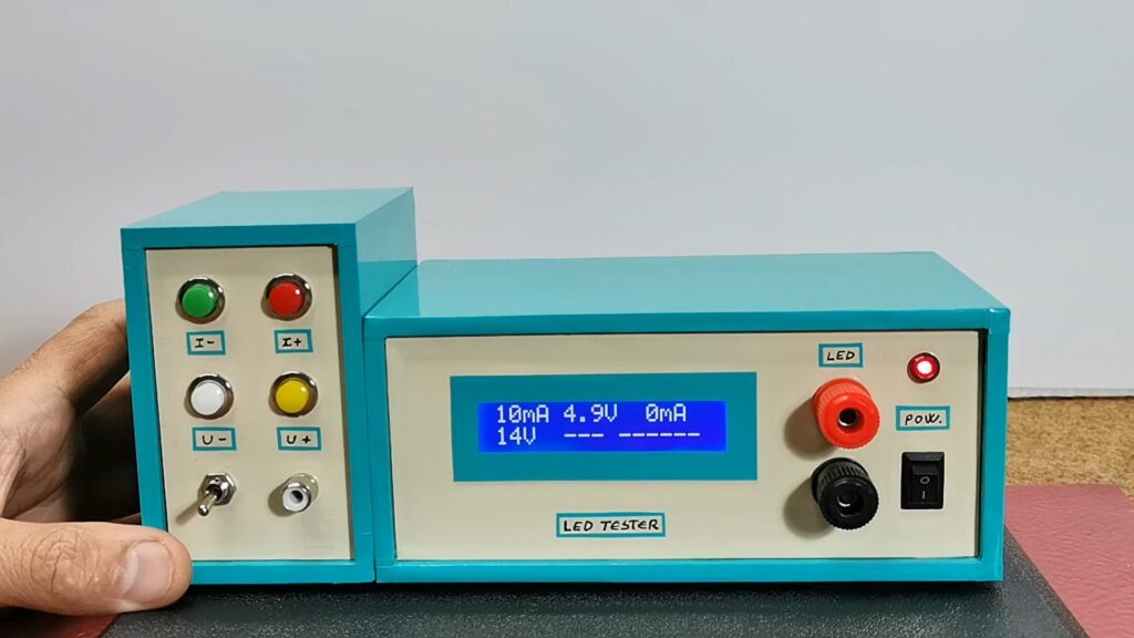
Built around an Arduino Nano, the system presents the user with a display for selecting the desired maximum current draw and LED voltage input. The panel of buttons on the left can increment or decrement the ideal voltage/current levels that, in turn, are then used to calculate the value of the series resistor. This value appears on the bottom alongside the part number for ordering the resistor from a distributor.
The values at the top of the LCD indicate how the connected LED currently behaves given a known voltage. By wiring the LED to a couple of sense resistors and an analog input pin, its forward voltage along with its current draw can be determined.
More details about this project can be found in Pavleski’s Hackaday.io write-up here.
The post This DIY tool automates LED testing and current limit calculations appeared first on Arduino Blog.
Website: LINK