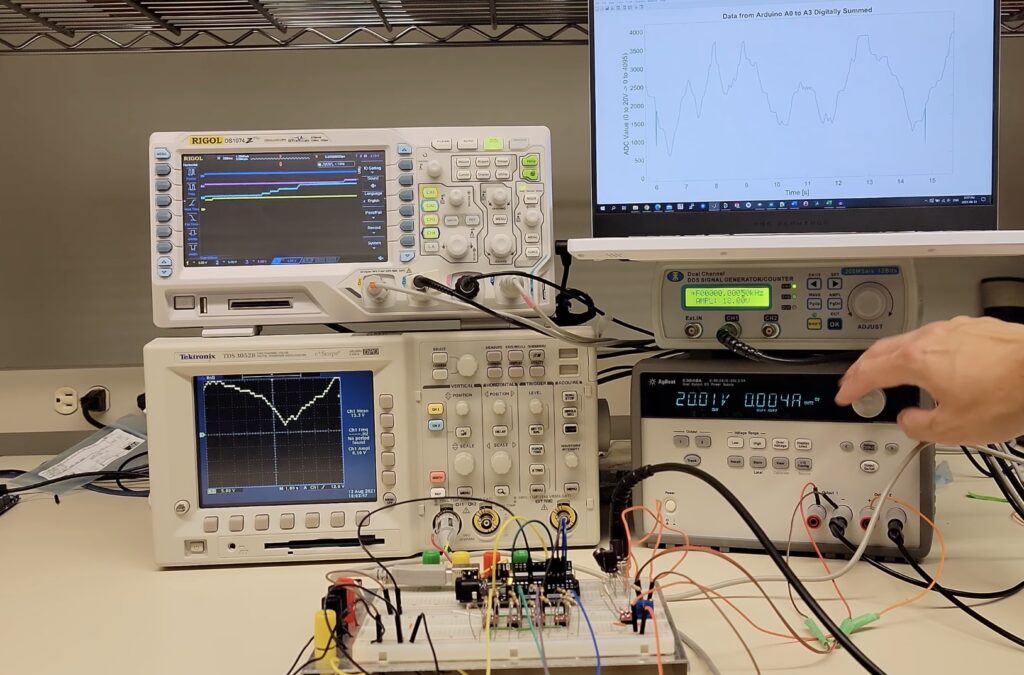
The Arduino Uno is well-known for its 10-bit 5V ADC within its ATmega328p, which means that it takes between 0 and 5V as input and produces a digital value that ranges from 0 to 1023. However, attempting to measure any voltage above 5V will cause some less-than-desirable results, such as creating magic smoke and destroying the IC. To get around this problem, some makers add a voltage divider that divides the incoming voltage by a predetermined factor. This solution reduces the resolution of the ADC, as a single unit of change in the digital value corresponds to a larger change in voltage. To address this, the YouTuber known as Techoyaki came up with a novel solution that can measure the full range of values without decreasing the resolution.
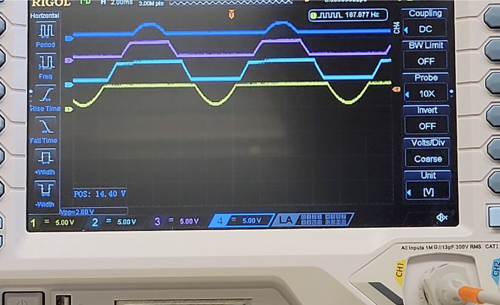
His project employs a series of four limiting rail-to-rail MOSFETs within a “quantizer” circuit to slice the incoming 20V current into discrete “chunks” that each range from zero to five volts. Just before the MOSFETs are four differential op-amps that essentially split the waveform into four layers. After the Arduino has read the values from the four analog input pins, it sums the values to produce the equivalent of a 12-bit ADC, thus leading to values that fall between 0 and 4095.
For more information about the circuitry and how this project was built, you can view Techoyaki’s video below!
Knowing the exact depths that water reaches within a harbor can be vital to navigating around certain hidden obstacles that might cause a boat to become stuck. But rather than using an expensive drone or even satellite to take these measurements, Jan Neumann was able to create a DIY version that is a fraction of the cost.
The system is comprised of an Arduino Uno at its core with a small GPS module for gathering positional data and a NMEA-capable echo sounder. As Neumann’s boat moved around the harbor, the Uno would take a reading of the water’s depth and the boat’s current position every second and log it to an SD card within a CSV file. And because the water’s natural level rises and falls over the course of a few hours due to tidal forces, Neumann used a Wasser&Schiffahrsamt water level sensing module that also takes a reading every second.
With all the data now in a large series of tables, it was passed to a Python script that filled in any missing datapoints and adjusted the water level based on the calibrated value. Finally, a second Python script placed each datapoint into a graph and interpolated between the points to create a smooth map. As seen in the subsequent image, the whole setup was quite effective at showing where the water was shallower or deeper.
You can read more about this project and see its code here on GitHub.
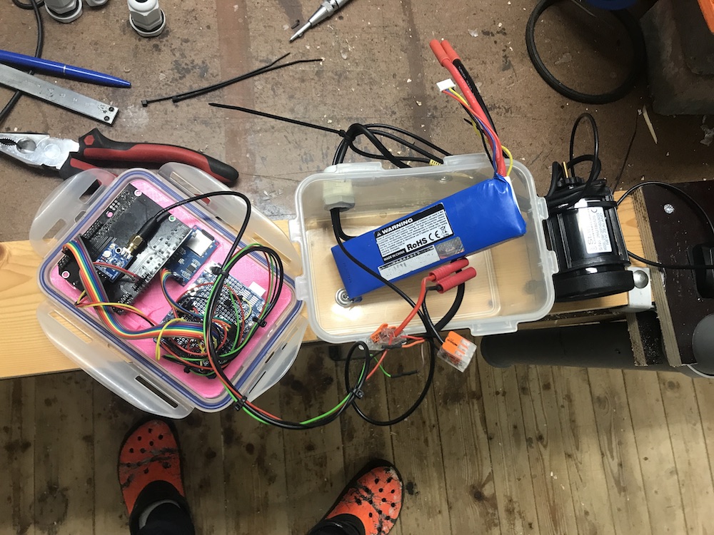
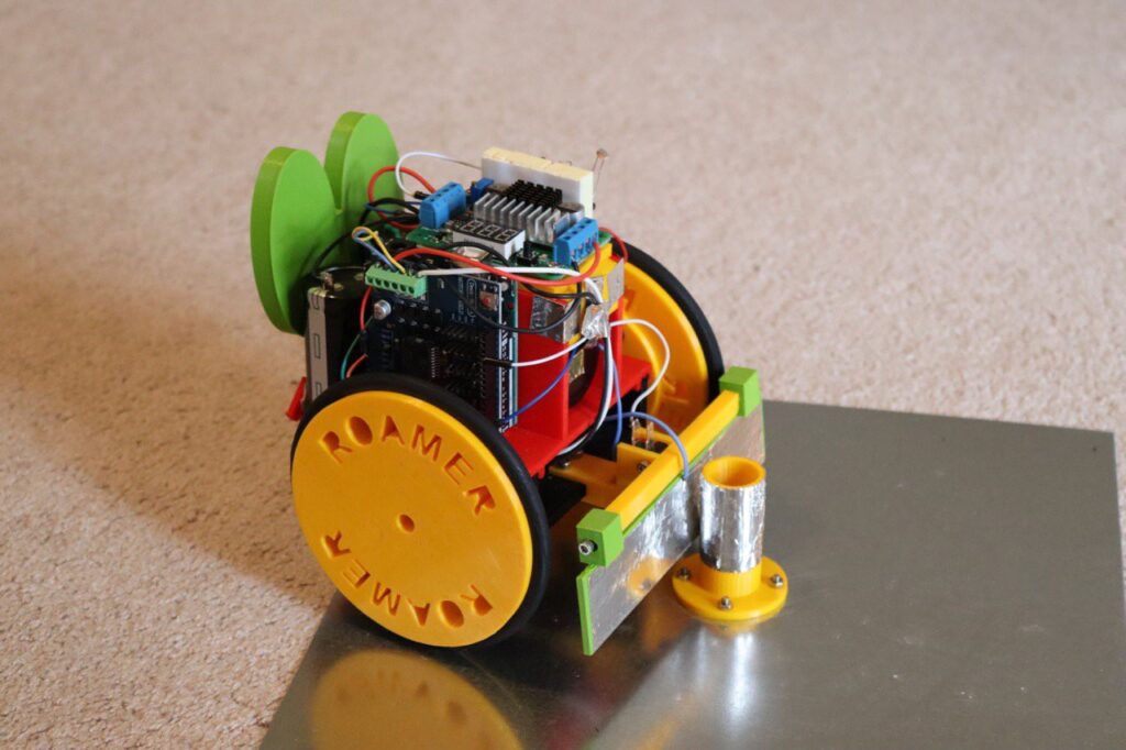
Tiny mobile robots are a blast to use. They are fast, fun, and can even be autonomous. However, they all suffer from a similar issue: batteries, which are notorious for running out of charge quickly when the motors are kept spinning for too long. To address this issue, Mike Rigsby came up with a small robot that has a simple “brain” but has the ability to never run out of power.
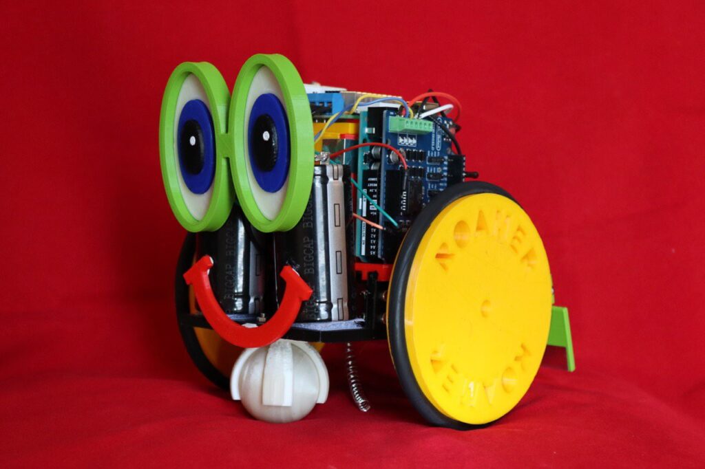
Rigsby’s robot, named Roamer, starts off on a charging station that is comprised of a large metal plate on the bottom and a small, energized bump rail. The bot contains a spring under its base that contacts the plate, and its front plate contacts the bumper. Therefore, when the two meet, the circuit is completed, and Roamer can determine if it needs to charge.
Roamer’s onboard Arduino Uno is paired with a motor shield that drives both continuous servo motors to both give forward/backward motion and turn side-to-side. There is also a photoresistor on the top of the robot that is used to sense if the room is dark or light. If it is bright enough, the rover will begin its normal pattern of moving in random directions until it needs to top off its batteries, but a dark room causes it to “sleep” until the light returns.
Roamer is a clever demonstration of how simple materials can be implemented to create a robot that can theoretically never run out of power. You can view this timelapse of it below as well as see how the rover was created here on Hackaday.io.
Use an Arduino touchscreen to draw the waveforms that you’d like your synth to produce
Arduino Team — August 16th, 2021
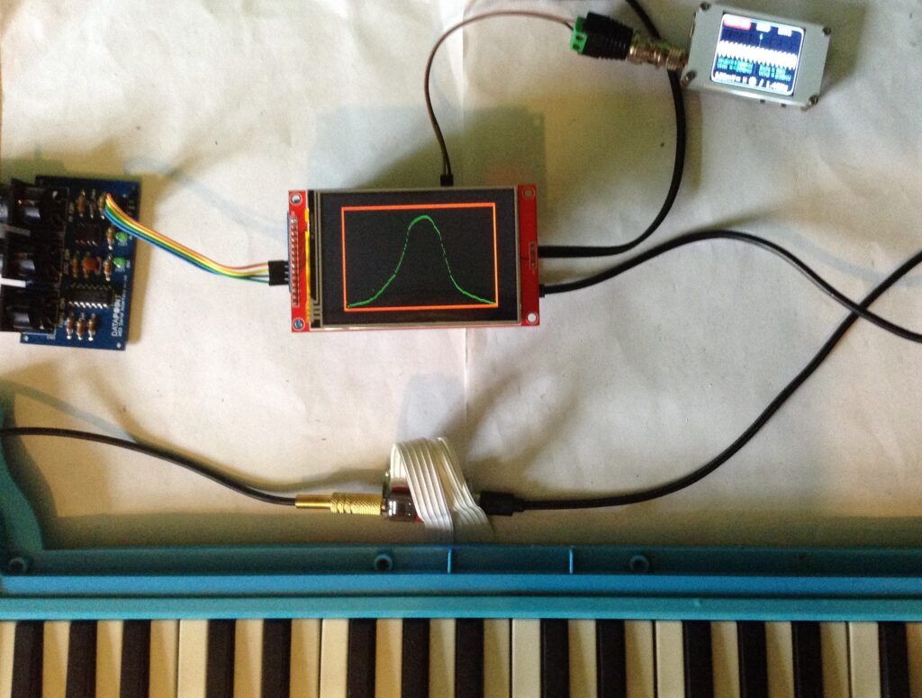
Ordinarily, producing complex waveforms on microcontrollers requires precise adjustments within code in order to work, and this can become quite tedious. Additionally, having to wire up physical inputs such as potentiometers for quick tuning adds a lot of sprawl to a project. This is partially what inspired Kevin, who runs the DIY Electromusic website, to construct a small, Arduino-based device that allows users to sketch the waveform they want outputted via PWM.
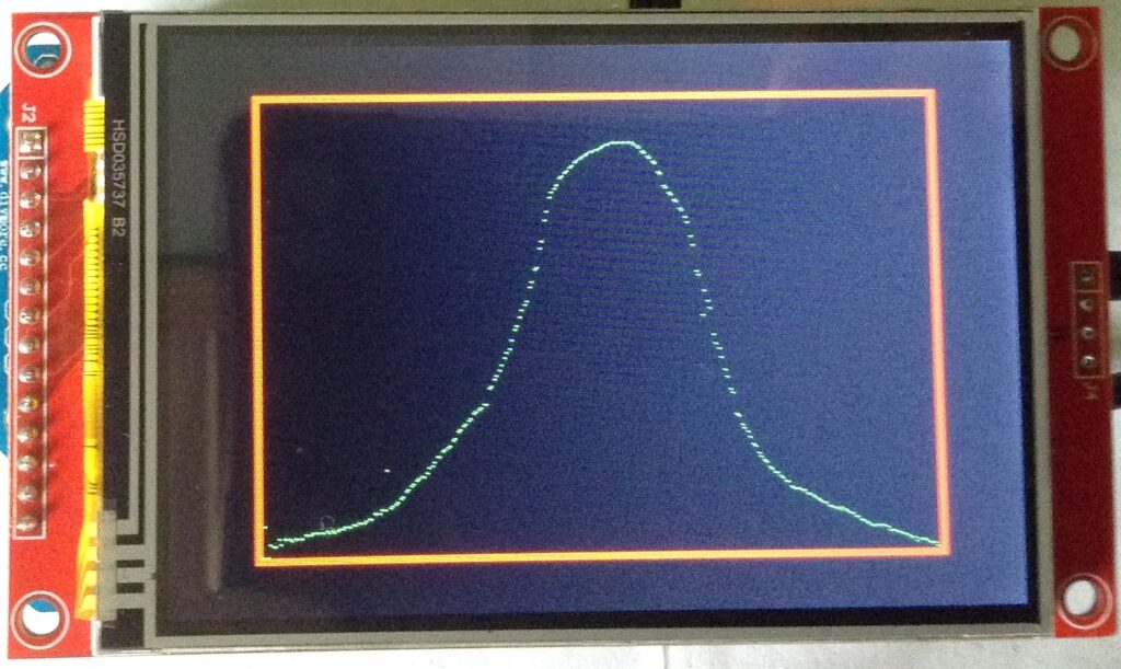
The main components of this project are the ILI9488 TFT shield that fits onto an Arduino Uno, along with an amplifier/speaker and an optional output filtering circuit to clean up the audio. Kevin’s unit takes in a MIDI note on the Uno’s RX pin and passes it through a wavetable function that applies the currently displayed waveform on the screen to the note being requested.
Kevin also made a slight modification to the previously mentioned project by replacing the wavetable with a series of five sliders that correspond to various parameters for a MIDI granular synthesizer. His analog version had five large potentiometers that plugged into the analog input pins on an Uno, but this newer version greatly cleaned things up and gives more room for experimentation.
To read more about these innovative audio control projects, you can view them on Kevin’s website here and see a quick demo below.
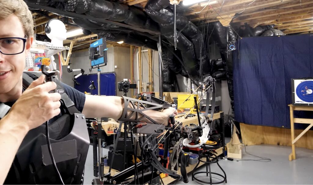
After becoming frustrated at his lack of archery skills and not wanting to spend an eternity practicing getting better, Shane Wighton (known as Stuff Made Here on YouTube) sought to build a rig that could automatically correct his aim for the perfect shot every time. The device is comprised of a rigid sleeve that fits over the wearer’s forearm, along with a pair of stepper motors that can adjust where the bow is pointing either vertically or horizontally via a rack-and-pinion. These motors are driven by an Adafruit microcontroller running CircuitPython and a couple of motor driver modules that provide the necessary current. But that’s not all, he also created a small rig that uses an Arduino Uno and servo motor to autonomously fling targets into the air.
Target tracking is achieved by having a set of eight OptiTrack cameras around the room monitor the space for tiny gray spheres, and through the use of a special triangulation algorithm, they can accurately determine where both the arrow is pointing and where the target is in 3D space. Initially, the system missed all of its shots due to poor software and the wrong kind of bow, so Wighton completely rewrote his program and switched to a compound bow instead.
Once everything had been corrected, the software was able to predict where a flying target would end up according to its speed, and thus had the ability to intercept it. The Auto-Aiming Bow could also hit a target the size of a 3mm-wide circle with scary precision.
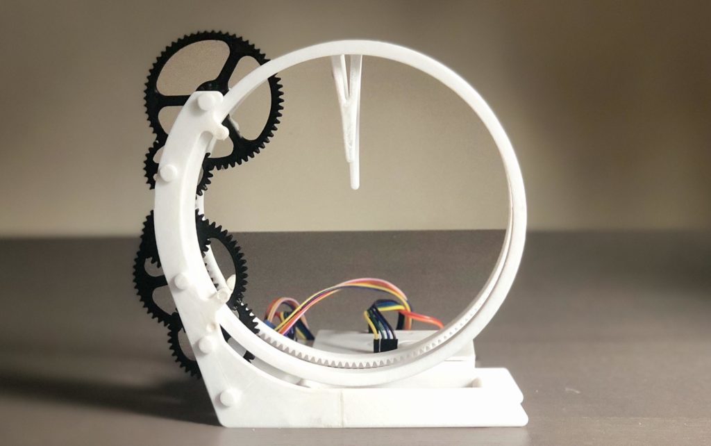
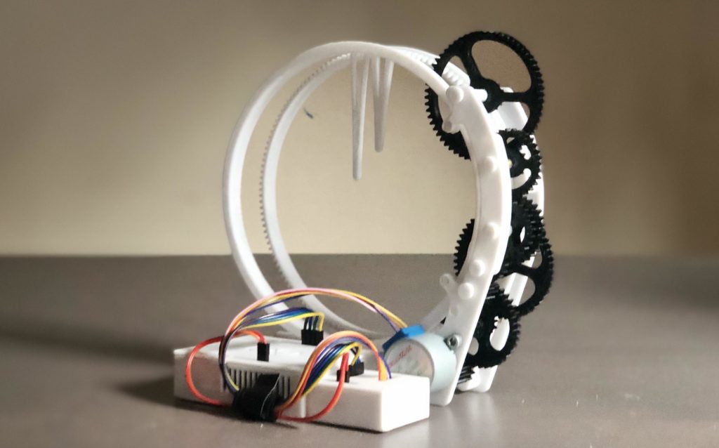
Simply looking at a traditional analog clock sitting on a wall somewhere got pretty boring for one Instructables user who goes by saulemmetquinn, which is partially why they wanted to create a novel design instead. Their device uses almost entirely 3D-printed components that come together to form the “Holo Clock,” since it seems holographic with its floating minute and hour hands.
The Holo Clock project started with a surprisingly complex design in CAD software. There are two rings that are lined with teeth that sit stacked horizontally. The back ring is the minute hand, and because it is moved almost directly by the stepper motor, it spins more quickly. The hour hand is driven by a set of gears that reduce the output of the minute hand’s cogs by a factor of 60, thus making it turn at the correct rate.
The electronics for the clock are extremely simple. It uses an Arduino Uno with a set of four output wires, along with power and ground, to control a ULN2003 stepper motor driver. This in turn outputs current to a generic 5V stepper motor that spins the first drive gear at a known, precise rate for consistent timing. Likewise, the code is also straightforward, as all it must do is step the motor a certain amount depending on how many steps are left within the loop.
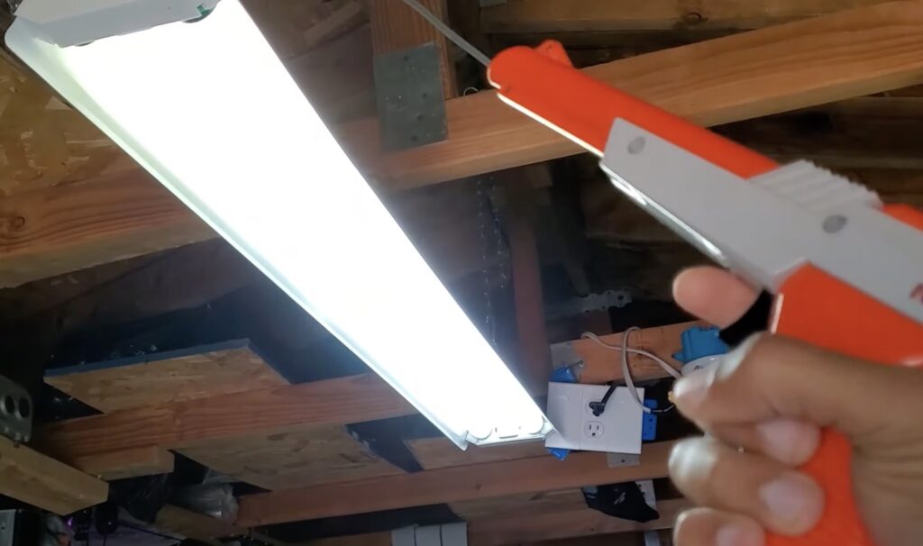
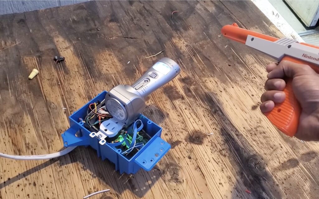
Those of us who have experienced the Nintendo Zapper while playing games such as Duck Hunt will probably have fond memories of it. However, with the rapid disappearance of CRT TVs and the aging of the physical mechanisms, YouTuber DuctTape Mechanic wanted to give an old Zapper a new lease on life. His modification integrated a small RF transmitting module into the top of the device, allowing it to be switched on by the trigger’s microswitch. With everything in place inside the Zapper, he moved onto the receiver.
In order to get the incoming signals from the RF transmitter and turn them into an action, a receiver circuit was necessary. First, he soldered an RF module to a breadboard, along with an opto-coupling IC that isolates the sensitive electronics. From here, the receiver connects to an Arduino Uno that sets a pin high or low to turn the relay module + opto-coupler circuit on or off. In its current configuration, the Zapper acts like a toggle switch, where one press toggles everything to on while a subsequent press toggles everything off.
As seen in the video below, being able to ‘zap’ your lights with the Nintendo Zapper looks really cool, and it will be interesting to see where DuctTape Mechanic takes it from here.
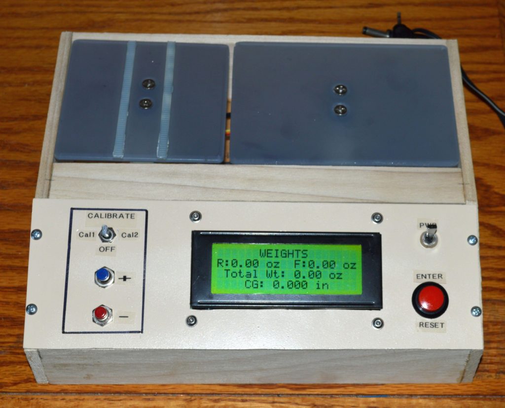
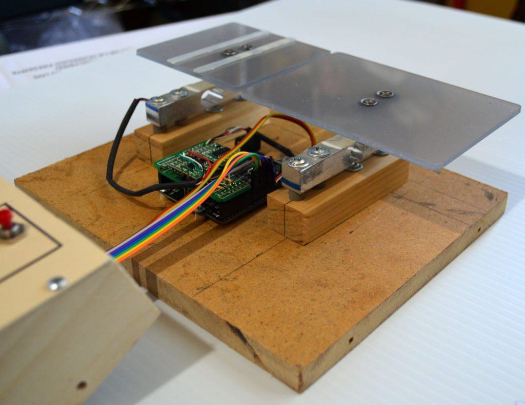
Constructing and racing a pinewood derby car is a great way to introduce young children to the world of engineering and mathematics. Many competitions will limit how heavy a car can be to avoid unfair advantages when it comes to momentum, meaning that contestants will try to add as much weight as possible. However, the center of gravity is also important since having it too far forward or backward can affect the acceleration or traction of the car. To address this problem, willemvl on Instructables created a small DIY scale that measures exactly where this center lands on the car to assist in balancing.
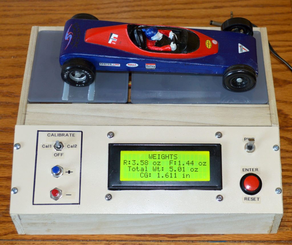
The main portion of the scale is the set of two load cells that measure the force being applied to their tops. They are connected to the Arduino Uno underneath via two digital IO pins. Data such as the front, rear, and total weight are displayed on a large 20×4 I2C LCD screen in the middle which is flanked by a set of buttons to calibrate the scale and begin measurements.
After going through the calibration process with a series of known weights and setting their calibration factors, the scale was ready to use. As can be seen in the project’s write-up, the center of gravity calculation is amazingly accurate, and it was used to help willemvl when he went to readjust the weights on the pinewood derby car.
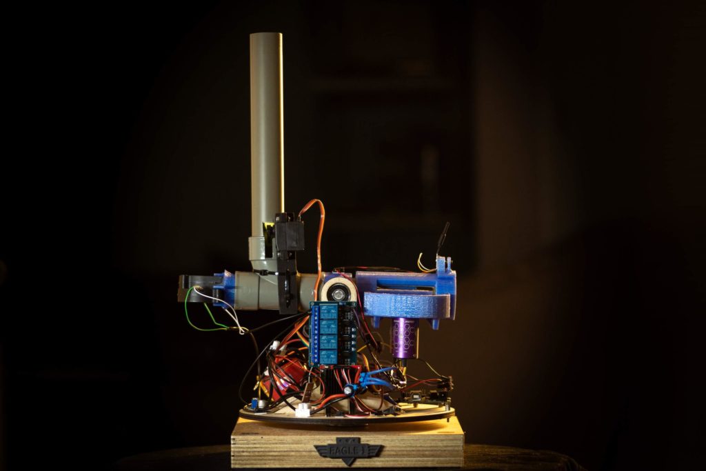
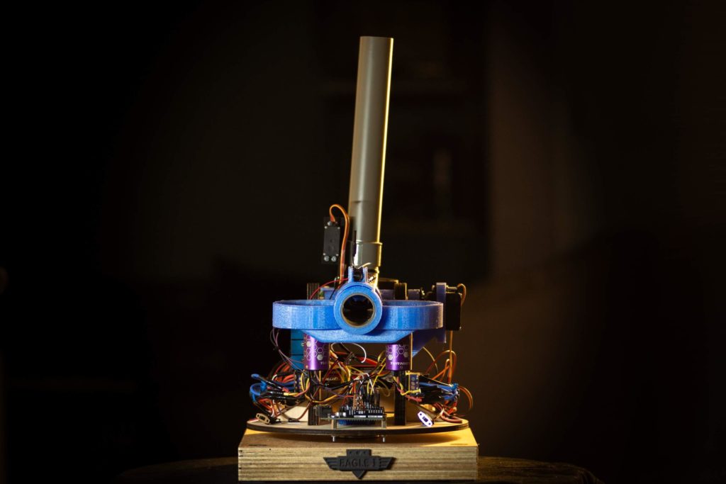
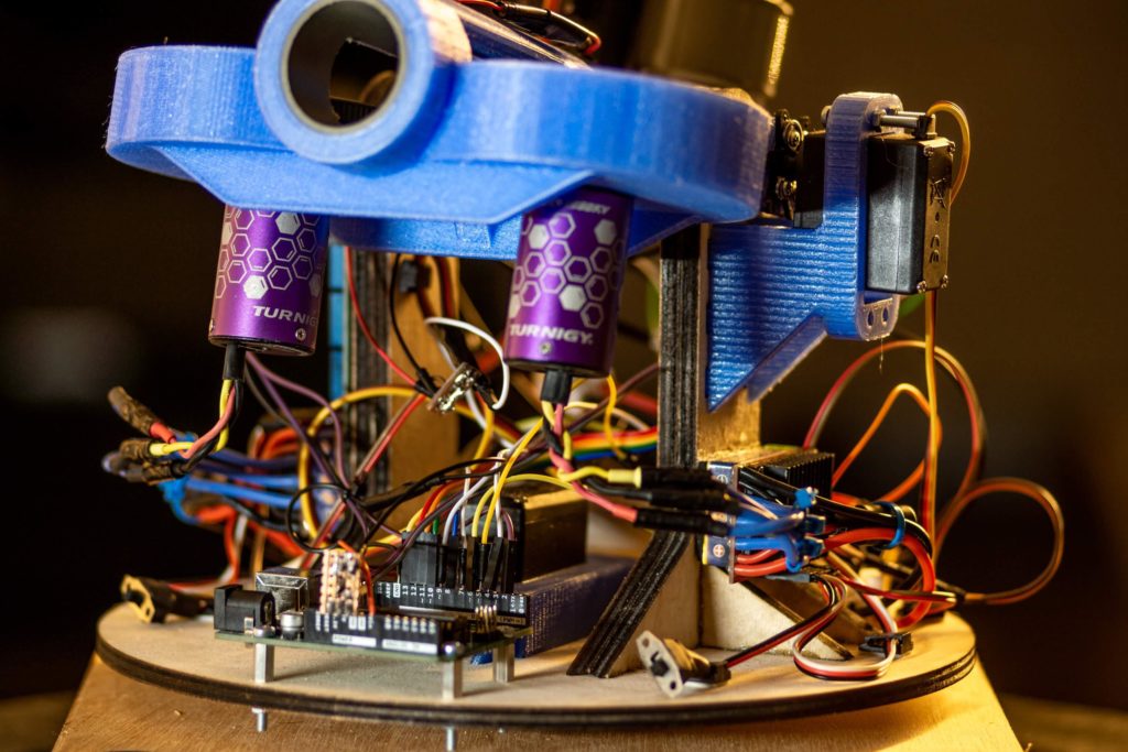
Named the grand prize winner of Instructables’ Arduino Contest, a maker known as otjones99 has created an interesting take on the classic Nerf sentry turret design by building one that uses an FPV headset to see and fire at targets. The turret consists of a turntable for moving the assembly side-to-side, along with a simple servo mechanism for tilting the end up and down. Small foam balls are ejected from the turret by a pair of counter-rotating wheels that were taken from a couple of blower style fans.
In order to control the rotating base and the loading/tilting mechanisms, a single Arduino Uno was positioned at the bottom and connected to the two servos and the ESCs for the spinning wheels. Commands for actuating the sentry are received by the onboard nRF24L01 wireless module that sends them to the Uno over the SPI bus.
The user is able to move the sentry turret by turning a pair of potentiometers within a Logitech joystick attached to an Arduino Nano. There is also a set of momentary pushbuttons to switch the safety on or off and to launch. This data gets transmitted from the nRF24L01 module onboard to the other one on the turret.
This project is a really fun way to explore both first-person control and topics in wireless communication. To read more about the sentry turret, you can check out otjones99’s well-documented tutorial here.
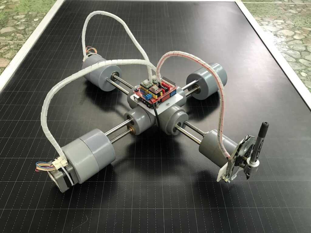
The P-CNC Plotter is a DIY drawing machine ‘disguised as a quadruped robot’
Arduino Team — July 27th, 2021
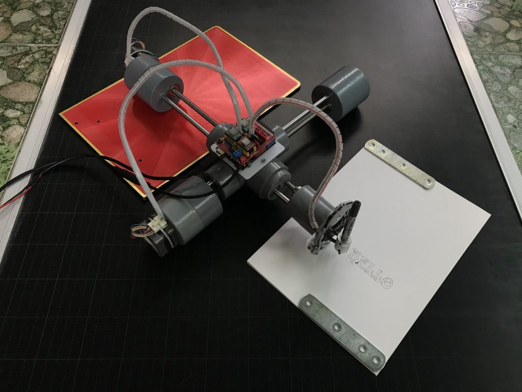
In their quest to create a portable CNC plotter, Instructables user tuenhidiy combined several PVC pieces with a couple of motors to build the P-CNC Plotter. The small machine — which was designed to resemble a quadruped robot — features an Arduino Uno and a Gbrl control shield at its heart that takes incoming G-code and translates it into motor movements. The X axis consists of a single NEMA-17 stepper motor that actuates a threaded rod to slide the rest of the device along a path.
There is a central PVC assembly that holds both the threaded and smooth rods for both the X and Y axes while letting the entire thing move. Tuenhidiy was able to repurpose the linear gliding mechanism from a CD player as the Z axis, thus letting the pen or other drawing utensil go up and down with great precision. A set of three A4988 stepper motor driver modules provide the current to both the NEMA 17 motors and CD drive components.
Images are drawn within the vector-based program Inkscape, and they normally include text, basic shapes, and splines that the toolhead can follow. G-code was exported from Inkscape by using an extension, and this could then be sent to the Gbrl-enabled Arduino. To read more about this project, you can check out tuenhidiy’s write-up here.
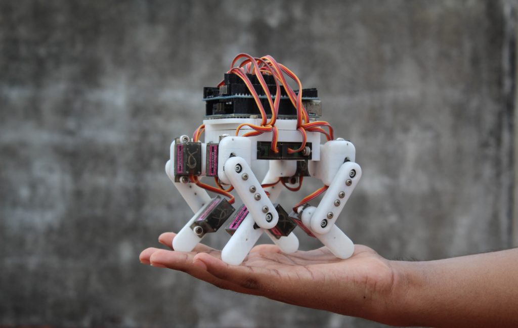
Arduino-powered quadruped robots are quite common projects for hobbyists to build once they are a bit more comfortable with embedded systems. One problem with many of the pre-designed quadruped platforms is that they require a lot of time to assemble owing to their large size. This is what inspired Technovation to come up with their own micro quadruped robot, which requires only a fraction of the normal amount of material and hours to construct.
The robot is based around a central chassis that houses the Arduino Uno and sensor shield components, which provide power and signaling to the motors. Underneath this hardware stack are four servos that can rotate to the side and act as hip joints. Lastly, each leg is comprised of two servos to allow for forward motion.
In order for the Arduino to translate a desired direction into discrete positions for the servo motors, Technovation had to implement a few kinematic equations within the robot’s firmware. These consist of movement functions, which create gaits by specifying where and when each leg should move. Several parameters, including speed, leg length, and even the motion paths themselves, have the ability to be fine-tuned or expanded to add more capabilities.
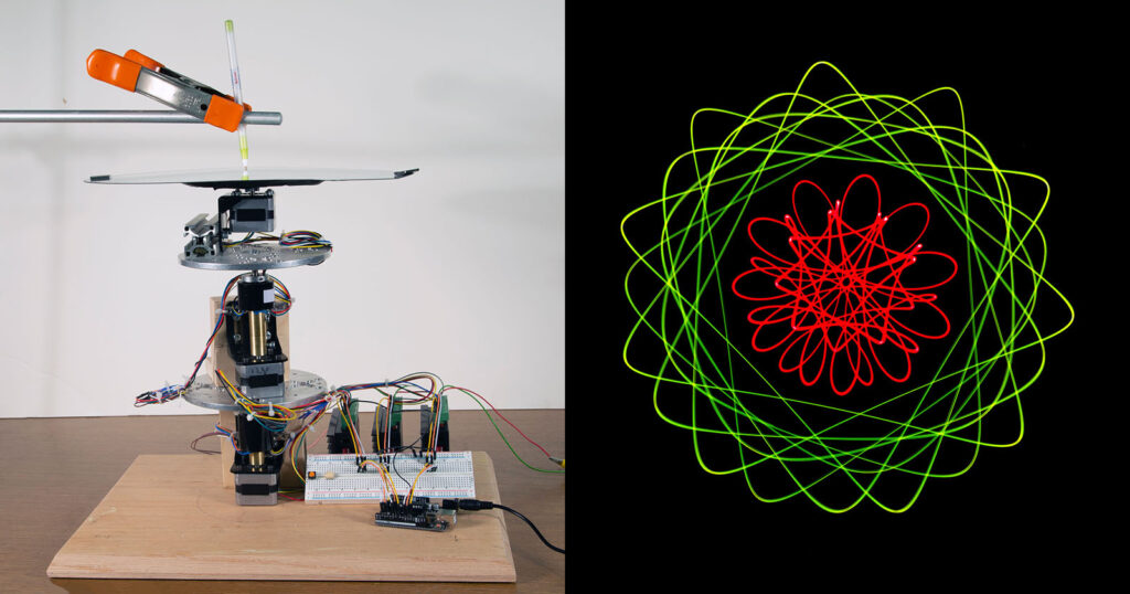
Light painting is a fun way to create digital images by using just a few points of light to “draw” across a camera with a long exposure time. This gives the illusion of a virtual streamer being dragged on the canvas and can produce amazing photos. Ted Kinsman wanted to build a light painting machine, which mimics the geometric chucks from the 1860s that used several spinning platters on a lathe that rotated at different speeds to carve ornate patterns into wood. His version has a series of three platters all stacked on top of each other and are driven by three stepper motors.
A single Arduino Uno runs the program for the geometric light painting machine, and it is responsible for controlling the stepper motors through its three attached TB6660 motor driver modules. The code works by first initializing each stepper as an AccelStepper object and then setting its max speed. The magic comes from this next part, and each motor gets assigned a constant speed value that determines what kind of pattern will be drawn. And finally, the motors are run at these speeds until the machine is stopped. The vast number of combinations from these variables means that even a small change to the motors’ speeds or where the LED is positioned on the top platter can generate wildly different results.
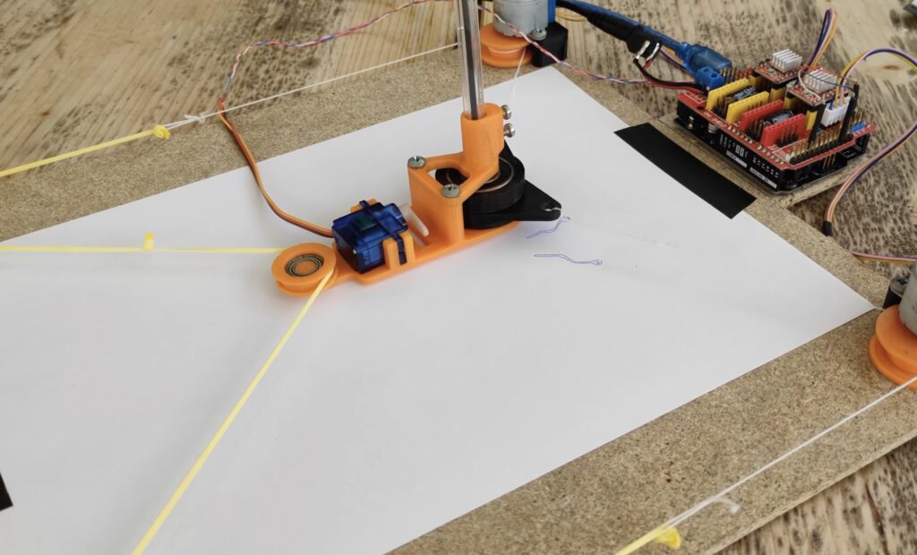
This may be one of the cheapest and easiest CNC drawing machines you’ll find
Arduino Team — July 15th, 2021
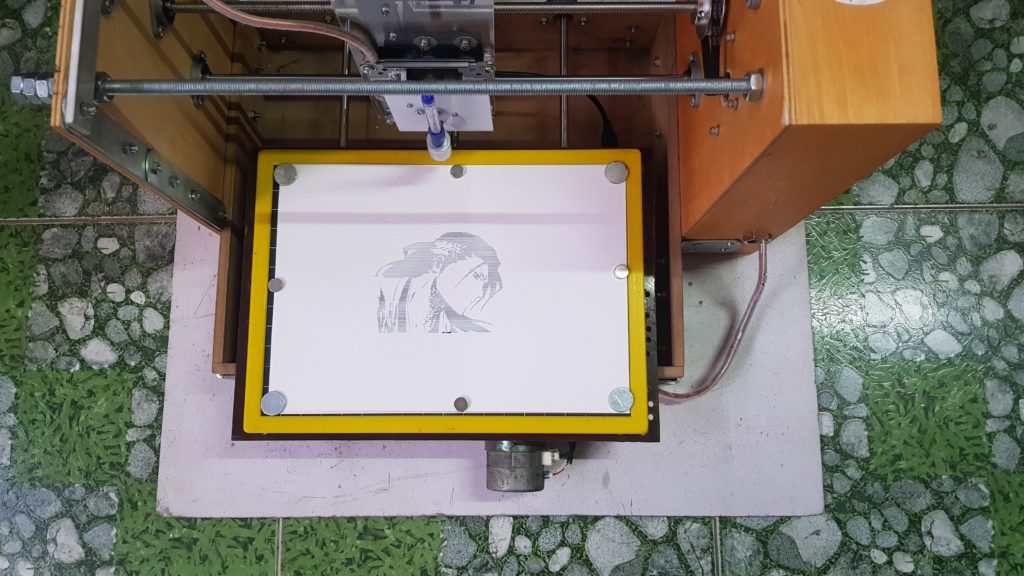
CNC plotters are a lot of fun to build and use, as they teach mechanics, electronics, and how G-code works. However, traditional Cartesian machines often require expensive components such as linear rods and ample amounts of bearings to move in just two axes. YouTuber DAZ Projects set out to change that by assembling a form of a Polargraph to draw pictures with great detail. The idea is simple: use a pair of stepper motors to alter the length of a string on two sides that controls where the toolhead goes.
He started by 3D printing stepper motor mounts, a few pulleys for the string to wrap around, and the pen holding/lifting mechanism. Both 5V stepper motors plug into a generic Grbl CNC shield and are driven by a couple of A4988 modules. The servo is powered directly by an Arduino Uno, and its job is to adjust the pressure the pen applies to the page to define how dark the lines are.
Once the custom firmware written by the Polargraph’s creator, Sandy Noble, was flashed to the Uno, DAZ connected it to his computer which was running the Polargraph control software. In here, the program takes an image and outputs a series of toolpaths for the Uno to convert to motor movements. You can see how DAZ constructed and used the device below, as well as the find the code on GitHub and 3D design files on Thingiverse.
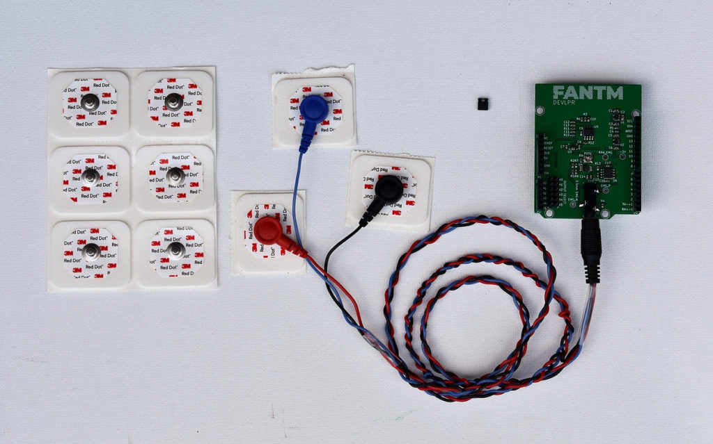
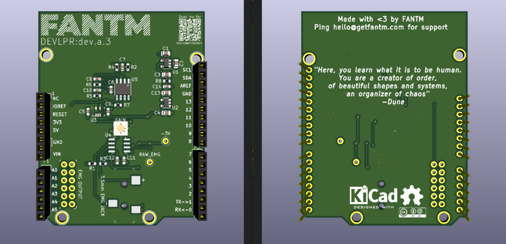
Human-to-computer interfaces are nothing new, but they are often difficult to set up or use in more hobby-oriented applications. The team of Ezra Boley and Finn Kuusisto is setting out to change this with their FANTM EMG Arduino Uno shield. It uses a series of conductive pads that pick up electrical signals from a user’s muscles and feeds that data through a set of filters. Once read by the Arduino’s analog input pin, the values are stored within a buffer for later processing.
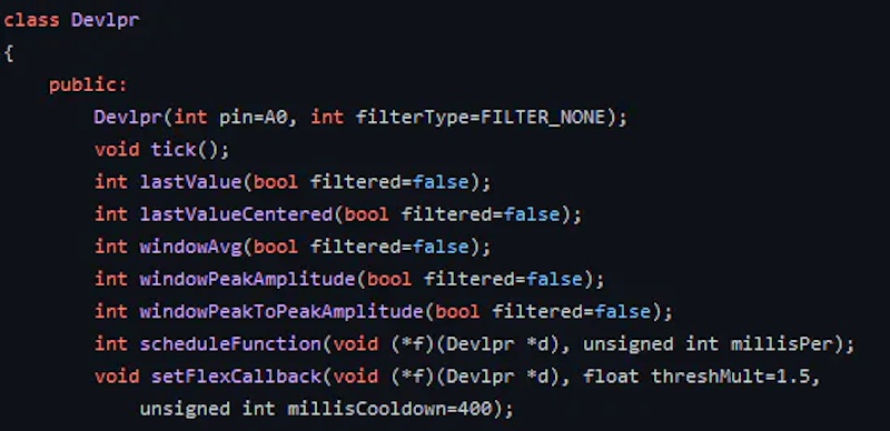
The FANTM DEVLPR shield was designed to be open source, letting makers tinker with its layout, capabilities, and hardware. There is a 3mm jack where sensors can be attached, along with a potentiometer for adjusting the gain of the signal. Up to six shields can be stacked and fed into their own analog input pins. The code is open source too and in the form of an Arduino library for easily dropping into whatever application it might be needed. Users can pass their own callback functions via the API that get called when certain events occur, such as a muscle flexing or after an amount of time has transpired. The API also provides basic statistical methods to retrieve average, peak, and latest values.
To see more about the FANTM DEVLPR Arduino shield, you can visit its website here.
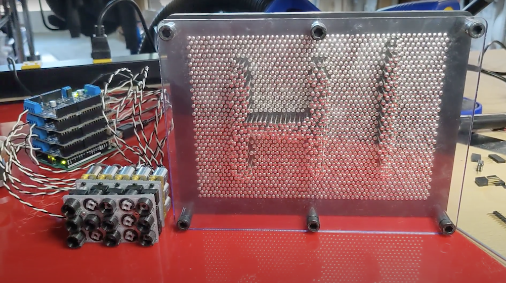
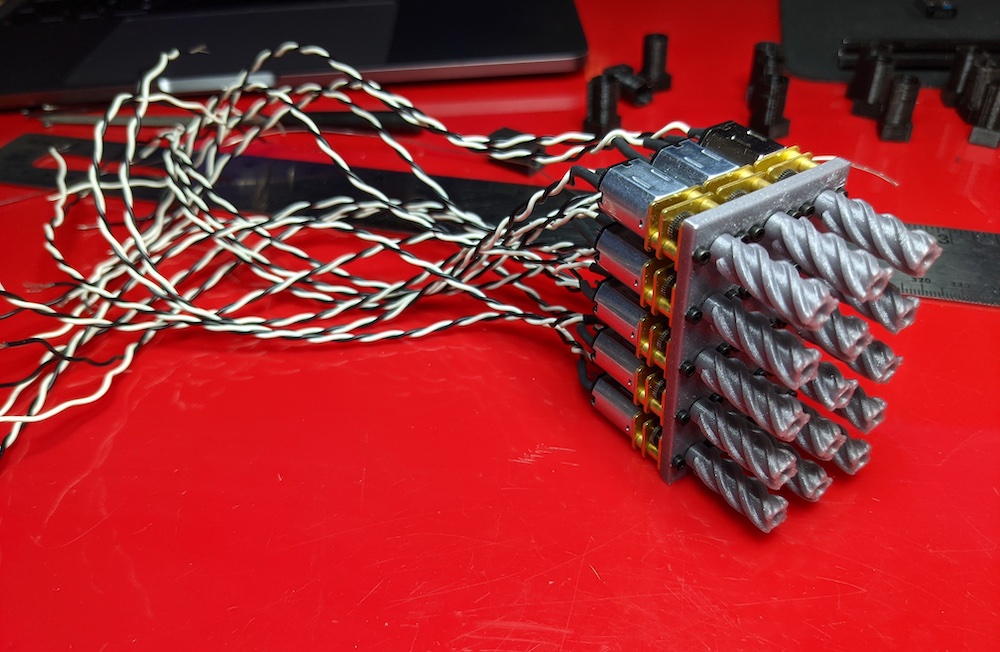
Tactile displays are one of the neatest ways to interact with how data is displayed, as it can not only be seen, but also felt. However, these kinds of systems are often quite expensive due to their complex nature, which is why Jason Higgins wanted to create his own pin display that he calls the PinThing. The device primarily consists of a five by three grid of “pixels” that are each driven by their own geared motor. When the motor turns, it slides a nut along a threaded rod, therefore pushing the pixel in or out.
Nearly the entire project was 3D-printed to keep costs low. This includes the backplate, bracing for the motors, and the threaded rod/nut assembly. Some of the earlier motor prototypes had a built-in homing pushbutton switch, but this was determined to be unnecessary.
A single Arduino Uno sits at the bottom of a stack that consists of two Adafruit Motor Shields, which have the PCA9685 I2C motor driver. This allows the Uno with its limited IO to still control the 15 motors easily. It runs the StandardFirmataPlus firmware and receives commands from a Node.js server over its serial port. In the future, the software could be expanded with extra functionality to draw pictures from a digital image, write text, and more.
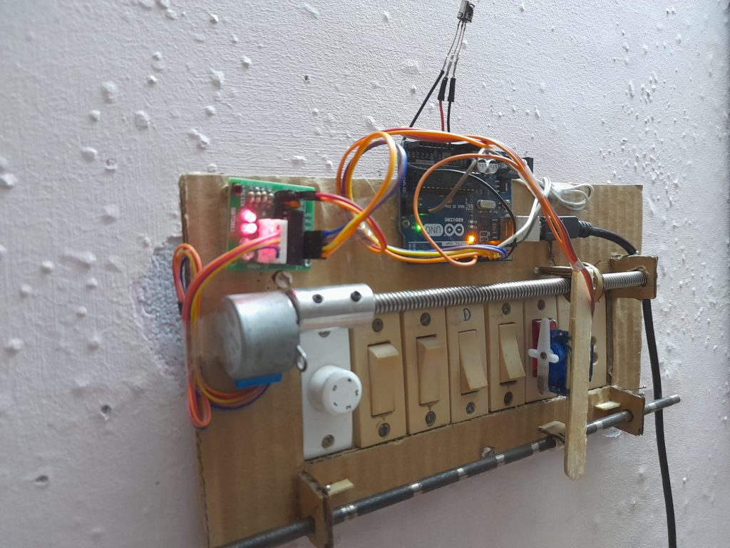
All too often, those who are new to Arduino struggle with creating large projects due to a lack of experience and components. This can be frustrating, but Instructables user MAKE_IT WITH_ME decided to tackle this issue by designing a super cheap way to automate home circuitry from just a single Starter Kit. His build uses a single Arduino Uno, although it can easily be swapped with something like a Nano or Mega, along with a stepper motor/driver, servo motor, threaded rod, and an IR receiver + remote combo.
The main portion of the home automation setup is the stepper motor assembly, and it is responsible for moving the servo motor back and forth across the bank of switches. Due to the stepper motor not knowing its initial position relative to the device, it must be “homed” or set to its zero position by moving right until the edge hits the limit switch. When a request to turn a switch on or off is received from the IR remote, the Arduino board decodes the instruction and converts the command into the number of steps the stepper motor must take to reach the desired location. After the servo moves and flips the switch on or off, the entire thing returns to where it started from.
In the last few years there have been more and more solutions for running machine learning (ML) on microcontrollers. Some of the most popular are scaled down versions of frameworks designed for servers. But those are only suitable for fairly powerful MCUs.
Note: The Fraunhofer IMS is part of the Fraunhofer Society, which currently operates more than 80 research facilities, including 75 institutes, at over 40 locations all over Germany.
Arduino AI Framework Library Is Here
AIfES is a standalone AI framework completely written in C. It allows on-device training without the need for a PC and can be used on almost any hardware. Even on the 8-bit controller of the Arduino Uno, an ANN can be trained pretty quickly. Personal, customized devices can be created that adapt to the task at hand by way of training. AIfES , with Arduino’s support, is now available for the Arduino IDE using theArduino library manager.
This technology allows the development of small, self-learning, battery-powered devices that can be independent of a cloud or another device. Sensor data can be processed where it’s generated, directly on the device. Training data can be recorded by the device and used for training.
AIfES is comparable and compatible with well-known Python ML frameworks. This includes TensorFlow, Keras or PyTorch, while being significantly reduced in functionality. In the current version, feedforward neural networks (FNN) are supported, which can be configured completely freely. Also, common activation functions like ReLU, sigmoid or softmax are already integrated. A full implementation of Convolutional Neural Networks (ConvNet) will follow soon.
The model development is also based on the Python frameworks, so you can find your way around directly. The common algorithms for training, such as the gradient descent optimizer (SGD) or the adam optimizer, are also included.
Import ANNs from Other ML Frameworks
It’s possible to import a previously trained ANN from another ML framework. Only the network structure and weights are needed to map an ANN and train it further. A Keras example is included in the library, and it’s not necessary to port the model to TensorFlow Lite. The weights of an ANN in AIfES can also be read out, saved or sent directly from the device to be used on another device. Different ANNs can be loaded at runtime by reconfiguring the model and loading new weights. The weight sets can be stored in the cloud to make them available to other devices. The applications are endless.
All algorithms are optimized for use on resource-limited embedded systems. Even the required memory area for the ANN can be specified by the developer.
AIfES has been developed in a modular way to be able to exchange different components of the algorithms. A matrix multiplication, for instance. This allows the easy use of hardware accelerators of the different processor families. For example, the CMSIS DSP properties of the ARM Cortex controllers can already be used to compute or train deep neural networks particularly efficiently.
The Fraunhofer IMS has been using AIfES in AI research and development for years. Internally it’s been used as a development tool for customer-specific AI solutions until a level of development was reached where it could be used as a stand-alone product.
Pre-Trained and Adaptable AIfES Gesture Recognition
In gesture recognition, the model was pre-trained and the user performs the gestures as the developer trained them. This is the conventional way, but not very intuitive and the user has to adapt to the hardware. The new demonstrator uses the Arduino Nano 33 BLE Sense, which adapts to the user instead.
The desired gestures can be trained directly in the system without the need for a PC. A first example of product development within industry is the project “noKat“. A neural optical camera tracker for the detection of approaching persons, where a particularly compact human recognition system was realized using AIfES.
Due to their size, deep neural networks (DNN) are problematic for the implementation on a microcontroller. For this reason, Fraunhofer IMS has been researching techniques to realize particularly compact ML solutions for years. Using special feature extraction techniques the number of inputs can be reduced significantly, so only the relevant features are used.
AIfES is offered as a dual license model. For private projects or developers of free open-source software under the GNU General Public License (GPL) version 3, AIfES can be used free of charge. If AIfES is to be combined and distributed with commercially licensed software, or if the AIfES source code for commercially licensed software is not to be distributed under the GNU GPL V3, a commercial license agreement must be concluded with the Fraunhofer IMS. If you’re interested, contact the AIfES team.
AIfES for Arduino includes examples that get you started right away. Besides inference and training, it also shows how to import an ANN from Keras. The Arduino Fruit identification project has been re-implemented in AIfES for the Arduino Nano 33 BLE Sense. Now the colors of three objects are trained directly on the device, without the need for a PC.
We’re super excited about this technology at Arduino, and we can’t wait to see what the community is going to build with it! Make sure you let us know your thoughts, and about any applications you create, over on the forums.
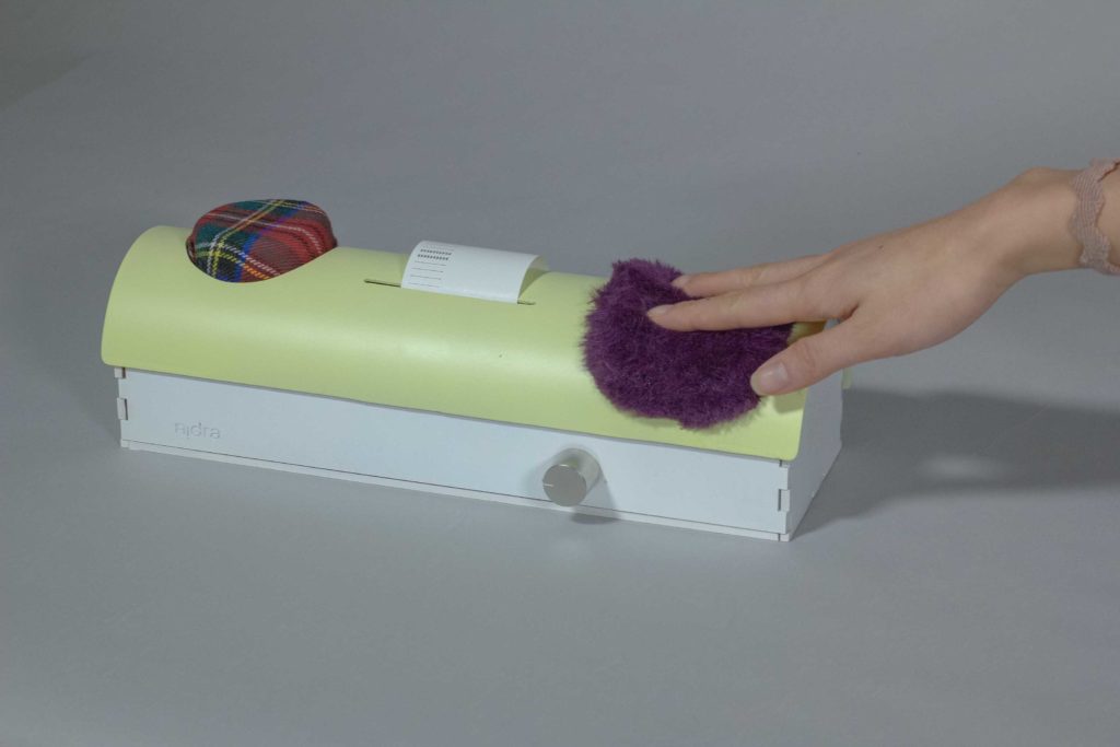
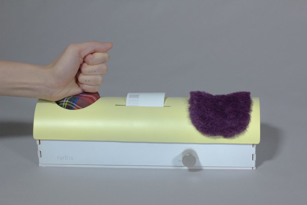
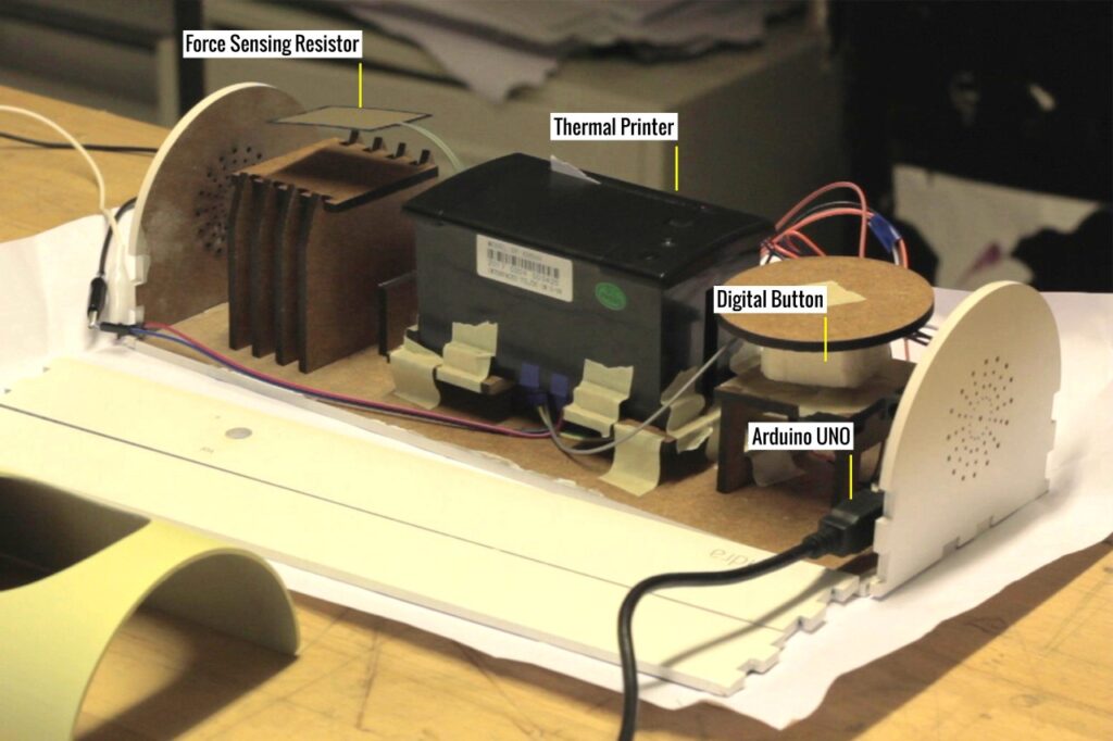
Very few of us are ever excited to wake up for the work day, but your mood can still vary from one morning to the next. If you had a rough night, you might wake up feeling melancholy. In that case, the last thing you want to do is hear depressing news on the radio. To help people enter wakefulness, Varenya Raj built a radio called Nidra that tailors the morning news to suit its user’s mood.
Nidra’s design is unusual, in that it doesn’t resemble any radio or alarm clock that you’ve ever seen. Atop its plastic enclosure there are two buttons. The first looks like a pin cushion and the second seems like it could have come from a shaggy, purple marmot.
If the user is in a bad mood when the alarm goes off, they can slam their hand down onto the cushioned button. Nidra will then play only upbeat news. If the user is in a better mood and can handle the full breadth of the day’s news, they can stroke the purple fur. At the end of the month, a thermal receipt printer pops out statistics on the number of times the user pressed each button.
An Arduino Uno board controls Nidra’s behavior. The cushion has a standard button, while the fur attaches to a force sensitive resistor. Depending on the button pressed, the Arduino sketch tells a connected computer running a Processing sketch to play news from one of two RSS feeds. We imagine that most people will choose the happy news most mornings, but it is always nice to have options.
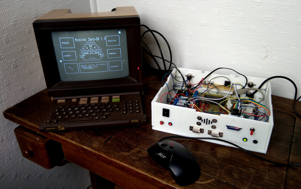
Operating systems are pieces of software that control hardware and software systems within a computer to allow for task scheduling, resource management, and concurrency. Popular OSes included Windows, macOS, GNU/Linux, and Raspbian, but all of these are incapable of running on extremely small processors such as the ATmega328P. That is where ZARDOS, which stands for “Ze ARDuino Operating System,” can help. It is an OS that runs primarily on the Arduino Mega, although its creator says a minimum version can also run on the Arduino Uno.
At the most basic level, ZARDOS communicates with a Minitel 1B or 2 terminal over a single DIN-5 cable via a serial link. Once running, the Arduino board can read in and execute new software via a “cartridge” system, as well as host a filesystem on an SD card. The OS also lets users add a PS-2 mouse, speaker, and videotex printer, which means this device is quite the throwback to the earlier days of home computing.
ZARDOS is a very impressive pieces of software for the Mega, and it will be exciting to see just how far this project goes in the future. To learn more, check out its site here.
EduExo Pro is an Arduino-controlled robotic exoskeleton kit that’s now on Kickstarter
Arduino Team — June 29th, 2021
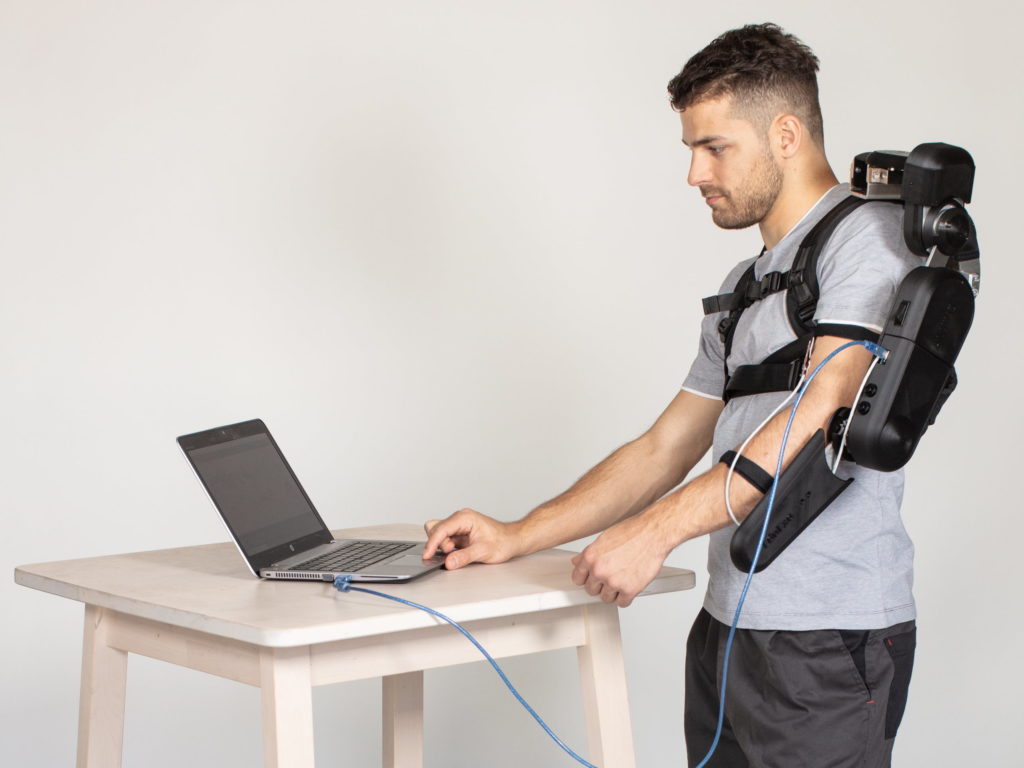
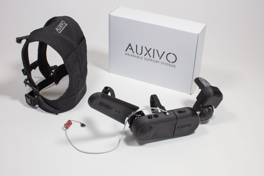
Admit it, you have dreamed of wearing something like Tony Stark’s Iron Man suit. Sadly, that technology is fictional and real world exoskeleton suits are expensive. But a Swiss company called Auxivo wants to make exoskeletons available to educators, students, and hobbyists. To make that happen, they’re releasing their new EduExo Pro wearable robotic exoskeleton kit.
The EduExo Pro is available on Kickstarter to backers in a variety of packages, from a DIY version to a complete, assembled arm. Whichever option you choose, you will end up with a robotic exoskeleton arm that straps onto your own arm to enhance your strength. It has steel load-bearing structural parts and ball bearings on the joints. The shoulder joint has a heavy spring to provide assistance, while the elbow joint utilizes a powerful stepper motor.
An Arduino Uno board controls the stepper motor. It receives data from two sensors: a potentiometer to detect the elbow joint angle and an EMG (electromyography) sensor to monitor bicep muscle activity. The latter can detect when the wearer is flexing their bicep and then push power to the stepper motor. The arm also interacts with software running on a connected computer. For example, the EduExo Pro handbook provides instructions for integrating the arm with a Unity3D virtual reality game.
If you’re interested in trying the EduExo Pro for yourself, the Kickstarter campaign is running until July 29th.
We’ve seen a number of homemade CNC machines throughout the years, but Tuenhidiy’s build — made from some discarded materials — is no less impressive. This unique CNC plotter features a frame cleverly constructed out of two wooden wine boxes, which appear to be the perfect size with space for an Y-axis bed and an upright structure that actuates X movements. For the Z component, a pen is lifted using parts from a recycled CD player drive.
Electronics-wise, the project is also quite interesting as it employs servos rather than steppers for its X and Y axes. Actuation is handled by an Arduino Uno with pre-installed GRBL firmware and a CNC shield, which sends commands to an Arduino Mega running custom firmware. The Mega — plus a custom adapter board and an L293D shield — takes care of PID control for the motors.
More details on the machine can be found in Tuenhidiy’s write-up, and you can see it demonstrated in the video below.
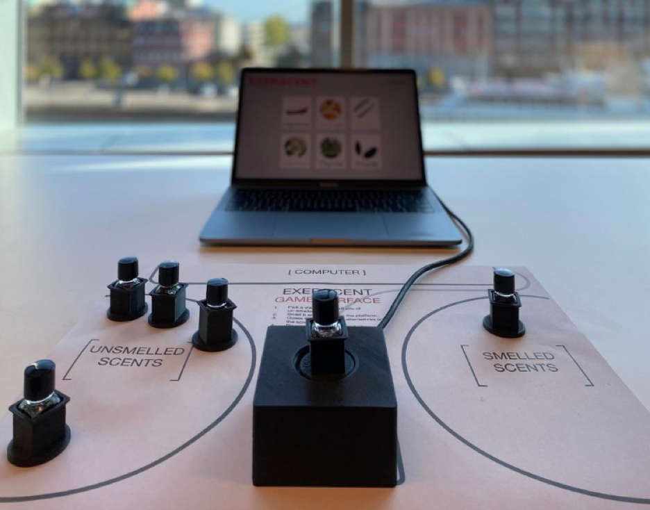
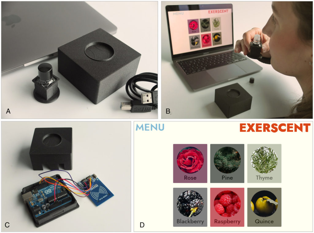
The COVID-19 pandemic has highlighted the need for widespread diagnostic services that can be taken at home, especially those that relate to smell as the loss of that sense is an associated virus side effect. One team from Malmö University and Stockholm University in Sweden has come up with a system they call “Exerscent” that allows patients to test their sense of smell at home using a series of tagged odors that can be adapted over time.
Exerscent uses an Arduino Uno and an MFRC522 NFC reader module to scan various vials of scented liquids and transmit that information to a laptop running the team’s software. Once a smell has been selected, the software guides users on not only which scent to smell first, but also how to handle them. These instructions could include commands such as where to place the vial, how far away it should be from their nose, and what to do once finished.
In the researchers’ study, they had a participant attempt to identify 48 different scents across a 16-day period. Over this time, the subject’s accuracy increased from 81% to 96%, which showcases how powerful this system can be for at-home testing. You can read more about the Exerscent in their paper here.
Images: Niedenthal, S. et al. (2021) ‘A Method for Computerized Olfactory Assessment and Training Outside of Laboratory or Clinical Settings,’ i-Perception. doi: 10.1177/20416695211023953.
Um dir ein optimales Erlebnis zu bieten, verwenden wir Technologien wie Cookies, um Geräteinformationen zu speichern und/oder darauf zuzugreifen. Wenn du diesen Technologien zustimmst, können wir Daten wie das Surfverhalten oder eindeutige IDs auf dieser Website verarbeiten. Wenn du deine Einwillligung nicht erteilst oder zurückziehst, können bestimmte Merkmale und Funktionen beeinträchtigt werden.
Funktional
Immer aktiv
Die technische Speicherung oder der Zugang ist unbedingt erforderlich für den rechtmäßigen Zweck, die Nutzung eines bestimmten Dienstes zu ermöglichen, der vom Teilnehmer oder Nutzer ausdrücklich gewünscht wird, oder für den alleinigen Zweck, die Übertragung einer Nachricht über ein elektronisches Kommunikationsnetz durchzuführen.
Vorlieben
Die technische Speicherung oder der Zugriff ist für den rechtmäßigen Zweck der Speicherung von Präferenzen erforderlich, die nicht vom Abonnenten oder Benutzer angefordert wurden.
Statistiken
Die technische Speicherung oder der Zugriff, der ausschließlich zu statistischen Zwecken erfolgt.Die technische Speicherung oder der Zugriff, der ausschließlich zu anonymen statistischen Zwecken verwendet wird. Ohne eine Vorladung, die freiwillige Zustimmung deines Internetdienstanbieters oder zusätzliche Aufzeichnungen von Dritten können die zu diesem Zweck gespeicherten oder abgerufenen Informationen allein in der Regel nicht dazu verwendet werden, dich zu identifizieren.
Marketing
Die technische Speicherung oder der Zugriff ist erforderlich, um Nutzerprofile zu erstellen, um Werbung zu versenden oder um den Nutzer auf einer Website oder über mehrere Websites hinweg zu ähnlichen Marketingzwecken zu verfolgen.