Safes are designed specifically to be impenetrable — that’s kind of the whole point. That’s great when you need to protect something, but it is a real problem when you forget the combination to your safe or when a safe’s combination becomes lost to history. In such situations, Charles McNall’s safe-cracking autodialer device can help.
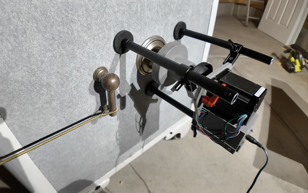
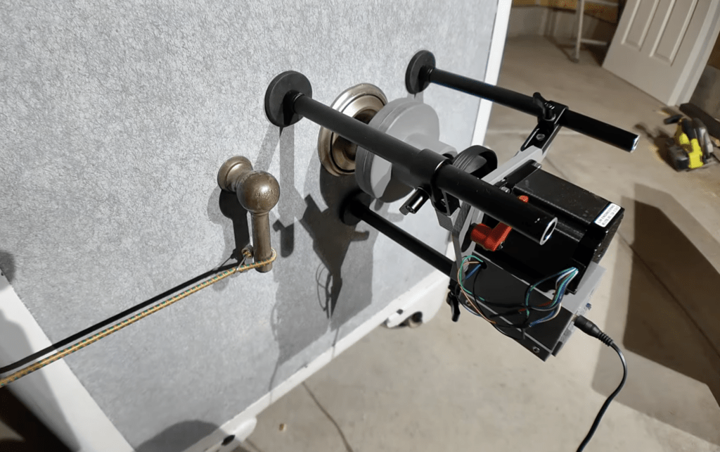
This is a device, controlled by an Arduino UNO Rev3, that can attach to a traditional safe that has a dial combination lock and perform a brute-force procedure in order to find the combination. In simple terms, it tries every permutation of digits until it happens to stumble across the correct combination for that safe.
The Arduino spins the dial using a stepper motor and there is an OLED screen for status information, with buttons for control. The device attaches to the safe using magnetic mounts and it grabs the dial with a 3D-printed chuck. There is also a magnetic clutch, which is important because it slips when the lock mechanism falls into place on a successful combination entry. That prevents the autodialer from continuing on after it finds the correct combination.
This can attempt combinations at a very fast rate, but it could still take several days or even weeks to succeed if it has to try every single permutation. Luckily, it is possible to narrow down the possibilities quite a lot. That depends on the safe model, but design quirks tend to eliminate specific number ranges and can help the cracker find one or two dials through feel alone before moving to brute-forcing.
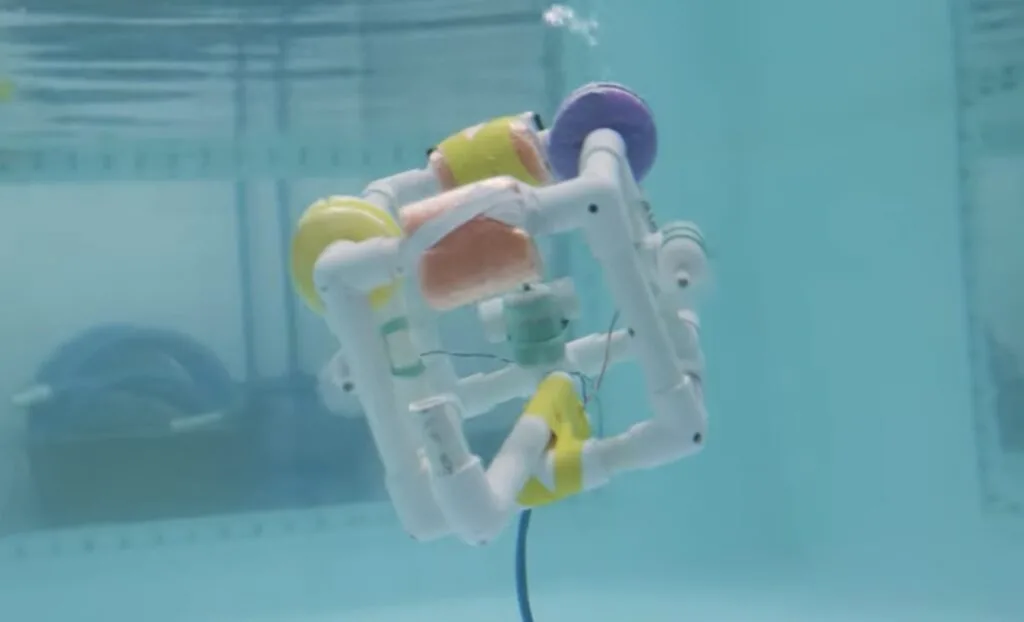
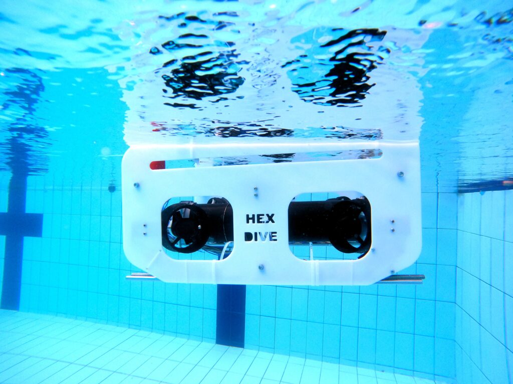
While professionals around the world take advantage of Arduino products and the extensive ecosystem, the core Arduino philosophy is to simplify complex technology. A bare microcontroller is intimidating to the uninitiated, but an Arduino development board is friendly and approachable. MIT’s Sea Grant is harnessing that in their new SeaPerch II underwater ROV (remotely operated vehicle) design that is perfect for students.
The MIT Sea Grant program launched the original SeaPerch initiative way back in 2003 as a way to bring students into the underwater world of ROVs. That original SeaPerch was affordable to build with common parts, but technology has progressed a lot in the past couple of decades and the new SeaPerch II will make use of what the modern scene has to offer.
In particular, SeaPerch II will take a new modular approach for sensors, manipulation, and data collection systems. Those modules are built around Arduino boards for maximum accessibility and flexibility.
SeaPerch II is still in its infancy, but there are already a few modules available that are compatible with the new base ROV.
Module 1, for example, is a “robot whisker sensor” designed around the Arduino UNO family of boards. It is a flexible, waterproof sensor that relies on variable resistance to detect contact with physical objects.
Module 2 is a pressure, depth, and temperature sensor. Once again, the core component is an Arduino board. That monitors an Adafruit LPS35HW pressure sensor sealed inside a balloon. As the depth increases, so does the water pressure outside the balloon. That, in turn, increases the air pressure inside the balloon and the sensor measures the change.
Like the original SeaPerch, SeaPerch II will offer students the chance to become acquainted with underwater ROVs and gain valuable skills along the way.
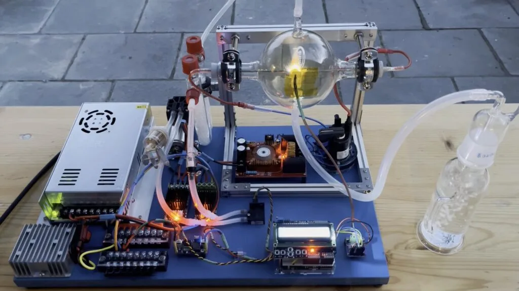
Nitrogen is critical for farming at scale and without some form of nitrogen to enrich the soil, we couldn’t grow staple crops efficiently enough to feed our large global population. Serious science goes into the production of fertilizers and the Birkeland-Eyde process was one early example. It uses electrical arcs to turn nitrogen in the air into nitric acid. Marb is an enthusiastic citizen scientist and built his own experimental reactor to harness the Birkeland-Eyde process.
The Birkeland-Eyde process was largely phased out a century ago, because it is inefficient due to the high energy requirements. It needs a lot of energy to create the electric arcs — too much energy to be practical at the scale necessary for modern industrial farming. But efficiency isn’t a major concern for Marb, who is more interested in the science than fertilizer production.
Creating an electrical arc isn’t very difficult, but controlling it is more challenging. For that reason, Marb used an Arduino UNO Rev3 to oversee his DIY reactor. Through a breakout shield, the Arduino controls the flow of power to the arc electrodes. That requires a large power supply, transformers, and a boost converter.
The rest of the reactor is devoted to the containment, preparation, and flow of air. The Birkeland-Eyde process works best with dry air, so Marb’s design pumps air through a desiccant-packed tube and into the reaction chamber where the electrodes meet. Sensors, like a temperature sensor, help the Arduino gain feedback on the conditions.
Marb’s video ends with a demonstration, but he hasn’t yet refined the reaction process for maximum yields. If there is enough interest, Marb says that he’ll make a follow-up video with more detail.
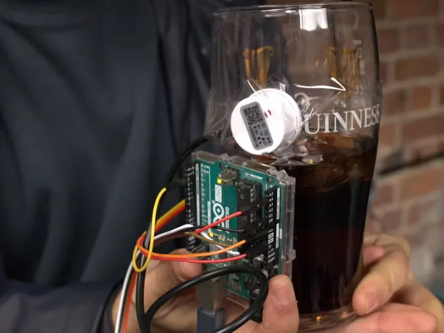
Guinness is one of those beers (specifically, a stout) that people take seriously and the Guinness brand has taken full advantage of that in their marketing. They even sell a glass designed specifically for enjoying their flagship creation, which has led to a trend that the company surely appreciates: “splitting the G.” But that’s difficult for many to pull off, so Eamon Magd built this device that makes the trick easy to master.
“Splitting the G” refers to taking the initial gulp of stout in precisely the right amount to leave the line between liquid and foam in the middle of the “G” on the Guinness logo on a standard Guinness pint glass. Not too difficult for frequent imbibers, but Magd doesn’t usually drink and hasn’t had the practice.
This device solves that problem by vibrating when Magd sips just enough Guinness to result in a split G. It does that with an Arduino UNO Rev3 that monitors the stout in the glass with a non-contact liquid level sensor.
Traditional liquid level sensors, like floats, require physical contact with the contents of the vessel, which can be unsanitary. The sensor chosen by Magd doesn’t, as it relies on capacitive measurements. It attaches to the outside of the glass and can tell if liquid inside the glass is above or below its level.
Magd just had to find the right spot on the glass to attach that sensor and then programmed an Arduino sketch to run the vibration motor when the sensor fails to detect liquid. Magd even plans to put that to the test at the Guinness Storehouse in Ireland.
A small startup called K-Scale Labs is in the process of developing an affordable, open-source humanoid robot and Mike Rigsby wanted to build a compatible hand. This three-fingered robot hand is the result, and it makes use of serial bus servos from Waveshare.
Most Arduino users are familiar with full-duplex serial communication, which requires two data lines. The first carries data in one direction, while the second carries data in the other. As such, devices can send and receive data at the same time — they don’t have to wait to until the line is “free” to send data.
But half-duplex serial communication is also possible. Each device just has to wait its turn to send data. That is less common, but it does have some benefits. In this case, Rigsby used Waveshare servo motors that communicate via a half-duplex serial bus. The benefit is that users can daisy-chain multiple servos together, connecting to a single serial pin on the host device. These particular servo motors also have magnetic encoders instead of potentiometers, which are more reliable.
Five of those servos actuate the 3D-printed fingers on Rigsby’s robot hand (the top two fingers have two joints each). He used an Arduino UNO Rev3 board to control them, but couldn’t use the typical RX and TX (0 and 1) pins for communication over the serial bus. For that reason, he included a serial bus module meant specifically for driving servos like these.
This seems to work pretty well and the motors move smoothly — though they currently lack sensors that would enable force/pressure control.
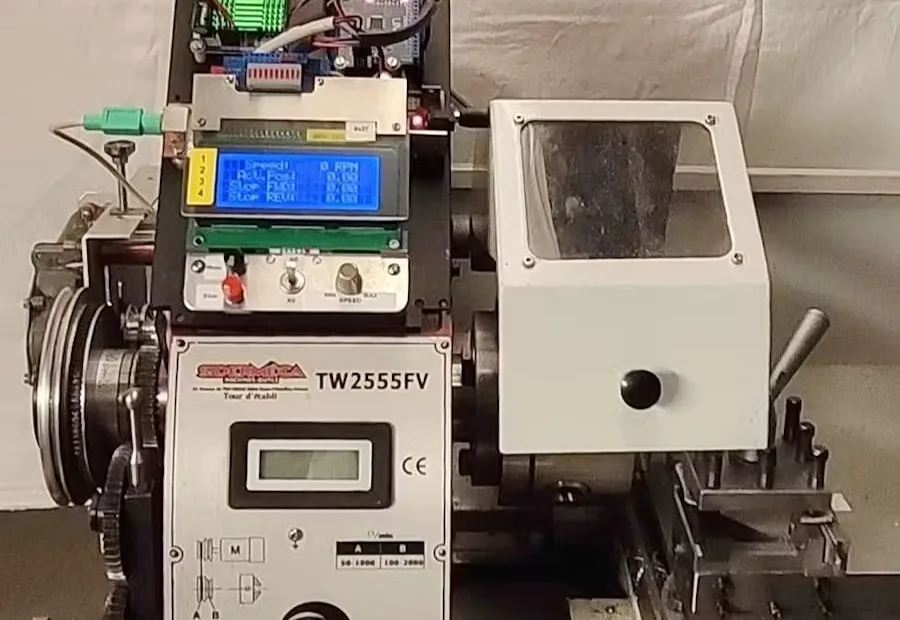
“Single-point threading” on a lathe is the process of cutting threads, such as for a bolt, into the material through turning. The spindle/workpiece spin and the carriage moves linearly at a precise amount per turn of the spindle. That linear movement is the thread pitch. But this process usually requires several passes to reach the final depth, which presents a problem: how do you start each thread at the exact same point each time? Daniel Engel’s Arduino-based mod solves that problem on mini lathes.
To facilitate single-point threading, most lathes have a lead screw that can engage with the carriage in order to move the tool at a constant rate. That lead screw connects to the spindle through “change gears” or a transmission system, letting the machinist adjust the linear travel of the carriage relative to each spindle turn in order to achieve a desired pitch.
But what happens when you finish the first pass and need to go back for a second? How do you keep the leadscrew (and therefore carriage) in sync with the spindle? One method is to run the lathe in reverse, but that has problems of its own. Some lathes have half-nuts designed to sync engagement, but many mini lathes lack that feature.
Engel’s modification does two things to help: first, it provides a gear reduction to the spindle. That lets him perform single-point threading a much lower RPM, increasing torque and making it easier to stop at the right time (such as meeting a shoulder). Second, it lets an Arduino UNO Rev3 board monitor the spindle position via Hall effect sensors that detect four permanent magnets mounted on the spindle from the factory.
The Arduino records the stop and start positions, displaying them on an LCD screen along with the spindle RPM and current position. After finishing a pass, Engel can use that information to return to the exact same starting position in order to perform the next pass.
This is a clever solution to a common problem and Engel’s tutorial has all the information you need to perform the same modification on your own mini lathe.
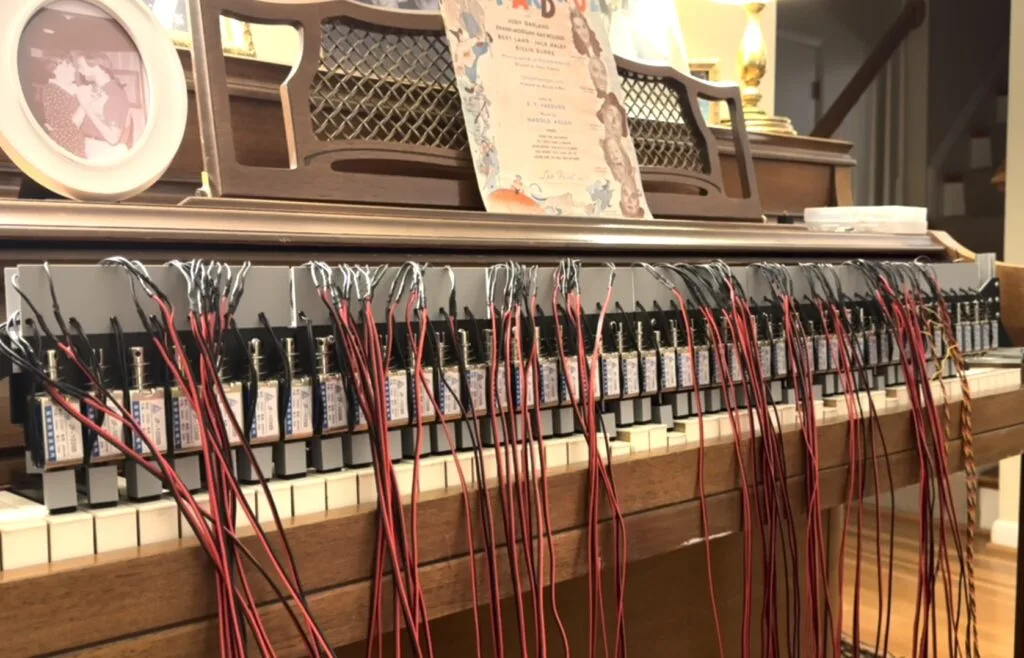
Pianos famously have a lot of keys. A standard full-size piano has 52 white keys and 36 black keys, for a total of 88. Therefore, people need to get clever when they build self-playing pianos. However, the brute force approach works, too. Paul Junkin’s brute force strategy was to add a solenoid for every one of those 88 keys on his piano-playing robot.
Junkin built this robot to play an old piano that had been in his family’s home since his childhood. For that reason, he didn’t want to do any permanent modifications to the piano itself and instead designed the robot to sit over the keys. It has a frame made of aluminum extrusion to support all of those solenoids.
They are 12V solenoids that can push with 25 newtons of force. An Arduino UNO Rev3 drives those solenoids through PWM modules and power MOSFETs. The PWM control lets the Arduino output something effectively approximating analog voltage in order to adjust the velocity of each key strike.
To tell the Arduino which keys to strike and with what velocity, Junkin used a USB-to-MIDI adapter going from his laptop to a MIDI-to-serial converter that connects to the Arduino. Software on the computer sends MIDI note commands through those adapters to the Arduino, which then actuates the solenoids accordingly.
This turned out well and the robot is able to play songs perfectly. And, best of all, it would be possible to put this robot on any other piano of a similar size.
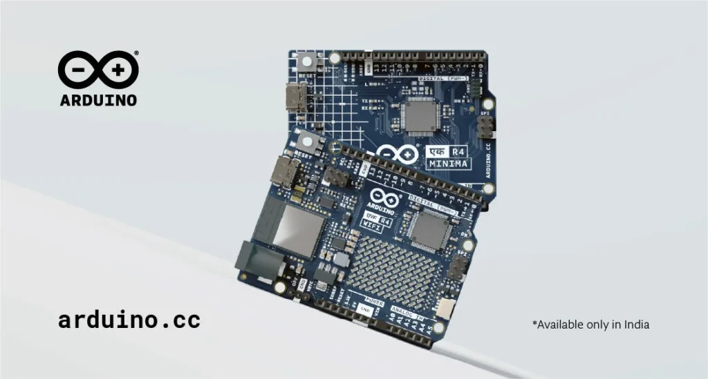
We are proud to announce the Made-in-India UNO Ek R4! Available exclusively in India in both WiFi and Minima variants, it is born to meet the needs of the country’s growing maker and innovation ecosystem, by combining all the powerful features of the UNO R4 with the benefits of local manufacturing, enhanced availability, anddedicated support for Indian users.
Uno, one, Ek ! In case you are wondering, Ek means “one” in Hindi, symbolizing unity and simplicity. It represents the Arduino UNO’s position as the foundation of countless maker projects – simple yet powerful, and always the first step toward innovation. To pronounce Ek, say “ake” (rhymes with “bake”) with a soft “k” sound at the end.
Supporting innovation in India
The two new boards were developed under the “Make in India” campaign, launched to make India the global design and manufacturing hub, and are being launched as part of the country’s Republic Day celebrations. They were first unveiled at the World Economic Forum 2025 in Davos, where they were presented to Shri Ashwini Vaishnav, India’s incumbent Minister of Electronics and Information Technology, and Mr Jayant Chaudhary, Minister of State (IC) for the Ministry of Skill Development & Entrepreneurship. The event was an outstanding opportunity to reflect on India’s huge role in technological innovation and open-source initiatives, with a focus on fostering STEM education and advancing the maker community.
Fabio Violante, CEO (right), and Guneet Bedi, SVP and General Manager (left) with Shri Ashwini Vaishnaw, Minister of Electronics and IT (center).
Fabio Violante, CEO (right), and Guneet Bedi, SVP and General Manager (left) with Mr Jayant Chaudhary, Minister of State (IC) for the Ministry of Skill Development & Entrepreneurship (center).
We are committed to empowering the thriving maker and engineering community in India – the second country in the world for Arduino IDE downloads, just to mention one important statistic! As our CEO Fabio Violante shares,“Arduino’s decision to manufacture in India reflects the nation’s immense potential as a rising global leader in technology. This step embodies our deep belief in the power of collaboration and community. By joining forces with Indian manufacturers, we aim to ignite a culture of innovation that resonates far beyond borders, inspiring creators and visionaries worldwide.”
Why choose UNO Ek R4 boards?
The UNO Ek R4 WiFi and UNO Ek R4 Minima offer the same powerful performance as their global counterparts, featuring a 32-bit microprocessor with enhanced speed, memory, and connectivity options. But the Made-in-India editions come with added benefits tailored specifically for Indian users, including:
Faster delivery: Locally manufactured boards with extensive stock ensure reduced lead times for projects of all sizes.
Affordable pricing: Genuine Arduino products made accessible at competitive prices.
Local support: Indian users gain access to official technical assistance alongside Arduino’s vast library of global resources.
Sustainable manufacturing: Produced ethically with eco-friendly packaging and certified to SA8000 and FSC standards.
Guneet Bedi, Arduino’s Senior Vice President and General Manager of the Americas, comments: “By adding the Arduino UNO Ek R4 WiFi and Arduino UNO Ek R4 Minima to our product line, Arduino is helping to drive adoption of connected devices and STEM education around the world. We’re excited to see the creative projects this community can create with these new boards.”
The past and the future are Ek
The strong legacy of the UNO concept finds a new interpretation, ready to leverage trusted Arduino quality and accessibility to serve projects of any complexity – from IoT to educational applications to AI.
Catering more closely to local needs, UNO Ek R4 WiFi and UNO Ek R4 Minima are equipped to drive the next wave of innovation in India. Both will be available through authorized distributors across the country: sign up here to get all the updates about the release!
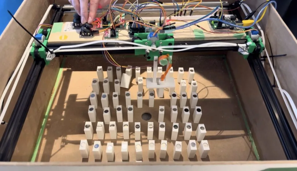
Server rooms are built for the comfort of servers — not people. But those servers need maintenance, which means they need to be accessible. The resulting access corridors take up room that could be filled with more servers, which is why Jdw447 designed a claw machine-esque ‘modular server room’ and built a working scale model to demonstrate the concept.
This isn’t necessarily a serious proof of concept, as there would be a lot more to consider on top of simply moving the servers to an accessible location. But it is a novel idea that Jdw447 actually brought to life in the form of a relatively small model based on Oliver Shory’s gantry design. It is a bit like a claw machine mixed with a plotter. At actual server room scale, it would look like an overhead gantry crane. Here, it looks a bit like the motion system on a laser cutter.
The gantry is made of aluminum extrusion and 3D-printed joints. It has four stepper motors to move the gantry and to actuate the lifting mechanism, which grabs the model server racks using magnets. An Arduino UNO Rev3 board controls those motors through ULN2003 drivers, and the operator directs the movement using joysticks monitored by the Arduino.
This motion system sits in a large MDF box representing a server room, with several 3D-printed blocks representing the server racks arranged in a grid. When a “server” needs maintenance, the operator can use the gantry to pick it up and move it to the desired location.
2011’s Real Steel may have vanished from the public consciousness in a remarkably short amount of time, but the concept was pretty neat. There is something exciting about the idea of fighting through motion-controlled humanoid robots. That is completely possible today — it would just be wildly expensive at the scale seen in the movie. But MPuma made it affordable by scaling the concept down to Rock ‘Em Sock ‘Em Robots.
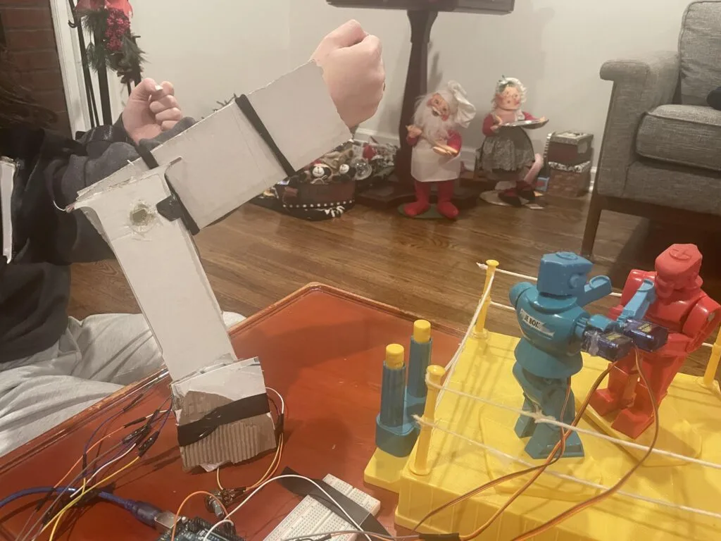
The original Rock ‘Em Sock ‘Em Robots toy was purely mechanical, with the players controlling their respective robots through linkages. In this project, MPuma modernized the toy with servo motors controlled via player motion.
As designed, the motion-controlled robot has three servo motors: one for the torso rotation, one for the shoulder, and one for the elbow. If desired, the builder can equip both robots in that manner. An Arduino UNO Rev3 board controls those motors, making them match the player’s movement.
The Arduino detects player movement through three potentiometers — one for each servo motor. Twisting the elbow potentiometer will, for example, cause the robot’s elbow servo motor to move by the same angle. That arrangement is very responsive, because analog potentiometer readings are quick. It is, therefore, suitable for combat.
The final piece of the puzzle is attaching the potentiometers to the player’s body. MPuma didn’t bother with anything complicated or fancy, they just mounted the potentiometers to pieces of cardboard and strapped those to the player’s arm.
This may not be as cinematic as Real Steel’s robots, but you can recreate MPuma’s project for less than you spent to see that movie in theaters.
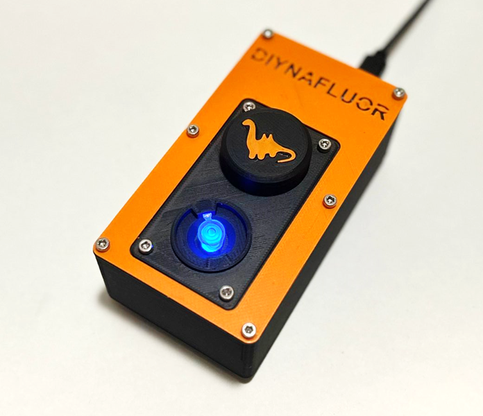
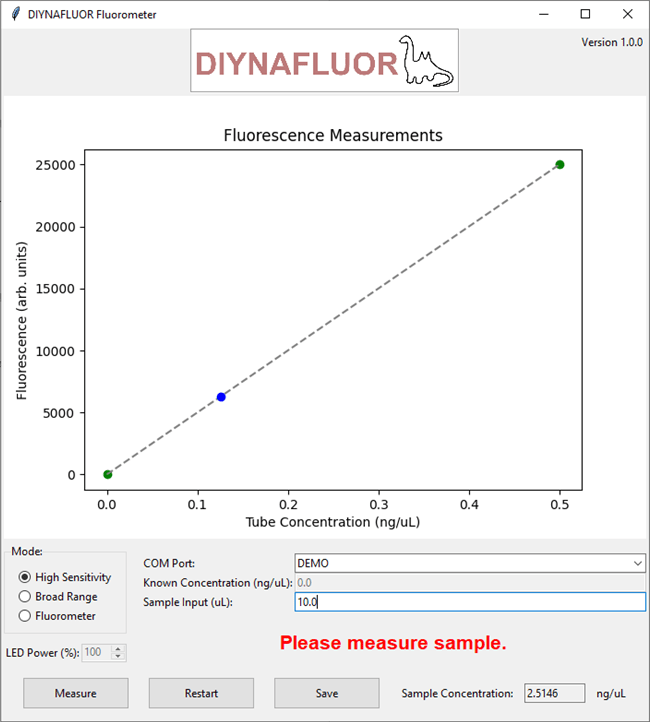
Lab equipment is — traditionally at least — tremendously expensive. While there are understandable reasons for those costs, they are prohibitive to anyone operating outside of a university or corporate lab. But as the “citizen science” movement has grown, we’ve seen more and more open-source and affordable designs for lab equipment hitting the internet. The latest will be interesting to anyone who wants to do work with DNA or RNA: the DIYNAFLUOR.
DINYAFLUOR stands for “DIY Nucleic Acid Fluorometer,” which describes this device’s function. A fluorometer is a piece of equipment the measures the amount of light emitted by anything that fluoresces. In this context, that would be a reagent that increases in fluorescence when it comes into contact with the nucleic acid in DNA or RNA. The more light the fluorometer detects, the more nucleic acid is present in the sample. Sensitivity is important, which is part of the reason that fluorometers are expensive (usually several thousand dollars for basic models).
The DIYNAFLUOR, on the other hand, only costs about $40 to build. It works with both custom and commercially made fluorescent DNA quantification kits and can measure DNA on the scale of nano-micrograms.
This is affordable because its designers built it around off-the-shelf components that are easy to source and a 3D-printable enclosure. The primary component is an Arduino UNO Rev3 board, which looks at the sample through a TSL2591-based light sensor. An LED puts out 470nm light to excite the reagent and optical filters remove the unwanted wavelengths. User-friendly software with a simple GUI lets citizen scientists take measurements and record data directly to their computers.
This may be a specialized device with narrow appeal. But for those who want to work with DNA or RNA outside of a “real” lab, the cost and performance of DIYNAFLUOR is unbeatable.
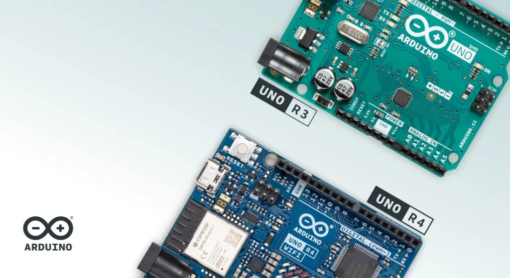
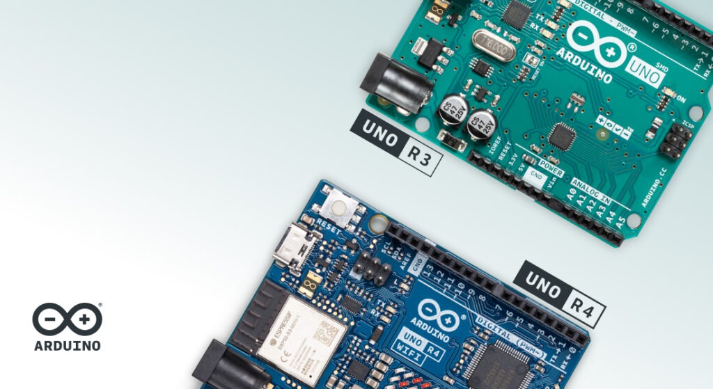
The Arduino UNO is legendary among makers, and with the release of the UNO R4 in 2023, the family gained a powerful new member. But with two incredible options, which UNO should you pick for your project? Here’s a breakdown of what makes each board shine, depending on your needs, skills, and goals.
Why the UNO Rev3 is still a go-to classic
The UNO Rev3 has been around for over a decade, earning its reputation as a solid, reliable board perfect for beginners. Simple, robust, and versatile, it’s the “base camp” of the Arduino ecosystem. Its 8-bit architecture makes it straightforward to understand exactly what’s happening in your code.
Applications and ideal uses
The UNO Rev3 is fantastic for projects like controlling LEDs, motors, and simple sensors – as well as any of the 15 projects included in our best-selling Arduino Starter Kit.
Its ability to handle a higher current directly from each pin makes it ideal for connecting power-hungry sensors or motors without needing extra components. It’s also compatible with an enormous number of sketches and libraries that have been built around it over the years.
One key advantage? The microcontroller on the UNO Rev3 can be removed, allowing you to use it independently – a feature that many seasoned users love.
The UNO R4 builds on everything makers love about the Rev3, adding features that bring it up to speed with the needs of today’s tech. Its 32-bit Arm® Cortex®-M4 guarantees significantly faster processing power and can handle more advanced projects. It comes in two versions: the UNO R4 Minima for essential functionality and the UNO R4 WiFi for Internet-connected projects.
The latter is the brains of the Plug and Make Kit: the easiest way to go from zero to tech hero, with step-by-step tutorials to create a custom weather station, a video game controller, a smart timer and so much more!
Advanced features for new possibilities
The UNO R4 packs in features that are groundbreaking for the UNO family:
12-bit DAC: Enables analog output for audio waveforms or other analog components without external circuitry.
CAN bus: Ideal for connecting multiple devices in robotics or automotive projects.
Wi-Fi® and Bluetooth® on the R4 WiFi model: Easily build IoT projects and connect to the Arduino Cloud to control your devices remotely.
Enhanced Diagnostics: The R4 WiFi includes an error-capturing mechanism that helps beginners by identifying issues in the code, a fantastic learning tool.
Applications and ideal uses
With increased memory and processing power, the UNO R4 is perfect for projects that require complex calculations or manage multiple processes. Think IoT, data sensing, automation systems, creative installations or scientific equipment where precise measurements and real-time adjustments are key.
What’s more, the UNO R4 has the capability to leverage AI – and our community has jumped at the chance of exploring whole new realms. One user built a gesture recognition system made of cardboard, another added smart detection to a pet door to always know if their cat was home or not, and another yet came up with a great tool to always know what song is playing. Not to mention the possibilities for advanced animationslike this one – inspired by Bad Apple – developed thanks to the LED matrix right on the UNO R4.
Is a 32-bit MCU always better than an 8-bit?
The short answer is, no. We believe the best solution is always determined by the requirements of the project at hand: bigger, faster, more powerful or more expensive is not always better.
8-bit microcontrollers process data in 8-bit chunks, which limits the size of numbers they can handle directly to values between 0 and 255 (or -127 and 128). This limitation makes them best suited for applications with minimal data processing needs, such as basic tasks like toggling LEDs or controlling simple sensors. However, they also tend to be more affordable and to consume less power, making hardware design less expensive, and have a simpler architecture, which translates to easier programming. So, if you are still learning the basics and need the most straightforward tool, or you are tackling a project with minimal requirements, an 8-bit MCU is not only all you need, but probably your best option.
On the other hand, if you need to work on much larger numbers and perform data-heavy calculations, 32-bit microcontrollers can handle advanced applications like image processing and real-time analytics. The difference is not just 4-fold going from 8 to 32: it’s a huge jump from 255 to 4,294,967,295! Almost by definition, any solution that requires this kind of performance will be more complex to design and program, require more memory, and consume more power, often affecting battery life. The upside, of course, is the incredible potential of what you can achieve!
Compatibility and transitioning from UNO Rev3 to UNO R4
If you already have experience with the UNO Rev3 and are considering the R4, but have concerns about compatibility, rest assured: they have the same form factor, pinout, and 5V operating voltage. This makes it easy to transfer accessories such as shields from one to the other.
On the software side, tutorials and projects are often compatible. We have even created a GitHub repository where you can check compatibility for libraries with the new R4 (and even help us update information or add new R4-friendly versions). This is part of the effort we share with our community to make sure that transitioning to the UNO R4 – if you choose to do so – is as seamless as possible.
Which Arduino UNO should I choose?
UNO Rev3
UNO R4
• Best for beginners or those working on foundational projects.
• Great for educational settings, where understanding core programming concepts and hardware interactions are the focus.
• Ideal if you need a reliable, budget-friendly, no-frills board with vast project resources available online.
• Perfect for advanced users or beginners looking to push boundaries with more complex projects.
• Best for IoT, data-intensive, or networked applications that require more processing power.
• A smart choice if you’re experimenting with new peripherals like CAN bus, DAC, or Wi-Fi/Bluetooth connectivity.
Choose your UNO and start creating!
Whether you choose the classic UNO Rev3 or the more recent UNO R4, you’re joining a global community of makers, educators, and inventors who love to create. Both boards offer incredible opportunities, each tailored to different stages and styles of making. Ready to dive into a new project? Buy your next UNO and discover limitless possibilities!
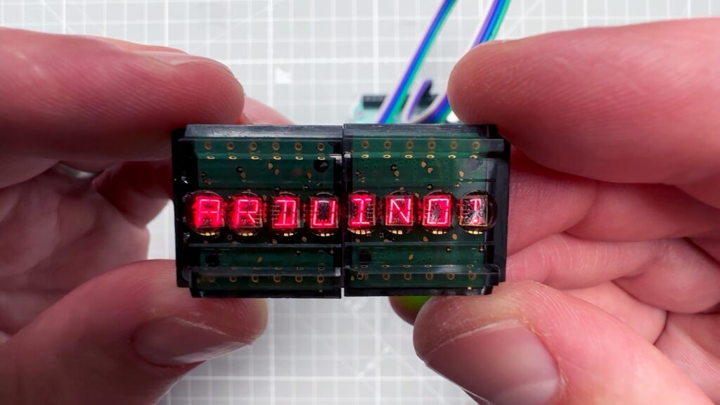
If you want to add a display to your Arduino project, the easiest solution will likely be an LCD or OLED screen. But though those are affordable and work really well, they may not provide the vibe you’re looking for. If you want a more vintage look, Vaclav Krejci has a great tutorial that will walk you through using old-school LED bubble displays with your Arduino.
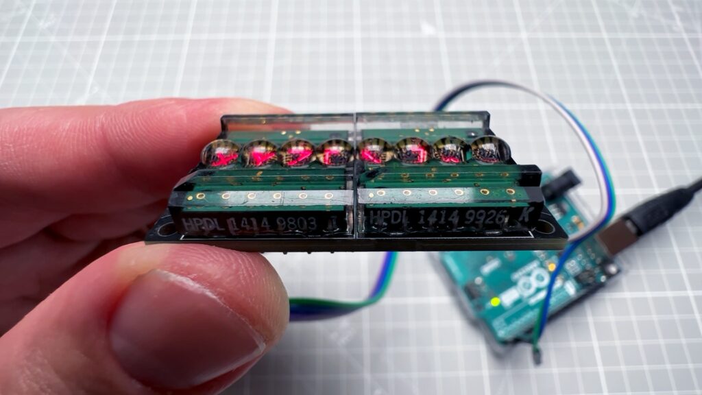
Krejci’s video demonstrates how to use HPDL-1414 displays, which are what most people call “bubble” displays, because they have clear bubble-like lenses over each character’s array of LEDs. They were fairly popular in the late ‘70s and ‘80s on certain devices, like calculators. These specific bubble displays can show the full range of alphanumeric characters (uppercase only), plus a handful of punctuation marks and special symbols.
The HPDL-1414 displays Krejci used come on driver boards that set the characters based on serial input. In the video, Krejci first connects those directly to a PC via a serial-to-USB adapter board. That helps to illustrate the control method through manual byte transmission.
Then Krejci gets to the good stuff: connecting the HPDL-1414 bubble displays to an Arduino. He used an Arduino UNO Rev3, but the same setup should work with any Arduino board. As you may have guessed based on the PC demonstration, the Arduino controls the display via Serial.print() commands. The hex code for each character matches the standard ASCII table, which is pretty handy. That makes it possible to Serial.write() those hex codes and even Serial.write() the actual characters.
Don’t worry if that sounds a little intimidating, because Krejci has sample code that will let you easily turn any arbitrary array of characters into the serial output you need. Now you can use those awesome bubble displays in your own projects!
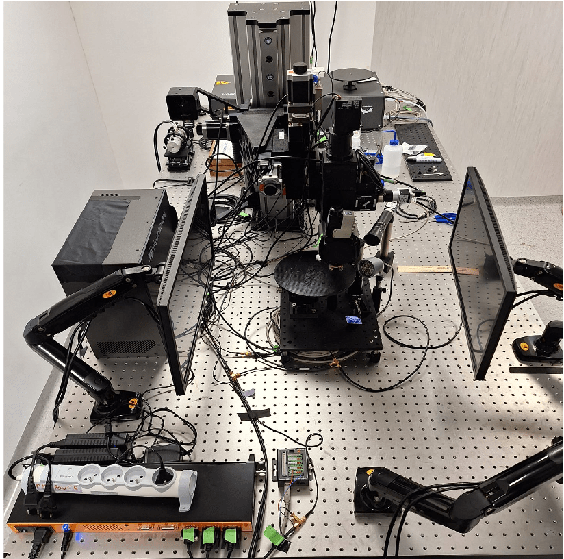
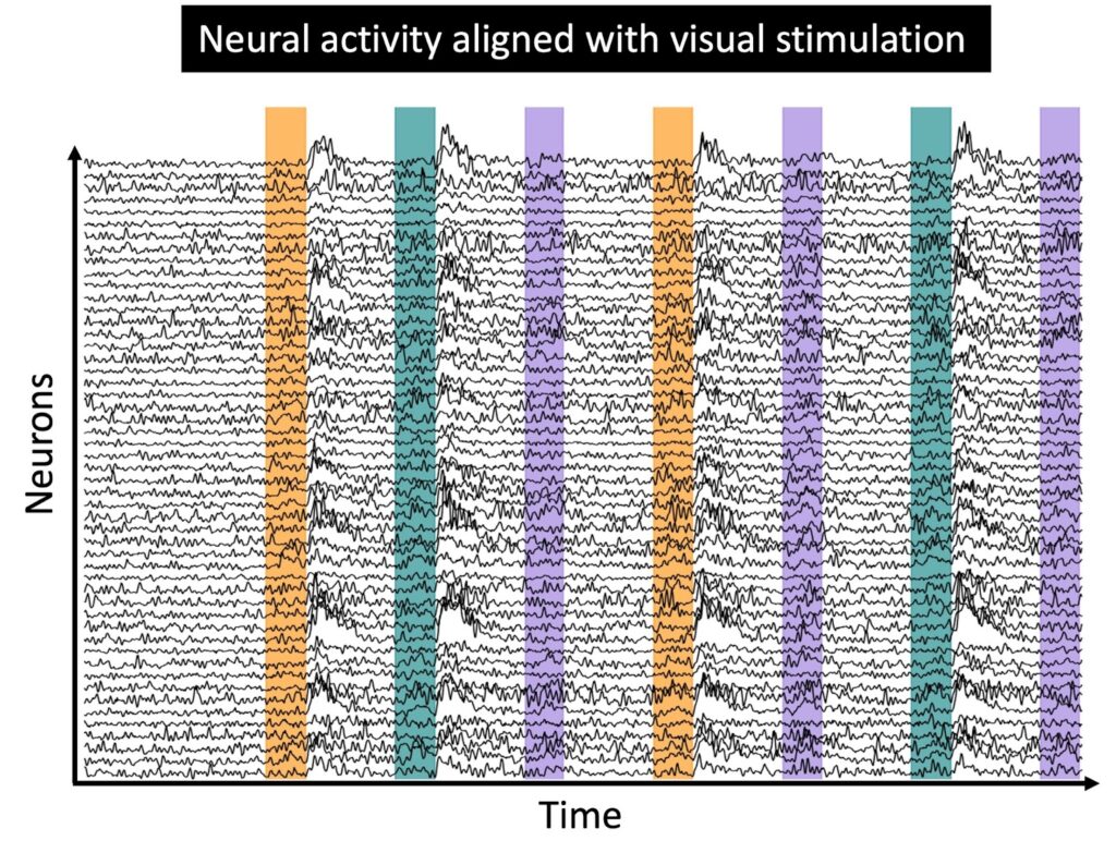
Common research methods to study the visual system in the laboratory include recording and monitoring neural activity in the presence of sensory stimuli, to help scientists study how neurons encode and respond, for example, to specific visual inputs.
One of the biggest technical problems in the neural recording setups used in such experiments, is achieving precise synchronization of multiple devices communicating with each other, including microscopes and screens displaying the stimuli, to accurately map neural responses to the visual events.
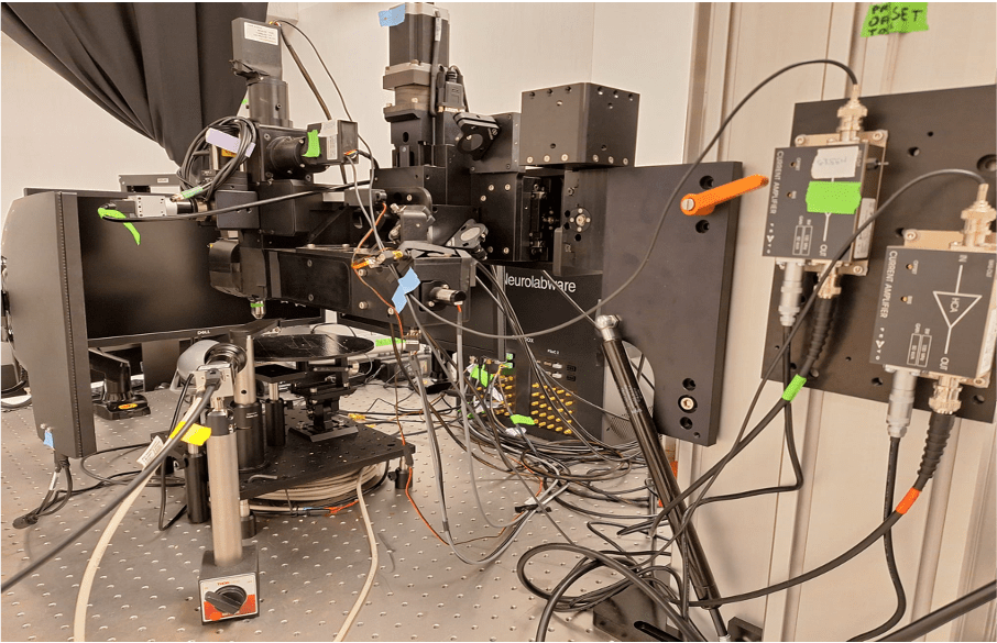
For example, in the Rompani Lab, a visual neuroscience laboratory at the European Molecular Biology Laboratory (EMBL) in Rome, the recording system (a two-photon microscope) needs to communicate with the visual stimulation system (composed of two screens) that are used to show visual stimuli while recording neural activity. To synchronize these systems efficiently, they turned to an Arduino UNO Rev3. “Its simplicity, reliability, and ease of integration made it an ideal tool for handling the timing and communication between different devices in the lab,” says Pietro Micheli, PhD student at EMBL Rome.
How the setups works
The Arduino UNO Rev3 is used to signal to the microscope when the stimulus (which is basically just a short video) starts and when it ends. While the microscope is recording and acquiring frames, a simple firmware tells the UNO to listen to the data stream on a COM port of the computer used to control the visual stimulation.
Within the Python® script used for controlling the screens, every time a new stimulus starts a command is written on the serial port. The microcontroller reads the command, which can be either ‘H’ or ‘L’, and sets the voltage of the output TTL at pin 9 to 5V or 0V, respectively. This TTL signal goes to the microscope controller, which generates time stamps for the microscope status. These timestamps contain the exact frame numbers of the microscope recording at which the stimulus started (rising edge of the TTL) and ended (falling edge of the TTL).
All this information is essential for the analysis of the recording, as it allows the researchers at EMBL Rome to align the neural responses recorded to the stimulation protocol presented. Once the neural activity is aligned, the downstream analysis can begin, focusing on understanding the deeper brain activity.
Ever wonder what neurons that are firing look like?
Micheli shared with us an example of the type of neural activity acquired during an experimental session with the setup described above.
The small blinking dots are individual neurons recorded from the visual cortex of an awake, behaving mouse. The signal being monitored is the fluorescence of a particular protein produced by neurons, which indicates their activity level. After the light emitted by the neurons has been recorded and digitised, researchers extract fluorescence traces for each neuron. At this point, they can proceed with the analysis of the neural activity, to try to understand how the visual stimuli shown are actually encoded by the recorded neural population.
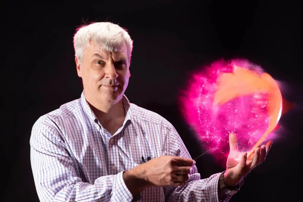
In the world of photography, the exposure triangle is immutable. To get a properly exposed photo (not too bright or too dark), you need a balance of aperture size (how much light gets in), shutter speed (how long the light gets in), and ISO (sensitivity to light at the expense of noise). But the shooting situation often limits how the photographer can adjust each parameter. To freeze action, for example, you need a very fast shutter — reducing the light you let in and therefore exposure. To compensate, you might need to use a flash and this DIY device can help with the timing.
There is a reason that photography flash units only come on for a split second (about 1/10,000th of second is normal): they’re incredibly bright and would burn out if left on for any length of time. To freeze action, such as a balloon popping, you need a fast shutter speed. Too slow and the photo will be all blurry. Exact numbers vary, but 1/8,000th of a second isn’t unusual for the mechanical shutter on a modern mirrorless camera. To get proper exposure, you need to time the shutter to open at the exact same time that the flash is illuminating your subject and that is something you could never achieve through manual control.
That’s hardly a new problem and so cameras are capable of releasing the shutter at the proper time in relation to the flash, but how do you sync those two events with whatever action you want to freeze? If that action happens to make a noise, this device is the solution.
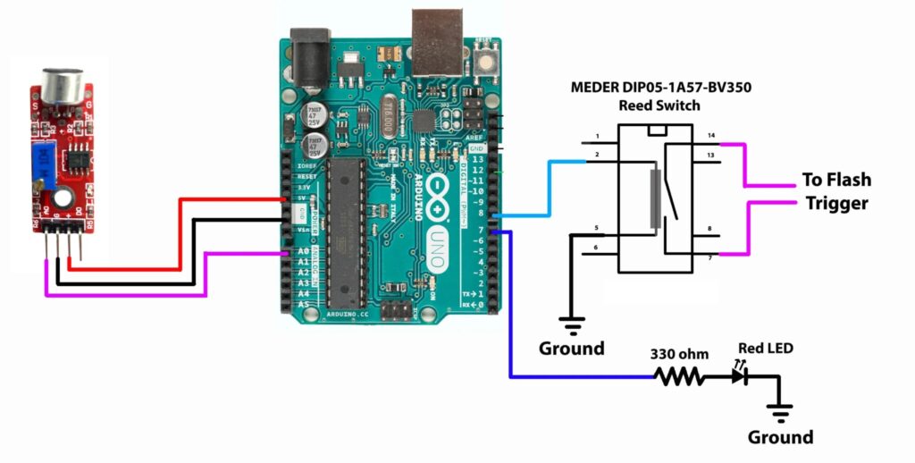
This device, based on an Arduino UNO Rev3 board, uses a microphone to listen for loud noises. If a noise exceeds a set threshold, the Arduino triggers the flash. An isolation circuit made with a Reed switch protects the Arduino from the high voltage of the flash. Reed switches are relatively slow, but they’re affordable. For better performance, an opto-isolator could be used instead.
To demonstrate this, students at Rochester Institute of Technology froze the action on some ballon pops and the results look great.
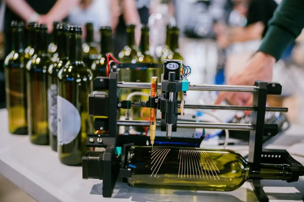
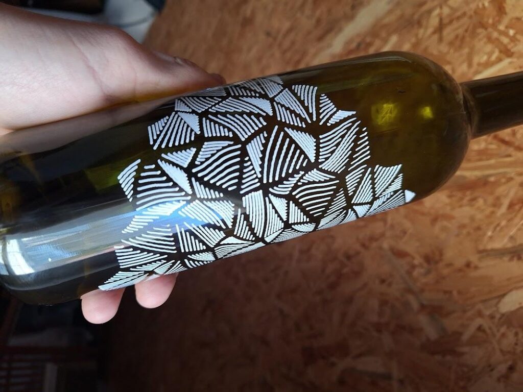
Manufacturers put a lot of effort into their packaging (there is an entire engineering discipline just for that) and some of it can be quite beautiful. But it usually still ends up in the landfill or, at best, in a recycling center. However, if you’re the type of person who can see the beauty in wine bottles, mason jars, and tin cans, then you can build the Bottle Plotter to transform trash into treasure.
This machine, developed by VGaman, is a CNC pen plotter with one linear axis swapped out for a rotary axis. That means that instead of plotting on a traditional XY plane, it plots around a cylinder. The “pen” can be anything that fits in the holder and the possibilities are almost endless. Paint markers seem especially well-suited to this kind of work, but there are certainly other options that may produce interesting results on some materials.
The Bottle Plotter is relatively affordable to build, as most of the parts are 3D-printable. The exceptions are fasteners, bearings, rods, and the electronic components. Those electronics include an Arduino UNO Rev3 board, a CNC shield, and stepper motors. VGaman’s design does include a Z axis (to move the pen closer to and further from the workpiece surface), so the machine requires three stepper motors.
The Arduino runs GRBL firmware and can accept any compatible G-code. The easiest way to generate that G-code is with a plugin for Inkscape, which will let users create artwork and then plot that all within one piece of software. Swap pens between toolpaths to make cool multicolor designs!
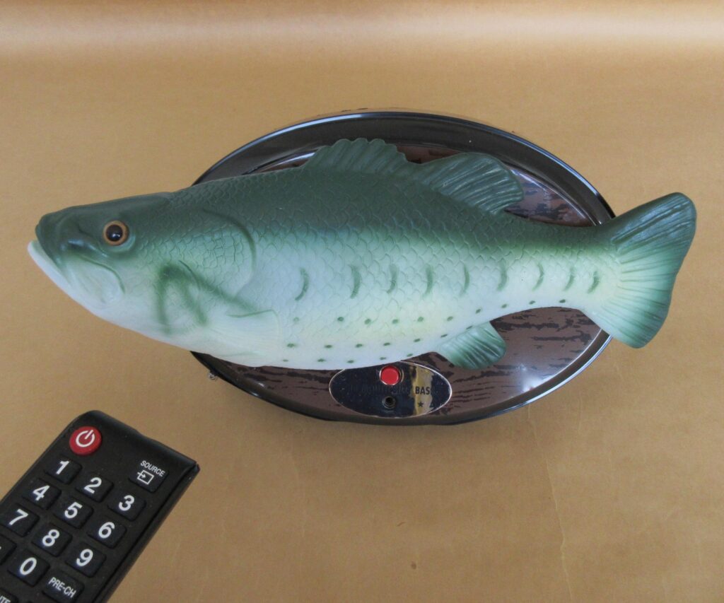
If you were unlucky enough to visit a big box retail store or goofy uncle’s home around the turn of the century, you would have undoubtedly come across a Big Mouth Billy Bass. That’s an animatronic fish that wiggles on a plaque while older, very licensable hit songs play. But while ol’ Billy was wildly popular at the time and spawned a whole new market segment, he wasn’t very sophisticated. Tony–K decided to address those cognitive shortcomings by giving Billy Bass an ‘arti-fish-al intelligence’ upgrade.
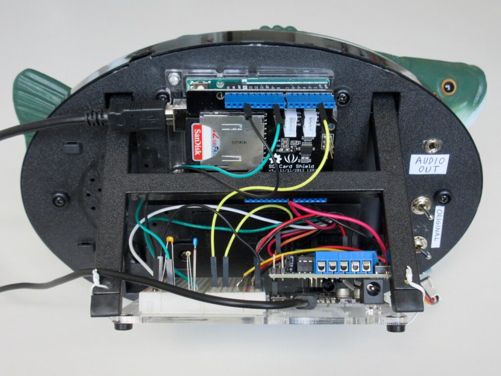
Internally, the original Big Mouth Billy Bass is quite simple. It has a single electric motor that drives the animatronic movement through a plastic mechanism, with a cheap sound chip that has Al Green’s “Take Me to the River” burned in. Tony–K’s modification gives the user fully control over everything, so they can program whatever behavior they like and use any audio. Using a standard infrared remote control, the user can activate those programmed sequences. If desired, Billy can be switched back to his normal routines.
Tony–K achieved that using two Arduino UNO Rev3 boards. One handles motor control, while the other plays audio. Tony–K chose to do that so he could use a motor driver shield with one Arduino and an SD card shield with the other. This takes advantage of the TMRpcm library, which makes it possible to play PCM and WAV files without a dedicated audio DAC (digital-to-analog converter). The audio quality won’t be stellar, but it is good enough for this purpose.
What to play all comes down to the builder’s ability to think up fish-related puns. If you can find a way to incorporate a Jimmy Buffett song, you’ll be golden!
Kinetic sand art tables are pretty hot right now, because they look really cool. They’re like zen gardens that rake themselves in intricate patterns. But most of the builds we’ve seen use a conventional cartesian CNC layout or polar layout. This table by Newsons Electronics takes a different approach inspired by spirograph drawing machines.
A spirograph is drawing template mechanism made up of at least two gears (and often several). By placing a pen in the hole, the user can draw a line that traces the path created by the gear movement. That path varies based on the gear parameters and can be extremely intricate. The geometric beauty is appealing and this table produces those patterns in sand.
Like other kinetic art tables, this draws in the sand by using a magnet to pull a ball bearing through the sand. In this case, that magnet attaches to a motor-driven spirograph mechanism underneath the table. One motor rotates the mechanism, while another motor actuates a rack-and-pinion that affects the path and ultimately the drawn pattern.
Those are both stepper motors and an Arduino UNO Rev3 board controls them through a stepper shield. The Arduino also controls the LED accent lighting, with potentiometer knobs to adjust brightness and the speed of animated transitions.
Newsons Electronics designed the table’s structure and frame to be made from stacked sheets of plywood cut out with a laser for precision, but it would be possible to make the parts with a CNC router or even a scroll saw. The result is a gorgeous piece of kinetic art.
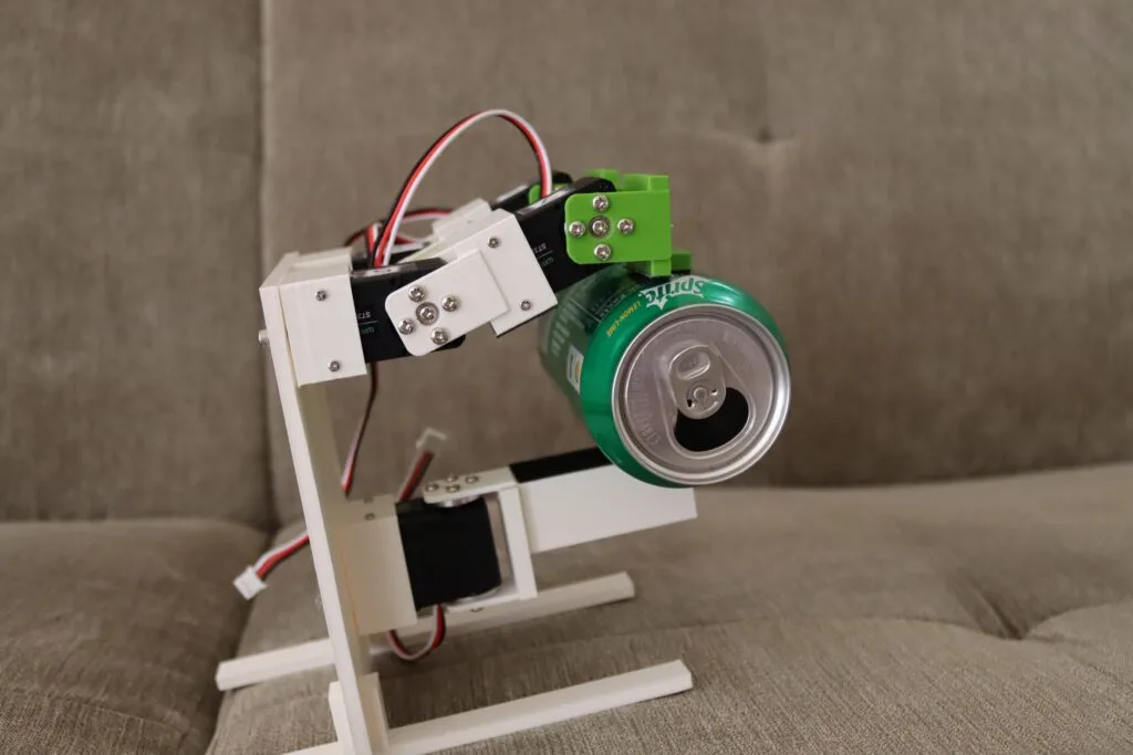
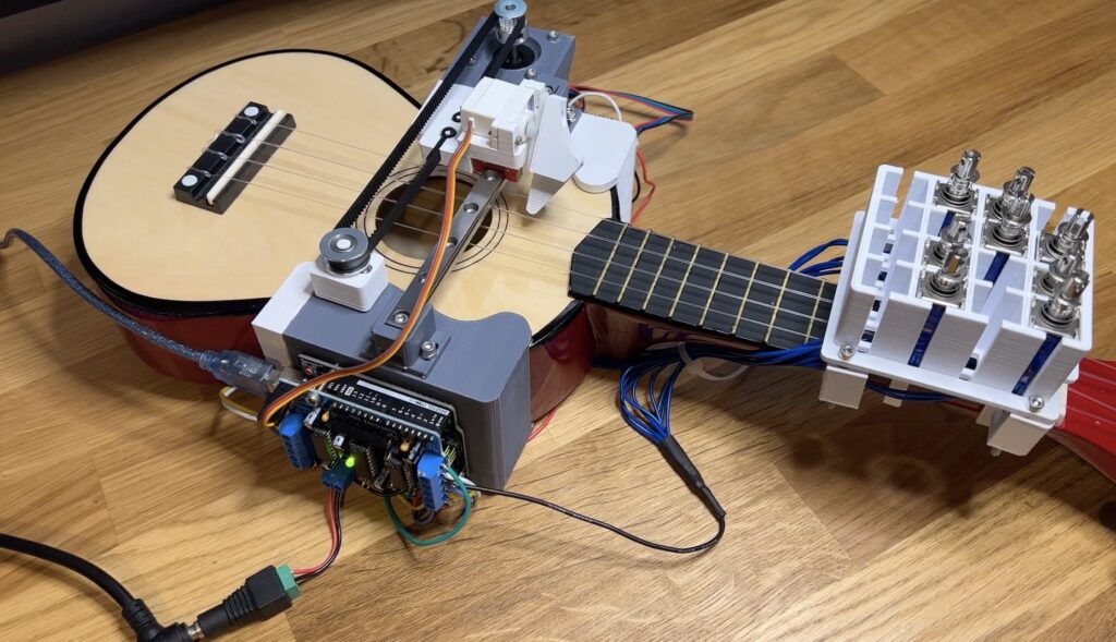
The ukulele has a bit of a reputation for being quaint, but it is a legitimate instrument like any other and that means it takes a lot of practice to play competently. Zeroshot is too busy building cool stuff to bother with all of that, so he put his skills to use constructing this robotic ukulele that plays itself.
Like a guitarist, a ukulelist can play a note by strumming multiple strings at once or by picking individual strings. More exotic techniques are also possible, but uncommon and outside the scope of this project. The key to Zeroshot’s design is the mechanism that can both pick and strum. It does so by using two actuators: a servo motor to lift and drop the pick, and a stepper to slide the pick back and forth perpendicular to the strings.
An Arduino UNO Rev3 board controls those motors through a HiLetgo L293D motor shield, with a TMC2208 driver module for the stepper. The Arduino can lower the pick and strum it across all of the strings, or it can move to a specific string and pluck just that one.
But it would be limited to only a handful of songs if it could only play open strings, so Zeroshot also needed to add hardware to hold the strings down on the fretboard. He chose solenoids for that job, held in a 3D-printed mount. With power coming from the motor shield, the Arduino can extend the solenoids to play any required notes.
Zeroshot designed the mount to accommodate up to 16 solenoids, for the first four frets across the four strings. When including open strings, that would give the robot up to 20 notes to work with. But a lot of songs only require a handful of solenoids, as Zeroshot demonstrated by performing Celine Dion’s “My Heart Will Go On.”
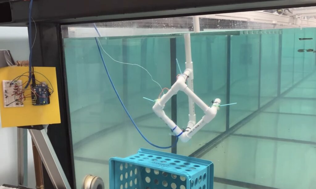
Who doesn’t want to explore underwater? To take a journey beneath the surface of a lake or even the ocean? But a remotely operated vehicle (ROV), which is the kind of robot you’d use for such an adventure, isn’t exactly the kind of thing you’ll find on the shelf at your local Walmart. You can, however, follow this guide from Ranuga Amarasinghe to build your own ROV for some aquatic fun.
Amarasinghe is a 16-year-old Sri Lankan student and this is actually the second iteration of his ROV design. As such, he’s dubbed it “ROV2” and it appears to be quite capable. All of its electronics sit safely within a 450mm length of sealed PVC tube. That mounts onto the aluminum extrusion frame structure that also hosts the six thrusters powered by drone-style brushless DC motors.
ROV2’s brain is an Arduino Mega 2560 board and it drives the BLDC motors through six electronic speed controllers (ESCs). It receives control commands from the surface via an umbilical. The operator holds a Flysky transmitter that sends radio signals to a receiver floating on the water. An Arduino UNO Rev3 reads those and then communicates the motor commands to the Mega through the tethered serial connection. That limits the maximum length of the tether to about 40 meters, which subsequently limits the maximum operating depth.
With the specified lithium battery pack, ROV2 can traverse the depths for 30-45 minutes. And when equipped with the 720p FPV camera, pilots can see and record all of the underwater action.
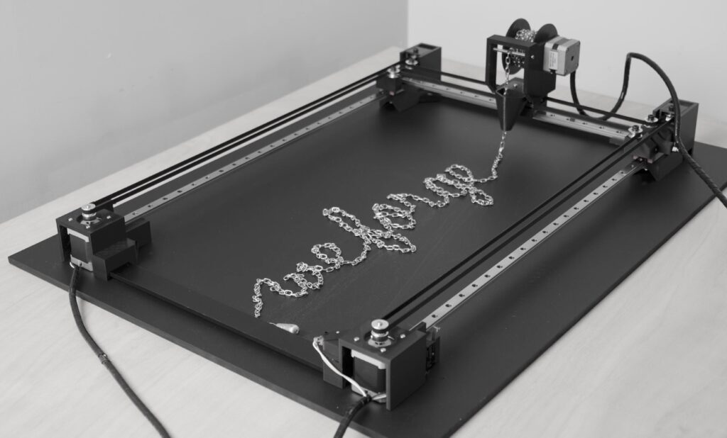
Art is very personal and we often consider the process of creation itself when evaluating the resulting piece. Does a sculpture have more artistic value when molded by human hands rather than a 3D printer? Most would say that it does. But what if the automation was, itself, part of the art? Yuichiro Katsumoto explored that idea with the “Renment (alpha)” chain art machine.
This is a bit like a large pen plotter, except that it “draws” with chains instead of ink. As the machine’s toolhead moves around the table following the paths of characters, a spool slowly drops steel chain into the form of those characters. After the machine finishes spelling out a word or phrase, it reels the chain back in and the process repeats.
In the published video demonstration, it writes out the phrase “we forge the chains we wear in life” coined by Charles Dickens.
The machine has three axes: the linear X and Y axes typical of a pen plotter, plus an additional rotary axis for the 3D-printed chain spool. Katsumoto based the design on DIY Machines Ltd’s coffee table kinetic sand art machine. An Arduino UNO Rev3 board controls the machine’s stepper motors through an Arduino CNC Shield V3.51, which is compatible with Grbl and can accept any g-code of that flavor.
Katsumoto created “Renment” with support from JSPS KAKENHI Grant Number JP20K12125 and displayed the piece at SIGGRAPH Art Galley ’24.
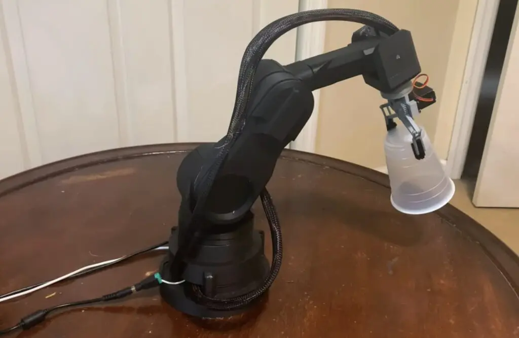
If you have an interest in robotics, then a robot arm is a great educational tool to start your journey. But professional robot arms are expensive and the DIY route is more informative anyway. That’s especially true if you take the time to design the arm yourself, as did Oliver Paff after he got himself a 3D printer and used his newfound fabrication capability to create this affordable 3D-printable robot arm.
Paff’s goal wasn’t to build the best robot arm in history. His goal was to learn the basics of robotics, including mechanical design, CAD, 3D printing, electronic design, and programming. This robot arm was perfect for that goal. It doesn’t have a high payload capacity or very good repeatability, but it was cheap to assemble and gave Paff a platform for experimentation and learning.
This is a 6DOF robot arm that Paff designed himself in Onshape. Almost all of the structural and mechanical parts were 3D-printed on an inexpensive Creality Ender 3.
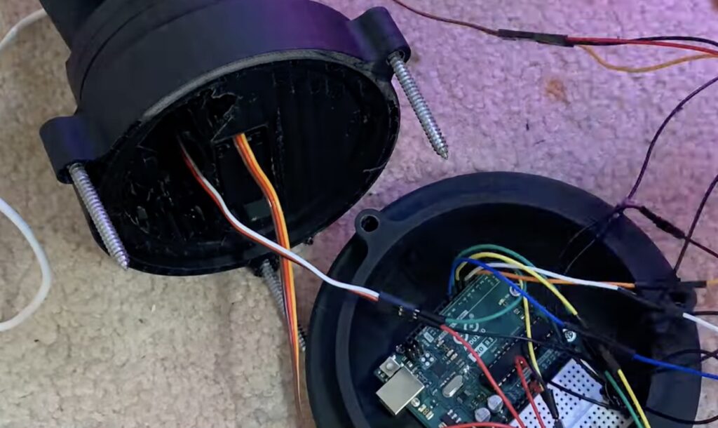
An Arduino UNO Rev3 board controls the servo motors that actuate the joints. Paff initially tried to drive those directly from the Arduino, but ran into a common issue: the Arduino’s pins cannot supply a lot of current. So Paff added a servo motor driver module, which solved that problem and gave the motors plenty of power. Paff also redesigned the gripper to be more versatile. And the code even incorporates inverse kinematics to make user control more intuitive.
In testing, this worked quite well and Paff has plans to continue improving the design over time and expand its capabilities. If you’re interested in constructing the current version, Paff was kind enough to upload his files.
Um dir ein optimales Erlebnis zu bieten, verwenden wir Technologien wie Cookies, um Geräteinformationen zu speichern und/oder darauf zuzugreifen. Wenn du diesen Technologien zustimmst, können wir Daten wie das Surfverhalten oder eindeutige IDs auf dieser Website verarbeiten. Wenn du deine Einwillligung nicht erteilst oder zurückziehst, können bestimmte Merkmale und Funktionen beeinträchtigt werden.
Funktional
Immer aktiv
Die technische Speicherung oder der Zugang ist unbedingt erforderlich für den rechtmäßigen Zweck, die Nutzung eines bestimmten Dienstes zu ermöglichen, der vom Teilnehmer oder Nutzer ausdrücklich gewünscht wird, oder für den alleinigen Zweck, die Übertragung einer Nachricht über ein elektronisches Kommunikationsnetz durchzuführen.
Vorlieben
Die technische Speicherung oder der Zugriff ist für den rechtmäßigen Zweck der Speicherung von Präferenzen erforderlich, die nicht vom Abonnenten oder Benutzer angefordert wurden.
Statistiken
Die technische Speicherung oder der Zugriff, der ausschließlich zu statistischen Zwecken erfolgt.Die technische Speicherung oder der Zugriff, der ausschließlich zu anonymen statistischen Zwecken verwendet wird. Ohne eine Vorladung, die freiwillige Zustimmung deines Internetdienstanbieters oder zusätzliche Aufzeichnungen von Dritten können die zu diesem Zweck gespeicherten oder abgerufenen Informationen allein in der Regel nicht dazu verwendet werden, dich zu identifizieren.
Marketing
Die technische Speicherung oder der Zugriff ist erforderlich, um Nutzerprofile zu erstellen, um Werbung zu versenden oder um den Nutzer auf einer Website oder über mehrere Websites hinweg zu ähnlichen Marketingzwecken zu verfolgen.