Schlagwort: #technology

  • An easy way to add a gear indicator for your stick shift

    An easy way to add a gear indicator for your stick shift

    Reading Time: 2 minutes

    The objective benefits may be almost nonexistent today, but there is still something satisfying about rowing through the gears in a car with a manual transmission. If that car was made in the past couple of decades, there is a good chance that it has an indicator on the dash to tell you what gear you’re in. But older cars usually don’t have an indicator, which is why you might want to follow Vaclav Krejci’s guide to add one.

    The great thing about this project is that it is easy to perform — even for beginners. Gearheads that don’t typically touch electronics can complete this build with some patience. Once done, it will display the current gear and a visual diagram on a small OLED screen, which the user can then mount anywhere in their car. 

    This works using an arrangement of four Hall effect sensors that detect the strength of the magnetic field coming from a permanent magnet attached to the gear shift lever. The principle is similar to triangulation, because the values detected by the four sensors can be used to calculate the position of the magnet. That isn’t very precise, but it doesn’t need to be for an application like this.

    The four Hall effect sensors mount onto a custom PCB. That connects to an Arduino UNO Rev3, which the user can tuck away inside of a center console. The Arduino performs the calculations, then updates the OLED screen with the results. Krejci even demonstrates how the user can simulate the entire circuit using WOKWI, which is very useful for ironing out kinks before building a hardware prototype. 

    [youtube https://www.youtube.com/watch?v=QixtxaAda18?feature=oembed&w=500&h=281]

    The post An easy way to add a gear indicator for your stick shift appeared first on Arduino Blog.

    Website: LINK

  • ED-HMI3020 Pi 5 touchscreen review

    ED-HMI3020 Pi 5 touchscreen review

    Reading Time: 2 minutes

    An upgrade over the HMI3010 models, the HMI3020 adds RS232 and RS485 interfaces, as well as 3.5mm headphone and mic jacks. The key addition, however, is an M.2 socket. To access it, you’ll need to unscrew Raspberry Pi 5 and the case from the rear of the unit, then you can use the M.2 slot inside to add an NVMe 2230, 2242, or 2260 SSD.

    Mounted on the rear, Raspberry Pi 5 has its main ports accessible through the rugged case

    Touch control

    Our unit’s microSD card had Raspberry Pi OS Bookworm pre-installed with the drivers for the ten-point touchscreen, which worked instantly upon bootup. As we’ve found with other Raspberry Pi touchscreens, there’s no right-click functionality by default and we also couldn’t double-click files to open them (so had to enable one-click opening in the File Manager). There was no on-screen keyboard available either, though we managed to get one running with a workaround from the Raspberry Pi forums.

    The EDI-HMI3020 also comes with an optional 8MP front-facing camera – a Camera Module V2 – for video conferencing and suchlike, making it a versatile touchscreen tablet.

    Verdict

    8/10

    A robust touchscreen panel with well-protected Raspberry Pi 5 mounted on the rear and the option to add an M.2 SSD

    Specs

    Features: 10.1-inch screen with ten-point touch input, Raspberry Pi with 4GB or 8GB RAM, optional front-facing camera

    Ports: 2 × USB 3.0, 2 × USB 2.0, 1 × USB-C power, 2 × micro-HDMi, Ethernet (with optional PoE), RS232 and RS485, M.2 SSD socket (internal)

    Dimensions: 258 × 172 × 39.6mm; 1000g

  • High school student builds his dream racing wheel

    High school student builds his dream racing wheel

    Reading Time: 2 minutes

    Racing “video games” can be incredibly realistic these days, with every facet of the car’s physics and their interaction with the asphalt programmed in. Those racing sims could provide a completely immersive experience — if the player wasn’t sitting on a motionless couch using a controller that doesn’t resemble a car’s steering wheel in the slightest. To rectify that issue, high school student Pranshu Agnihotri built his dream racing wheel.

    Agnihotri tackled this project for a senior project in his Principles of Engineering class at Irvington High School. Its purpose is to provide a more realistic interface for racing games and sims. It doesn’t have any force feedback capabilities, but it will work with any PC game thanks to the Arduino that lets the user easily rebind controls. Those can even emulate keyboard and mouse inputs for games that weren’t designed for use with steering wheels.

    The brain is an Arduino Leonardo, which Agnihotri chose for its Microchip ATmega32U4 microcontroller. That is configurable as a standard USB HID, so any computer will recognize its inputs without any special drivers or software. The steering wheel and electronics enclosure were 3D-printed in exactly the shape Agnihotri wanted. An M8 threaded shaft acts as the steering column. A potentiometer provides steering angle input, while limit switches detect when the player presses the paddle shifters. The Arduino reads those inputs, then sends out the corresponding gamepad, keyboard, or mouse commands via USB.

    [youtube https://www.youtube.com/watch?v=sIjAQyDc9xQ?feature=oembed&w=500&h=281]

    We have to assume that Agnihotri aced this assignment, and now he has an awesome steering wheel to race with. 

    The post High school student builds his dream racing wheel appeared first on Arduino Blog.

    Website: LINK

  • Arduino Days: Full schedule is online!

    Arduino Days: Full schedule is online!

    Reading Time: 2 minutes

    This year we have so many talks, presentations, and announcements we had to spread out over three days! Arduino Days 2024 will be held from March 21st to 23rd – giving us more time to celebrate our community with our yearly event: 100% online, free, and open to all.

    The full schedule is now available on the dedicated Arduino Days website: explore the program to find the topics that are the most inspiring or interesting to you, and turn on notifications for the three YouTube lives linked below. 

    Day #1: March 21st from 3:30 PM CET — Let’s Get to Business

    [youtube https://www.youtube.com/watch?v=x_hJ4-JPsag?feature=oembed&w=500&h=281]

    We start off with a day dedicated to innovative transformation for professionals. From Bob Martin (Wizard of Make / Senior Staff Engineer at Microchip) and Foundries.io CEO George Gray, to founder and CEO of Blues Ray Ozzie and Bosch general manager Marcellino Gemelli – you’ll hear from a variety of pros who are leveraging the open-source ecosystem to innovate their industry with flexible, reliable, out-of-the-box solutions.

    Day #2: March 22nd from 3:30 PM CET Makers in the Making

    [youtube https://www.youtube.com/watch?v=k9FsXG5thsA?feature=oembed&w=500&h=281]

    On the second day, the spotlight turns to the educators who embrace Arduino as a platform to teach STEM and engage students of all ages and skill levels. Discover how teachers can use Arduino’s Science Kit R3 to reveal the beauty of physics in Alan Bates’ talk, or find out how Alvik supports MicroPython beginners with project-based learning in Austin Gardner’s. And don’t miss new product presentations: we’re excited to introduce you to the upcoming PLC Starter Kit!

    Day #3: March 23rd from 3: 30 PM CET All About the Community

    [youtube https://www.youtube.com/watch?v=wSdFAJ3gcpM?feature=oembed&w=500&h=281]

    Last, but definitely not least, Saturday will be a huge celebration of makers’ diverse skills and passions! Join this third awesome session to hear about a variety of original projects presented by their own creators, and dive deep into topics ranging from accessibility (with inventor Danielle Boyer) to product quality testing. Don’t miss our partner talks – with STMicroelectronics, Analog Devices, and more – and keep an ear out for our latest major announcements, including one for the new product we’ve been working on with Silicon Labs.

    We hope you’ll join us to celebrate Arduino Days live on YouTube, and let us know what your favorite sessions are in the chat comments. 

    Don’t forget there will also be dozens of in-person independent events around the world: check out the Arduino Days website in a few days for the official map! 

    No matter how you decide to show your love for open source, we look forward to seeing you at Arduino Days!

    The post Arduino Days: Full schedule is online! appeared first on Arduino Blog.

    Website: LINK

  • DIY “Staccato” controller drives Tesla coils

    DIY “Staccato” controller drives Tesla coils

    Reading Time: 2 minutes

    The Tesla coil, patented by legendary inventor Nikola Tesla in 1891, is a kind of resonant transformer circuit capable of producing sparks of high-voltage alternating-current electricity. They don’t have many practical uses today beyond novelty, but they were commonly used in spark-gap radio transmitters in the early 20th century. The sparks generated by a Tesla coil would emit strong bursts of radio waves and operators could encode information through patterns of pulses, similar to a wired telegraph. But those sparks are difficult to control, which is why Mirko Pavleski designed this Arduino-based “staccato” controller for Tesla coils.

    The purpose of Pavleski’s device is to gain better control over a Tesla coil, with the goal of generating longer sparks with less power. It does so by providing very granular control over the length of each pulse, its intensity, and the interval between pulses. A Tesla coil requires a lot of voltage to create a spark, but very little current. That means that the total power needed to produce a spark is minimal and relatively safe to oversee with a microcontroller.

    In this case, Pavleski used an Arduino Nano to manage the circuit. A control panel lets the user adjust the parameters, then the Arduino does the rest. Power comes in from mains via a 12V transformer and the Arduino controls the current going from that to the Tesla coil with a standard triac, with a large capacitor providing some filtering. Almost everything else comes down to the Arduino’s programming, which ultimately determines the characteristics of the electricity supplied to the Tesla coil. Because that’s going through a triac, the Arduino can “dim” the voltage, as opposed to simply toggling it like a relay would.

    [youtube https://www.youtube.com/watch?v=JNNYee-Tons?feature=oembed&w=500&h=281]

    This will let Pavleski perform more in-depth experiments with Tesla coils.

    The post DIY “Staccato” controller drives Tesla coils appeared first on Arduino Blog.

    Website: LINK

  • GitHub Universe attendees treated to custom RP2040 Badgers

    GitHub Universe attendees treated to custom RP2040 Badgers

    Reading Time: 2 minutes

    Special custom gift

    GitHub’s Martin Woodward made a dedicated repo to help conference attendees learn how to hack their badges. Lo and behold, in it he confirms that the hackable conference badges are indeed a custom version of the Badger 2040 that Pimoroni made especially for GitHub.

    An RP2040 is running MicroPython which throws text up on a built-in 2.9-inch E Ink display. All five buttons dotted around the edge of the screen are user-configurable, and there’s also a Stemma QT expansion port so you can connect your own accessories, such as sensors. You can power the badge via its USB-C port, or use either a 2 × AAA battery pack or a standard 3.7V LiPo cell. It’s “extremely low power”, according to Martin, which is what you need when you’re wandering around a conference all day and don’t want to be tied to a power outlet.

    Open source ideas

    Custom PCB aside, the GitHub Universe Badger is electronically identical to the original Badger 2040. This means conference attendees can make use of all the open-source examples already out there, as people have shared cool things they’ve done with their Badger – the devices aren’t tied to a one-time use as a conference badge. Pre-loaded goodies on the GitHub Universe Badger include an eBook reader, to-do list, and image viewer.

    Want cool badges for your event?

    Martin’s GitHub repo pointed us towards Badge.team, an open-source community for people who want to create excellent badges for events. There are some magical designs on display in the gallery already. They’re also looking for volunteers to support the project, so join their Telegram group or Discord channel if you think you can help people make next-level event badges.

  • Autochef-9000 can cook an entire breakfast automatically

    Autochef-9000 can cook an entire breakfast automatically

    Reading Time: 2 minutes

    Fans off Wallace and Gromit will all remember two things about the franchise: the sort of creepy — but mostly delightful — stop-motion animation and Wallace’s Rube Goldberg-esque inventions. YouTuber Gregulations was inspired by Wallace’s Autochef breakfast-cooking contraption and decided to build his own robot to prepare morning meals.

    Gregulations wanted his Autochef-9000 to churn out traditional full British breakfasts consisted of buttered toast, eggs, beans, and sausage. That was an ambitious goal, because each of those foods requires several steps to prepare. Gregulations’ solution was to, essentially, create one large machine that contains several smaller CNC machines. Each one is distinct and tailored to suit a particular food. In total — if you add up all of the different sections — this is a 12-axis CNC machine.

    The Autochef-9000’s central controller is an Arduino Mega 2560 board. But even with the power and number of pins available, that wouldn’t have been able to handle everything. So it divvies out some tasks to Arduino UNO Rev3 boards.

    As you would expect, this takes quite a lot of heat to cook everything. That’s why the Autochef-9000 contains several electric heating elements, which the Arduinos control via relays.

    Users can order food using a touchscreen menu system or a smartphone interface. Autochef-9000 will then whir to life. It will open and heat a tin of beans, grab and heat a sausage, hard boil an egg, and toast and then butter bread fed from a magazine. Finally, it will deposit all of those items onto a plate.

    There is a lot going on inside of this machine and Gregulations breezes past a lot of the technical details, but it is a joy to see in action. And unlike Wallace’s inventions, this one hasn’t caused any serious disasters (yet).

    [youtube https://www.youtube.com/watch?v=LMoHLUd81P8?feature=oembed&w=500&h=281]

    The post Autochef-9000 can cook an entire breakfast automatically appeared first on Arduino Blog.

    Website: LINK

  • This new game engine runs Manic Miner on an Arduino UNO

    This new game engine runs Manic Miner on an Arduino UNO

    Reading Time: 2 minutes

    For owners of Sinclair ZX Spectrum computers in the ‘80s, few games were more desirable than Matthew Smith’s Manic Miner. It is very much a classic and has official and unofficial ports available for just about every console and computer released since. There was even a port made for Microsoft’s Zune MP3 player. And now you can play it on an Arduino UNO thanks to Scott Porter’s custom game engine and port.

    This isn’t the first time someone has done this, as James Bowman created a Manic Miner port for Gameduino a decade ago. But Porter’s project is a little different. His port runs on a custom engine on an Arduino UNO Rev3 that produces composite video output through a custom shield. That shield also contains a speaker driver circuit, buttons for control, and a port to connect an NES controller for a more comfortable gaming experience.

    Porter’s biggest challenge was generating video, as that requires very accurate timing. For that reason, he recommends using an official UNO and not generic boards that sometimes cut corners with resonators instead of crystals. 

    The game engine is impressive, with a fixed framerate of 50fps at 256×256 and up to nine sprites on screen. One of those sprites can have pixel-perfect collision detection with all of the others, which is ideal for a game like Manic Miner. But the video is monochrome and there do seem to be some glitches evident in the demonstration video. Regardless, this is very impressive and we’re excited to see what else Porter can achieve with his engine. 

    [youtube https://www.youtube.com/watch?v=dm_dUSeIqC4?feature=oembed&w=500&h=281]
    [youtube https://www.youtube.com/watch?v=5iUYeZ2Ppnk?feature=oembed&w=500&h=281]

    The post This new game engine runs Manic Miner on an Arduino UNO appeared first on Arduino Blog.

    Website: LINK

  • PicoZX Handheld

    PicoZX Handheld

    Reading Time: 2 minutes

    Peter Misenko (Bobricius to his friends on GitHub, and YouTube, is the brain behind the original design for PicoZX, and PicoZX Handheld – the Raspberry Pi Pico-based Spectrum emulator that inspired Ken.

    Peter’s short and snappy demo video explains the project, but Ken’s longer build video, goes into more detail on how he made his version.

    Components being soldered onto the PicoZX Board

    Reason number one why I personally would argue [are you sure you want to do this – Ed.] that PicoZX might be even better than the original ZX Spectrum: it exists in the now. Reason number two: it’s cuter because it’s smaller, meaning you can also use it as a handheld device and carry it around in your pocket. Reason number three: it’s built on Raspberry Pi Pico.

    Seeing as Sinclair was a pioneer of affordable home computing with the ZX Spectrum, it’s pretty cool to see a modern-day emulator running on a microcontroller which costs just $4/£4.

    How is it made?

    PicoZX is made up of several custom PCBs, but the Pico and most of the device’s parts are soldered onto one main board. There’s also a faceplate, which is largely cosmetic and holds everything in place nicely, and a backplate, which holds the battery and the charge controller. The other four PCBs frame the device around its edges, leaving openings for the microSD card and USB ports.

    Ken’s version of the PicoZX Handheld in eye-catching black

    A 2.8-inch IPS display soldered directly onto the main PCB is the screen for the device. Fifty 7mm tactile switches give the tiny QWERTY keyboard its clickety tactility. PicoZX can also be used with a joystick; Ken showcases an Atari 2600 joystick in his build video.

    How does it work?

    The Raspberry Pi Pico runs Fruit-Bat’s ZX Spectrum emulator and Jean-Marc Harvengt’s Multi-Computer Machine Emulator (M.CU.M.E). So not only do you have all of the original ZX Spectrum programs at your fingertips, but you can also emulate other devices – such as the Commodore 64, Atari 2600, and ColecoVision – all in one compact handheld device. You’ll have 1980s nostalgia coming out of your ears after a couple of hours with this thing.

    Remembering Clive Sinclair

    I’d wager you’re an admirer of Sir Clive Sinclair, the inventor of the ZX Spectrum, who died in 2021. Raspberry Pi co-founder Liz Upton wrote a short but sweet note on the day we heard the news, and the comments section quickly filled with stories from people who had been inspired by his work. Have a look if you’d like to take a scroll down memory lane.

  • This animatronic CatNap is predictably creepy

    This animatronic CatNap is predictably creepy

    Reading Time: 2 minutes

    Poppy Playtime is an interesting horror video game — or rather, an episodic series of games — that puts players into the eerie toy factory of fictional company Playtime Co., where they find that the company’s characters are alive and quite aggressive. A big part of the game’s appeal is the creepy character design, with the eponymous Poppy being just one example. But they’re all scary, as Jaimie and Jay of the Wicked Makers proved when they built this life-sized CatNap animatronic.

    The Wicked Makers aren’t strangers to this game, as they previously built an eight-foot-tall Huggy Wuggy. Their CatNap animatronic isn’t quite as tall, but it is still huge. And it is a faithful recreation of the monster seen in-game. It can move its head side-to-side, and its body sort of sways like a real, breathing creature’s would. It even breathes glowing red fog to represent the in-game sleeping gas formulated for children.

    As usual, that vast majority of the work here went into constructing the animatronic’s skeleton, body, and head. It is a masterful mishmash of PVC pipe, wire, foam, clay, and fabric. But the real magic comes from the movement, which is possible thanks to the use of an Arduino UNO Rev3. That controls the torso’s wiper motor via a relay, the servo motor that moves the head, the LEDs for the eyes and smoke, and the smoke machine.

    To simplify the animations, the Wicked Makers turned to Bottango software. That’s free and made specifically for controlling animatronics. It makes programming and uploading animations easy, so the Wicked Makers can alter CatNap’s behavior whenever they want.

    The result is just as terrifying as it is impressive.

    [youtube https://www.youtube.com/watch?v=Fh6mimCibhQ?feature=oembed&w=500&h=281]

    The post This animatronic CatNap is predictably creepy appeared first on Arduino Blog.

    Website: LINK

  • Getting more realistic camera movements in VR with an Arduino

    Getting more realistic camera movements in VR with an Arduino

    Reading Time: 2 minutes

    In virtual reality, anything is possible, yet being able to accurately model things from the real-world in a digital space remains a huge challenge due to the lack of weight/feedback that would otherwise be present in physical objects. Inspired by working with digital cameras and the inherit imperfection they bring to their videos, Bas van Seeters has developed a rig that translates the feeling of a camera into VR with only a few components.

    The project began as a salvaged Panasonic MS70 VHS camcorder thanks to its spacious interior and easily adjustable wiring. An Arduino UNO Rev3 was then connected to the camera’s start/stop recording button as well as an indicator light and a potentiometer for changing the in-game focus. The UNO is responsible for reading the inputs and writing the data to USB serial so that a Unity plugin can apply the correct effects. Van Seeters even included a two-position switch for selecting between wide and telescopic fields of view.

    With the Arduino now sending data, the last step involved creating a virtual camcorder object in Unity and making it follow the movement of a controller in 3D space, thus allowing the player to track things in-game and capture videos. More details on the project can be found in van Seeters’ write-up here and in the video below!

    [youtube https://www.youtube.com/watch?v=vt5l4E0LUpg?feature=oembed&w=500&h=281]

    The post Getting more realistic camera movements in VR with an Arduino appeared first on Arduino Blog.

    Website: LINK

  • Argon ONE V3 M.2 NVME case review

    Argon ONE V3 M.2 NVME case review

    Reading Time: 4 minutes

    This month we have the hotly anticipated Argon ONE V3 M.2 NVMe PCIe Case. Hopes are high for this one and we can tell you it hits home runs all the way. Redesigned for Raspberry Pi 5 this board combines the features of the Argon ONE V2 with the – previously separate – M.2 Expansion Board add-on to create an all-in-one computer case with super-fast, and super-large, storage that also cleverly uses passive cooling and heatsinks to keep everything running. This is the one we have been waiting for.

    Underneath Argon ONE V3 is a removable thermal heatsink to fit the M.2 NVMe drive. Here we can also see the power button, full-sized HDMI slot, 3.5mm audio jack and Raspberry Pi 5 ports

    All together now

    The Argon ONE is Argon40’s flagship case, containing a daughterboard for Raspberry Pi that adds additional features such as full-sized HDMI sockets and an infrared (IR) receiver.

    On the base of Argon ONE V3 is a removable cover that provides access to the M.2 NVMe socket. Here you can insert any M.2 NVMe with M-Key up to 2280 size. The flap is marked “THERML” which nods to its aluminium heatsink and a long strip of thermal pad is included to transfer the heat out into the case.

    Two more silicon pads are included to connect Raspberry Pi’s CPU and PMIC (Power Management Integrated Circuit) to the case.

    Alongside this impressive passive cooling is a redesigned 30mm fan and blower. This is repositioned at an angle to be “more efficient and quiet”, and we found it unobtrusive even when stress testing.

    Argon ONE V3 now sports Raspberry Pi’s RP2040 microcontroller to control various functions like fan speed and power management (via jumper pins on the daughter board). The power button is less of a novelty now that Raspberry Pi 5 itself features one. However, the presence of a 3.5mm audio jack will be a welcome addition for audio buffs now that it has been removed from Raspberry Pi 5’s main board.

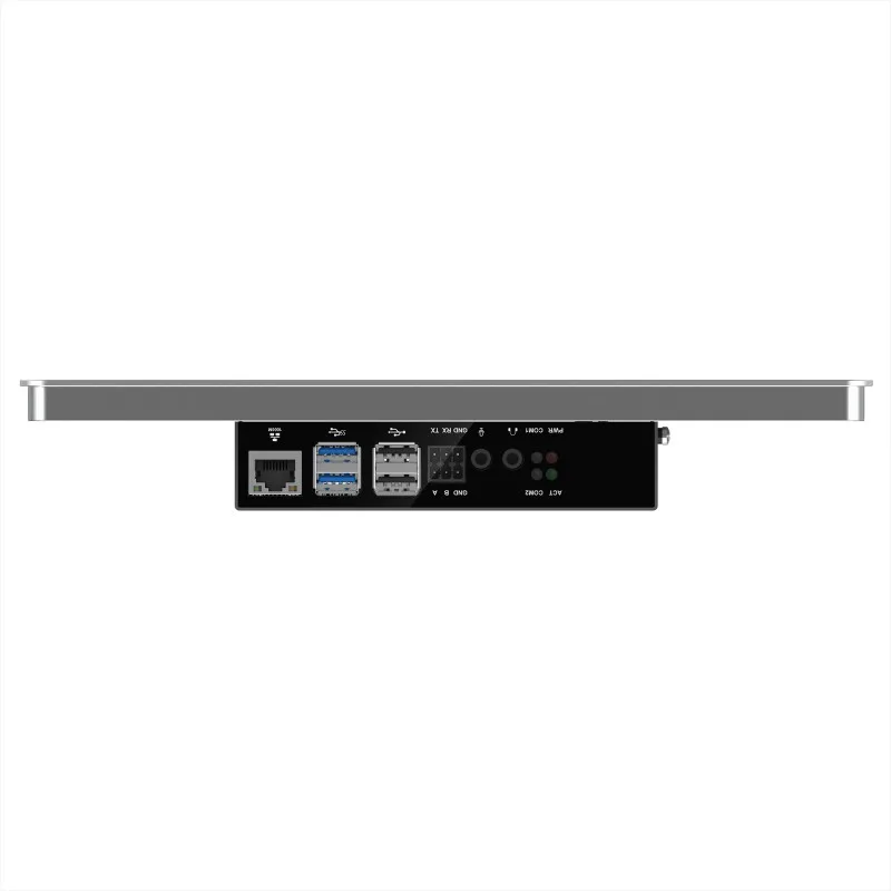
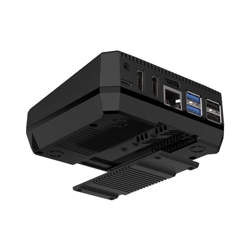
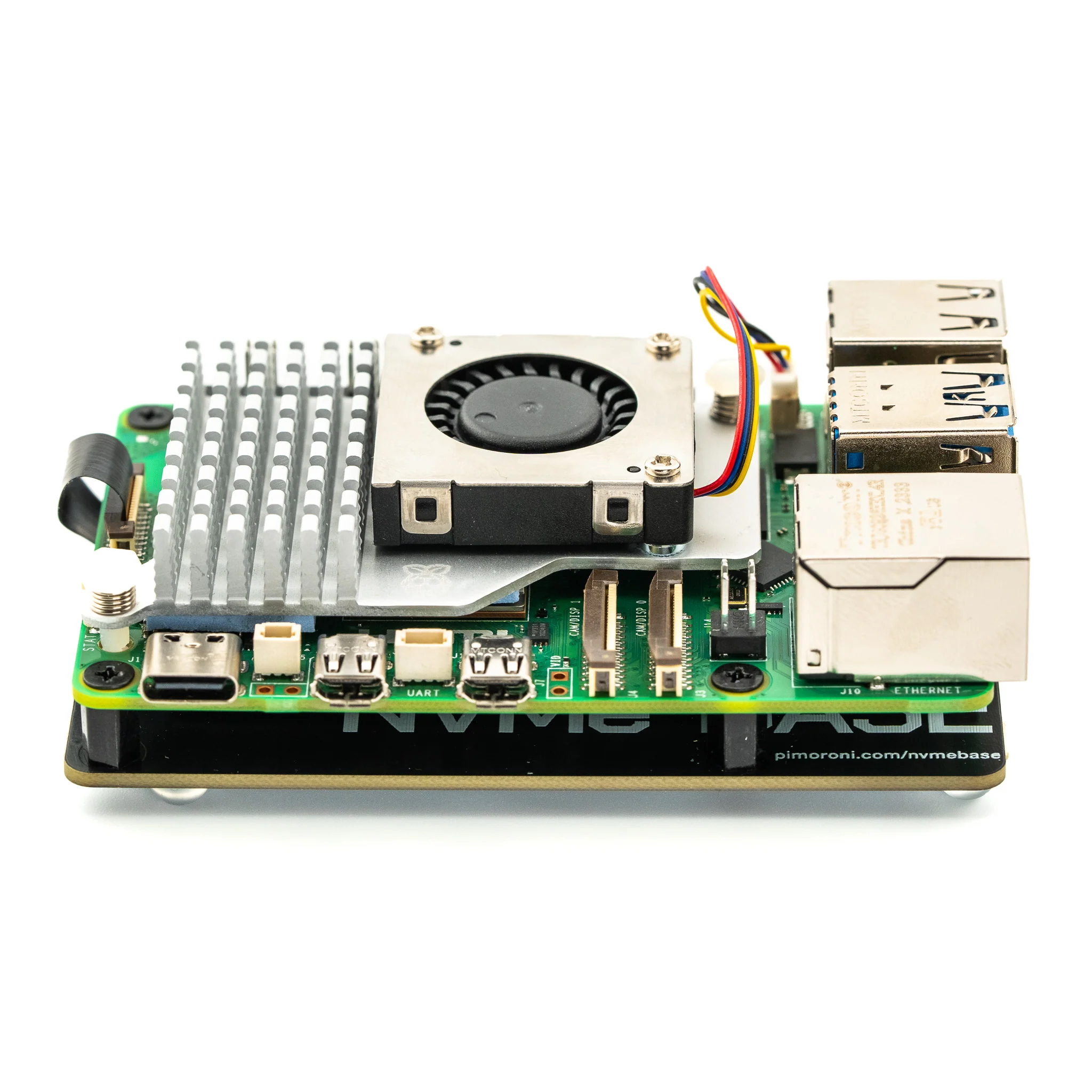
    One advantage over the Argon ONE V2 board is that the M.2 NVMe now connects directly to the PCIe socket on Raspberry Pi 5. This leaves all four USB-A sockets available.

    A removable magnetic flap on top of the case provides access to repositioned GPIO pins alongside a handy pinout guide.

    Assembly and testing

    Putting together the Argon ONE V3 was a relatively painless process thanks to the included assembly instructions. Raspberry Pi 5 is connected to the HDMI daughterboard, and the PCIE cable is used to connect the bottom half of the case to Raspberry Pi 5. Then the whole thing is screwed together. Finally, the M.2 NVMe storage is connected to the underside making it possible to upgrade the drive without opening the whole case.

    As with previous Argon ONE cases, the microSD card is hidden away and can’t be used without opening up the case. This is less problematic these days as a USB thumb drive flashed with Raspberry Pi OS can be used to run Imager and flash the storage drive. Attach an Ethernet cable and you can also use Network Install with Raspberry Pi 5.

    Speed-testing of the NVMe drive tells you much more about the quality of your drive than the case itself. We used a 500GB WD Blue storage stick and measured the speed using Raspberry Pi OS’s built-in Raspberry Pi Diagnostics tool to test performance. It returned a sequential write speed 789590 KB/sec (790 MB/s) almost 80 times faster than the recommended pass speed for a microSD card. It’s fast.

    The heat test is also interesting. We used stress –cpu 4 and measured the output with the script found here for 15 minutes.

    Raspberry Pi 5 inside the Argon ONE V3 case idles at around 54°c (down from the 65°c baseline of an uncooled Raspberry Pi 5 without a heatsink). We found the fan kicked in at the 60°c mark after five minutes and kept the Raspberry Pi 5 hovering around 61°c for another 10 minutes. At no point did Raspberry Pi OS reach the 80°c mark where performance throttling begins. It compared favourably to a Raspberry Pi 5 and an official Active Cooler unit.

    Put it to use

    One optional extra we should mention is an internal Argon ONE BLSTR DAC audio board upgrade, which will be sold separately. Alongside the 3.5mm jack this will make Argon ONE V3 ideal for audio fans. We didn’t have one for testing and can’t see it on the Argon40 website just yet, so hopefully that will come down the line.

    All of this transforms Raspberry Pi 5 from a hackable board to a desktop computer. A role our favourite computer is increasingly fulfilling with aplomb. The built-in infrared connection, large storage, and full-sized HDMI connection also ensure Argon ONE V3 becomes the perfect media player or home games console. This case is highly recommended.

    Verdict

    10/10

    An excellent case that sees a lot of Argon’s ideas reach fruition. Turn your Raspberry Pi 5 into a smart desktop computer, media player, games console or DAC audio player.

    Specs

    Components: Argon ONE Pi 5 V3 case, M.2 NVME carrier board, Video/Audio PCB extender (daughterboard), GPIO & Fan board, RP2040-based microcontroller

    Input/output: Adjustable M.2 NVME with M-Key up to 2280 size, 2 × standard (type A) HDMI ports, Ethernet, 4 × USB-A ports, USB-C power port, 3.5mm audio jack

    Cooling: Aluminium alloy case for passive cooling, blower type PWM programmable 30mm fan

  • Build yourself this simple app-controlled robot dog

    Build yourself this simple app-controlled robot dog

    Reading Time: 2 minutes

    If you have an interest in robotics, it can be really difficult to know where to start. There are so many designs and kits out there that it becomes overwhelming. But it is best to start with the basics and then expand from there after you learn the ropes. One way to do that is by building MertArduino’s adorable app-controlled robot dog.

    This is a little more complex than a typical line-following rover kit, but it is still approachable for beginners. It uses eight inexpensive MG90S hobby servo motors to walk on four legs, plus one more servo to rotate the head. The tutorial explains how to create a smartphone app for controlling the robot and there is an ultrasonic sensor hidden in the dog’s eyes to help it detect obstacles. 

    To construct this robot, you will first need to 3D print the body, legs, and head. Those parts are small enough to print on almost any model of 3D printer. You’ll then need the custom PCB, onto which all of the electronic components attach. You can order that from any PCB fabrication service. Using basic through-hole soldering techniques, you can populate that PCB with an Arduino Nano board, an HC-05 Bluetooth module (for communication with a smartphone), and various miscellaneous components like resistors and a voltage regulator. Power comes from a pair of 18650 lithium battery cells.

    After assembly, you can begin controlling the robot using the provided app. Or you can follow the instructions to make your own app with the help of MIT’s handy block-based Scratch programming tool.

    [youtube https://www.youtube.com/watch?v=NlUgbXlzpAw?feature=oembed&w=500&h=281]

    If you want to dip your toes into the world of robotics, this seems to be a fun way to do it.

    The post Build yourself this simple app-controlled robot dog appeared first on Arduino Blog.

    Website: LINK

  • SNES XL

    SNES XL

    Reading Time: 2 minutes

    Button management

    Every button on SNES XL controller has its own custom PCB, created using PCBWay an online service for producing PCB prototypes. Each board is shown fully working by Arnov on YouTube. Tactile switches on the custom boards are positioned just below the 3D-printed buttons, such that pressing a button toggles its switch. Each of the switches is wired up to a pin on a XIAO SAMD21 development board from Seeed Studio (see Figure 1). When SNES XL is connected to a computer (in this case Raspberry Pi 4), the Seeed XIAO appears as a gaming controller icon and can be selected for gameplay.

    Figure 1: The buttons are switches wired up to a pin on a Seeed XIAO SAMD21 board

    Too big to print or hold

    Arnov designed the controller housing in Fusion360. It had to be 3D printed in three separate parts due to its size, before being superglued together. More videos and images can be found on Arnov’s Instructables.

    Retro game emulation here comes courtesy of Recalbox. Power Pi, a Raspberry Pi dock/enclosure with an integrated lithium cell battery pack that Arnov also designed, provides power.

    Inside the giant 3D-printed case

    Arnov has to set the controller flat on the table to play games, because it’s too big to hold comfortably. Our favourite Raspberry Pi builds are the ones that are so absurd they turn out to be unusable for their originally intended purpose. The BFG would have no problem, but we’re still not sure if he’s real or not. We’ve let Nessie and Bigfoot go, but we’re hanging onto our oversized childhood friend.

    Gamer geek

    Arnov has graced us with his Raspberry Pi-powered gaming kit twice before. The first time was with SANDWICH DOT IO, an all-in-one desktop gaming system based around Raspberry Pi 3B+ and featuring on-board power as well as a dedicated cooling layer.

    The SNES XL is fully working (although hard to hold). Here, Arnov is using it to play a game of Doom!

    PALPi, a handheld games console with a retro aesthetic that’s powered by Raspberry Pi Zero W, is another of Arnov’s creations. Let’s start taking bets on what he builds next. We’re thinking he might go to the other end of the size spectrum and come up with something miniature. Maybe a teeny, tiny, thimble-sized Wii controller for dainty indoor tennis and golf.

  • A single stepper motor drives this mechanical seven-segment display clock

    A single stepper motor drives this mechanical seven-segment display clock

    Reading Time: 2 minutes

    It is amazing how much technological progress humanity has achieved over the past few centuries. But while our capability with electronics has shot ahead, it seems that we’ve almost regressed when it comes to mechanical and electromechanical design. Watches and clocks are great examples of this, as pre-digital craftsmen were capable of astonishing feats that are still impressive today. But some people are keeping those traditions alive, as evidenced by this mechanical seven-segment display clock driven by a single stepper motor.

    This clock is truly a work of art. It shows the time across six digits, each of which is a seven-segment display. But those aren’t segments lit by LEDs, they’re physical pieces of plastic. A complex series of gears flips them in and out in the appropriate sequence to display the numeric characters. That is very impressive when you consider that the segments don’t actuate in an order that correlates with the numerical value — the number 4 isn’t simply turning “on” one more segment than the number 3. But even so, the clock progresses through the numbers in order.

    That’s only possible because of the genius mechanical design of the clock. Further increasing the wonder is the fact that the clock and all of its parts were 3D-printed — no precision machining necessary. An Arduino Nano board controls the stepper motor that drives the whole series of gears. That ensures that the motor turns at a constant rate, which is required to keep accurate time.

    [youtube https://www.youtube.com/watch?v=TmxXhfyIY5g?feature=oembed&w=500&h=281]

    The post A single stepper motor drives this mechanical seven-segment display clock appeared first on Arduino Blog.

    Website: LINK

  • This kinetic light installation illuminates the Finnish snow

    This kinetic light installation illuminates the Finnish snow

    Reading Time: 2 minutes

    If you’re ever driving through rural Finland about an hour south of Jyväskylä, you might come across the Haihatus art center. That includes KITA, “the house of kinetic arts.” You’ll recognize it right away by its bold swaths of vibrant paint. And if you come by at night, you’ll see the snow illuminated in dancing colors by a kinetic art installation built by Niklas Roy and Kati Hyyppä.

    Because the building is unheated and can reach temperatures as low as -30°C (-22°F), KITA remains closed through the winter. Roy and Hyyppä approached this project with the goal of turning the building itself into a kinetic art piece for people to enjoy through the cold months. To achieve that, they lit the windows and added movement. Lights inside the building move along tracks and motors pull them with spools of twine. An Arduino Nano development board controls the motors through H-bridge drivers. Various reflectors and filters alter the lights as they move.

    To make that even more dynamic, they animated the illumination and introduced sound. A control box built into an old tool case contains another Arduino Nano that can switch the lights through relays. That Arduino also generates sounds and melodies from algorithms based on random inputs, but synced to the lights. 

    This project came with unique challenges related to the weather, as many electronic components act unpredictably at these extreme temperatures. But the installation worked well enough to unveil on New Year’s Eve 2023, when the people living in the town of Joutsa got to enjoy the dazzling inauguration.

    The post This kinetic light installation illuminates the Finnish snow appeared first on Arduino Blog.

    Website: LINK

  • Mac Mini KVMac16

    Mac Mini KVMac16

    Reading Time: 3 minutes

    The right tools

    Ivan values Raspberry P’s modularity which allows him to create unique devices and has previously used various models including Compute Module 4 in his Compute Blade, an energy-efficient alternative to a rack-mounted server. He praises the “relatively cheap minicomputer with a huge community, which greatly lowers the threshold of entry and increases trust”.

    For the Mac Mini KVMac16 project – Ivan describes it as “a console for 16 Mac minis on a shelf that occupies a 6U space in a server rack” – Raspberry Pi is used as a KVM (kernel-based virtual machine) while “the PiKVM HAT is used for video capture and keyboard/mouse command transfer”. Ivan chose Raspberry Pi because it both supports the components and offers long-term software support. He says: “Raspberry Pi 4 with 4GB is easily sufficient for the task”.

    KVMac16 helps get an offline Mac mini back up and running should an update or other issue cause it to be out of action

    As Ivan’s blog explains, should a Mac go down due to a failed update or any another reason, the only way to reboot it is to physically press its power button. This is not something that can be done remotely, and is the issue his KVMac device addresses. “To provide full control, with the ability to completely reinstall the OS, you need to press the power button and there are no other options.” Ivan has created the optimal workaround: a Servo HAT and self-written Python scripts control the servos used to physically push buttons on the Mac mini. He also uses RS232 to control a regular KVM switch from the user interface between a Raspberry Pi PiKVM HAT and 16 Mac minis, through which he can connect to any of them.

    Third time’s a dream

    As Ivan details on his Uplab blog, creating the KVM Mac Mini project involved three different versions, with improvements each time focusing on ease of installation and overall reliability. PiKVM is at the heart of the project, and provides a basic user interface, “but the ability to physically push buttons, and the 16 Mac mini install stand itself, are designed by me from scratch [as were the] custom scripts and UI modifications to give the user full control”.

    Ivan’s “perfect shelf’ for his Mac mini project allows air to circulate while being very robust

    Many of the challenges were because the project uses servos and levers to push buttons on the Mac minis, which need to work with maximum reliability. He started the project from scratch three times and counsels other would-be makers that if you find your project moving in the wrong direction, stop, reappraise and “have the strength to start over from scratch”. Ivan did this twice here, and says it strengthened his project as well as validating the potential for both a four-Mac mini model and a potential CI/CD one (Continuous Integration Continuous Deployment).

    It is just as well that Raspberry Pi proved a good option. Ivan says there are “simply no alternatives. This project was only possible thanks to Raspberry Pi and PiKVM.

  • Controlling 3.6kW of solar EV charging with an Arduino GIGA R1 WiFi

    Controlling 3.6kW of solar EV charging with an Arduino GIGA R1 WiFi

    Reading Time: 2 minutes

    The EV (electric vehicle) versus ICE (internal combustion engine) debate is more complicated that it may seem, but one fact is quite simple: it is much easier to generate electricity at home than it is to refine fossil fuels. This means that it is possible power a vehicle for free after the initial investment. But doing so takes quite a lot of hardware, which is why Shawn Murphy developed this charging system controlled by an Arduino GIGA R1 WiFi.

    Murphy owns a Ford Lightning electric pickup truck, which is inefficient by EV standards thanks to its weight. But even at just two miles per kWh of electricity, he estimates that he can break even on the cost of his solar charging system within four to five years. After that, the electricity to power the Ford will, essentially, be free. Any excess energy can power his home or feed back into the grid.

    Just powering the truck alone will require a lot of electricity, so Murphy acquired 10 used 360-watt solar panels. Those feed to a battery backup array, which supplies power to the Ford charging station. 

    To maximize efficiency, Murphy wants the solar panels to pivot on one axis to follow the sun. He estimates that will increase their output by 20-25% throughout the day, which is a significant amount of energy with a solar panel array this large. An Arduino GIGA R1 WiFi board controls the tilt of the panels via linear actuators. Murphy originally used “dumb” actuators, but is switching to “smart” models from Progressive Automations that include positional feedback through Hall effect sensors.

    A GIGA Display Shield gives Murphy access to an interface, which he can also access through the Arduino Cloud. In addition to controlling the linear actuators, the Arduino monitors power generation and consumption.

    This is still a work in progress as Murphy continues to make improvements, but he’s well on his way to “free” energy for his truck.

    The post Controlling 3.6kW of solar EV charging with an Arduino GIGA R1 WiFi appeared first on Arduino Blog.

    Website: LINK

  • This Arduino GIGA R1 WiFi project turns a coffee maker into a more accessible appliance

    This Arduino GIGA R1 WiFi project turns a coffee maker into a more accessible appliance

    Reading Time: 2 minutes

    While many of the things we interact with every day have become more usable by people with disabilities, the kitchen remains as one important area of our lives that still lacks many accessibility features. One of these commonplace appliances is the coffee maker and its array of small buttons or even a touchscreen that can be hard to see/touch. Orlie on Instructables has developed a set of wireless buttons and an accompanying receiver that translate simple actions into an easy, end-to-end brewing experience.

    Each button started as a custom 3D-printed shell with compartments for a AA battery holder, large arcade button, and the perfboard that also contained the ESP8266 microcontroller. In this system, the ESP8266 communicates with the Arduino GIGA R1 WiFi board via Wi-Fi and an MQTT message broker running on a host PC. This enables each button to be assigned a unique message that dictates the desired task to be performed.

    At the coffee maker, the GIGA R1 WiFi was wired into a pair of ULN2003 stepper motor driver modules that move a gantry across a set of linear rails and eventually push the corresponding buttons once the correct position has been reached. Ultimately, this allows for those with less mobility and/or dexterity to select what they want from anywhere in the house — all over Wi-Fi.

    To see how this project was built in greater detail, you can read Orlie’s write-up here on Instructables.

    The post This Arduino GIGA R1 WiFi project turns a coffee maker into a more accessible appliance appeared first on Arduino Blog.

    Website: LINK

  • NVMe Base review

    NVMe Base review

    Reading Time: 3 minutes

    Before attaching the NVMe Base to the underside of Raspberry Pi 5 using the supplied standoff kit – demonstrated in Pimoroni’s installation video – you’ll want to insert your NVMe SSD stick into the Base’s M.2 key slot. The board is long enough to accommodate 2280 size SSDs, and has mounting holes for this plus 2230, 2242, and 2260 drives – so you can secure it with a bolt and nut.

    Securing the Base

    The next step is to attach M2.5 standoffs to the top of the Base using the four mounting holes. The kit helpfully includes both short and long bolts – the latter are useful if you want to securely mount another HAT on top of Raspberry Pi 5.

    The NVMe Base comes with a standoffs kit, flat flexible PCIe cable, and four rubber feet

    Connecting the Base’s PCIe slot with the one on Raspberry Pi 5 is done using a small, flat S-shaped cable that flexes and has labels to help you orient it correctly – the end for the Base is slightly wider, at 18 pins. It’s easier to connect Raspberry Pi 5’s PCIe slot first, then the Base’s, due to the latter’s less fiddly flip tab. You can then fold the flexible cable over so the Base is underneath Raspberry Pi 5 to form a sandwich, before using a small screwdriver and bolts to secure it. The only downside is that the extra height means it won’t fit in a standard case.

    With the hardware installed, you’re ready to start using your SSD… that is, once you’ve checked that your system is up to date and you have the latest bootloader version selected in raspi-config: Advanced Options > Bootloader Version > Latest, then select ‘No’ and reboot. The drive should then appear in the /media directory, and be shown by the lsblk command. If not, make sure it is formatted (you can use Raspberry Pi Imager).

    Drive compatibility

    While the majority of NVMe M.2 drives should work fine, Pimoroni’s product page notes that a few models have quirks or have proved troublesome. The safest option is to choose a tested model listed there, or purchase the NVMe Base bundled with a compatible 250GB or 500GB SSD.

    The slimline NVMe Base fits snugly under Raspberry Pi 5, secured by bolts and standoffs

    Raspberry Pi 5 officially only supports the Gen 2.0 version of PCIe, but adding an extra line to /boot/config.txt will force Gen 3.0 for extra speed. In our tests, using the dd command, we achieved a write speed of 514MB/s and a read speed of 858MB/s. While far from our SSD’s maximum (due to only using one of its PCIe lanes), it’s still many times faster than microSD (typically around 30MB/s write, 90MB/s read), and also better than an SSD connected via speed-limiting USB. Check out Pimoroni’s own tests on various SSDs at.

    You’ll want to make Raspberry Pi 5 boot from the SSD instead of the microSD card. This is easily achieved by writing the OS to it with Raspberry Pi Imager and then selecting Advanced Options > Boot Order > NVMe in raspi-config. For our drive, this cut around four seconds from the average boot time. We also noticed that some apps, such as Chromium, seemed a little snappier.

    Verdict

    9/10

    A slimline adapter that sits neatly under Raspberry Pi 5 and enables fast PCIe read/write speeds with a suitable SSD

  • Motion control interface facilitates robot operation for those with paralysis

    Motion control interface facilitates robot operation for those with paralysis

    Reading Time: 2 minutes

    Henry Evans suffered a brain-stem stroke 20 years ago that left him paralyzed with quadriplegia. He can move his head, but other than a small amount of movement in his left thumb, he can’t control the rest of his body. To help Evans live a more independent life, researchers from Carnegie Mellon University’s School of Computer Science developed a motion control interface that lets him operate a mobile robot.

    The robot is a Stretch model from Hello Robot, which can navigate a home on its mobile base, interact with objects using its arm and gripper, and provide a live view through a pair of cameras (one on its head and one on its gripper). But this telepresence robot doesn’t have any provisions for operation by a person with quadriplegia like Evans. That’s where the SCS team came in.

    They created a head-worn motion control interface consisting of an Arduino Nano board, a Bosch BNO055 IMU and an HC-05 Bluetooth module. The Arduino monitors Evans’s head movement with the IMU, then sends cursor movement commands over Bluetooth to the computer running the software that controls the Stretch robot. That lets Evans move the cursor on the screen, and then he can click a mouse button thanks to the limited movement of his left thumb.

    During a week-long testing session, Evans successfully used this system to perform many tasks around his home. He was able to use the robot to pick up tissues and bring them to his face, and even to adjust the blinds on his bedroom window. Clever “Drivers Assistance” software lets the robot operate semi-autonomously in order to complete tasks that would have been difficult for Evans to accomplish through manual control.

    While the Stretch robot is expensive at about $25,000 dollars, the HAT (Head-worn Assistive Teleoperation) control interface is affordable. This is just a prototype, but a device like this could help many people around the world living with quadriplegia and other conditions that affect motor control.  

    [youtube https://www.youtube.com/watch?v=XuQKCFJ3-V8?feature=oembed&w=500&h=281]

    The post Motion control interface facilitates robot operation for those with paralysis appeared first on Arduino Blog.

    Website: LINK

  • Opta: Enhanced cybersecurity after HWG Sababa’s testing

    Opta: Enhanced cybersecurity after HWG Sababa’s testing

    Reading Time: 2 minutes

    Connecting machines and equipment to the internet became easier than ever when we launched the Arduino Opta micro PLC, enabling real-time control, monitoring, predictive maintenance and more – in industries ranging from smart agriculture to large-scale manufacturing to building automation. 

    Supporting our well-known Arduino sketch programming experience and any of the five IEC 61131-3 PLC standard languages, the Opta was designed to be powerful yet easy to use from the start – as well as highly secure. Indeed, the Opta supports OTA firmware updates and ensures data security from the hardware to the Cloud thanks to the physical onboard secure element and X.509 Standard compliance. 

    In addition, as part of the go-to-market for this innovative hardware solution, we actively committed to verifying its security against the threats posed by cyberattacks. 

    To this end, in late 2023 we started a collaboration with global cybersecurity provider HWG Sababa: their Offensive Team engaged in a penetration test that lasted weeks, assessing Opta’s security posture and pinpointing any weaknesses. Their meticulous report allowed us to remedy any vulnerabilities before they became actual issues, and now we are proud to say the Opta is more secure than ever.

    The software patches and configuration updates we carried out are part of our ongoing commitment to providing you the most robust solutions on the market in every respect – including against ever-evolving cyber threats. The rigorous testing process and following activities our team completed only confirms Opta as an ideal candidate for any industrial automation project you have in mind. 

    To find out more about the testing process itself, check out the case study published by HWG Sababa

    The post Opta: Enhanced cybersecurity after HWG Sababa’s testing appeared first on Arduino Blog.

    Website: LINK