Back on Arduino Day, we announced the winners of the Arduino Day Community Challenge, awarding the best community projects and their impact on the local and global community.
The contest collected more than 120 projects from all over the world, broken down into seven different categories: home automation, social innovation, kids and education, environment and space, robotics, audio and visual arts, small scale manufacturing, and startups.
With this blog post, we want to inaugurate a series where we learn more about each of the winning entries. The first project highlighted is Andruino, the best submission from the ‘home automation’ category. Prototyped in Palermo (Italy) by Andrea Scavuzzo, Andruino is an Arduino-based smart home system that enables users to control the devices around their house in real-time via an accompanying app, the AndruinoApp.
What’s the project about?
‘The Andruino ecosystem is based on the AndruinoApp and a number of Arduino-compatible nodes (e.g. Arduino Mega, NodeMCU, ESP8266 or STM32 Nucleo boards). Once the hardware is configured with the AndruinoApp, users will be able to communicate with their nodes (over a proprietary IoT infrastructure), checking their status, and controlling the devices in real-time. For instance, with Andruino you can control the room temperature, the humidity, and check if your door is locked all in an instant via your phone. Moreover, you can also record the data and create graphs to analyse consumption around your home to make it more efficient.’
What inspired you to develop this project?
With my phone in my hands, I thought that my mobile device was the best interface for my Arduino.
What is the impact of Andruino on the local/global community?
I have created an easy to use, open-source and inexpensive remote control system for the home… almost everyone can benefit from it.
What are the next developments for your project?
I want to prototype ‘Garagino,’ a remote control system for my garage.
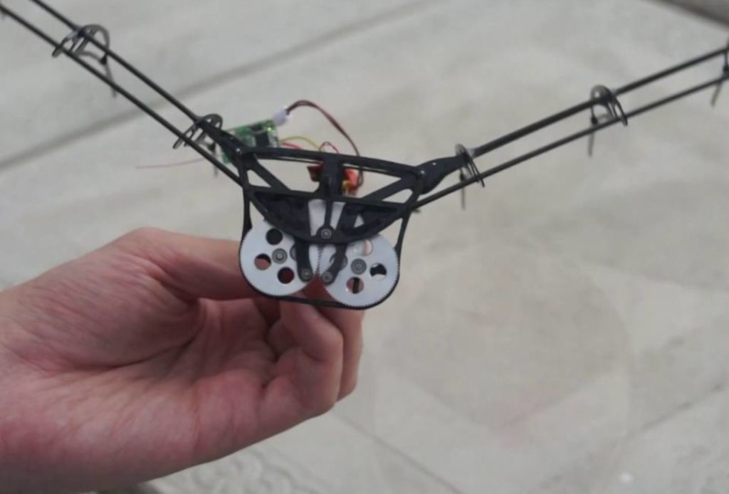
While much less common than quadcopters or airplanes, if you want a device that truly soars like a bird, you need an ornithopter. To help others make their own flying contraption, YouTuber Amperka Cyber Couch is outlining the build process in a video series starting with the one seen below.
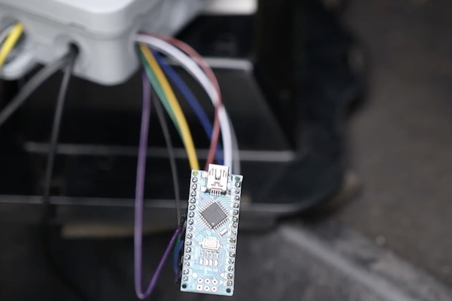
Construction is also very well documented in his project write-up, and a clip of it in-flight can be found here. The bionic ‘bird’ uses a BLDC/ESC combination to turn a gearbox that flaps its wings, and an onboard Arduino Nano for control.
Communication is via an MBee 868 wireless module, which links up to an Arduino Uno base station that provides its user interface.
Keytars may have had their moment of popularity in the 1980s, but instruments of the day can’t hold a candle to “The Blade” by makers Sam Wray, Siddharth Vadgama, and Greig Stewart.
The musical device feeds signals from a pair of Guitar Hero necks, along with a stripped down keytar from Rock Band, into an Arduino Mega. This data is then sent to a Raspberry Pi running PD Extended, and is used to control a pair of Game Boys to produce distinct 8-bit sounds. Audio output can be further modified with a Leap Motion sensor embedded in one of the two necks.
What makes up The Blade?
– 3D-printed housing
We custom modeled and printed a housing for the instrument to ensure it would be ergonomic to wield, hold together with all the components, and also look badass.
– Two Guitar Hero necks
The necks, hacked off a couple of old Guitar Hero controllers, were totally rewired to output the button presses to jumper cables.
– Arduino Mega
All the wiring from the Guitar Hero necks fed into the Mega, which then registered the button presses and output appropriate MIDI signals over USB serial into the Raspberry Pi.
– Rock Band keytar
We stripped this down to the bare keyboard and had the MIDI also going into the Pi.
– Raspberry Pi
Taking in all the MIDI, and running PD Extended we got this to manage and re-map all the button presses we needed. This then output to a MIDI thru box.
– Arduino Boy
This fed the MIDI signals from the thru box into the Game Boy.
– Game Boy
These were heart. With MIDI fed in from a multitude of sources, the Game Boy, running mGB, was the synthesizing the signals into sound, output via a standard 3.5mm jack.
– Leap Motion The Leap Motion was used for further sound modulation.
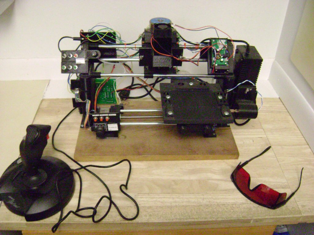
While having a huge workshop with every tool imaginable is ideal, if you have limited funds and/or space, then Mark Miller’s gantry-style machine could be just the thing you need.
In this setup, the workpiece moves via a stepper motor and a rod system on the bottom, while top support rods accommodate interchangeable tooling.
Tools compatible with the machine (so far) include a 10 watt laser, marker, knife for stencil carving, and a motor/router bit combo for light milling operations. An Arduino is employed for control, while user interface is provided by a series of buttons and a joystick.
Miller even wrote custom software to transform CAD files into sketches that can be directly loaded onto the machine.
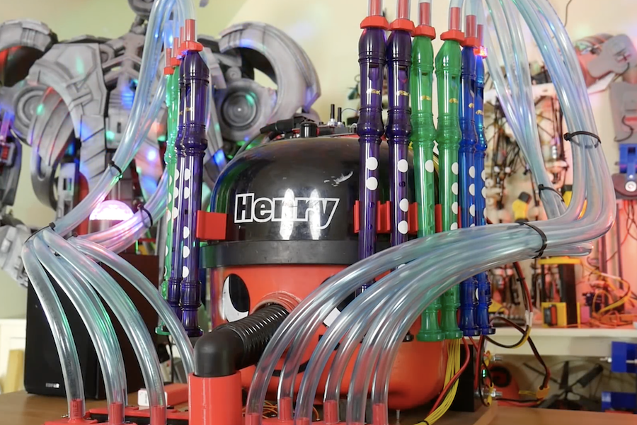
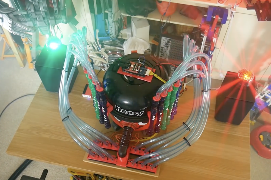
When you see a vacuum cleaner, most people see a useful implement to keep their carpets clean. James Bruton, however, envisioned another use—as a musical instrument. His new project, which made its appearance this year on April Fools’ Day, sucks air through 12 recorders, allowing it to play a full octave and the melody and lead from “Africa” by Toto… or so he’d have you believe!
In reality, power for his instrument comes from a separate Henry Hoover in another room, blowing air through the normally-suction tube of the broken device on the screen. An Arduino Mega, along with a MIDI shield, enables it to open and close air lines to each of the 12 recorders as needed.
Check out how it was made in the first video below and the original fake in the second.
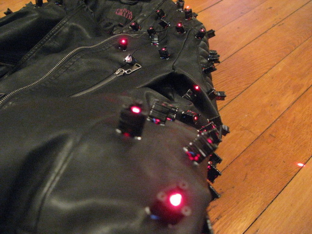
Your leather jacket might look cool, but one thing it’s missing—unless you’re maker “abetusk” or perhaps a Japanese musician—is lasers!
After seeing Yoshii Kazuya’s laser-spiked outfit, ‘tusk decided to create an excellent version of the getup by embedding 128 laser diodes embedded in his own jacket. These lasers are powered by an Arduino Nano, along with a pair of I2C PWM output boards, allowing them to be switched in sets of four.
The lasers can be controlled either by joystick, via a microphone in order to react to sound, or in a looping ‘twinkle’ pattern.
More information on the project is available in this write-up as well as on GitHub, which includes Arduino code and other files needed to build your own.
After seeing Wei Chieh Shi’s laser jacket design, I wanted to create my own. These instructions show how to modify a jacket to add laser diodes and control them electronically to produce different laser light patterns. The laser diodes give the jacket an appearance of being “spiky”, like having metal spikes but with red laser light. The effect is especially striking in environments with fog or smoke as the laser light path shows a trail from where it originates.
The concept and execution is relatively simple but care has to be taken to make sure that the electronics, wiring and other aspects of the jacket don’t fail when in use. Much of the subtlety and complexity of the project is providing proper wire routing and making sure that strain relief for the electronics and connections is provided so that it’s resilient under normal wear.
Assuming the basic parts are available (soldering iron, multimeter, wire strippers, laser cutter, etc.) I would estimate that this project is about $300 in raw materials and about 20 hours worth of labor.
Depending on the battery used, the jacket can operate for about an hour or two continuously. Spare batteries can be carried around and used to replace the depleted batteries if need be.
This incredible word clock is controlled by 114 servos
Arduino Team — April 8th, 2019
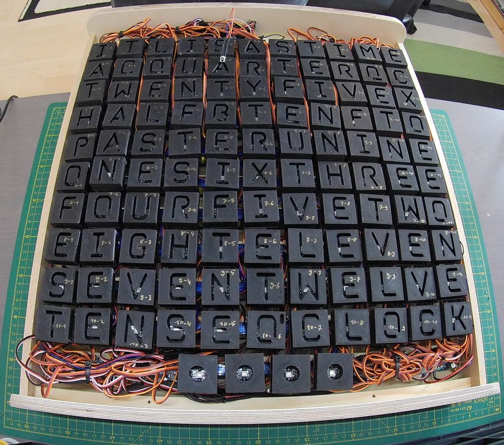
Word clocks normally use an array of lights to show the time, and although this project does use lights, how it works is much different than others.
LEDs for the device are hidden behind a thin layer of PVC, while 114 tiny SG90 servos move the lights and their 3D-printed frames back and forth. The result is a stunning display where the time is spelled out by the appropriate characters. These progressively come into focus, setting them apart from inactive letters which appear to fade into the background.
An Arduino Nano drives the assembly, along with an infrared controller setup and an RTC module for accurate timekeeping. A demo can be seen in the first video below, and the very involved build process is highlighted in the second clip.
What has 114 LEDs and is always running? As you may know the answer is a word clock. What has 114 LEDs + 114 servos and is always moving? The answer is this servo controlled word clock.
For this project I teamed up with a friend of mine which turned out to be a must because of the large effort of this build. In addition, my electronic and his mechanical skillset complemented each other quite well. The idea for this adaptation of the popular word clock came to us while we were making a regular one as Christmas gift. There, we noticed that it is also possible to project the letters from the back onto a white sheet of paper. At the time this was only a workaround solution to hide our crappy craftsmanship since we ended up with a lot of bubbles while attaching a vinyl sticker with the letters to the back of a glass plate. We then noticed that one can achieve interesting effects when bending the sheet of paper since the letters change size and become blurred. This made us come up with the idea to make a word clock where the letters are projected from the back onto a screen and can be moved back and forth to change the size of the projected image. At first we were a bit reluctant to build this project because of the costs and effort it takes when you want to move each of the 114 letters individually. So we tossed with the idea to make a version where just every word that is used to display the time can be moved back and forth. However, after seeing that the Epilog contest was coming up on Instructables asking for epic projects, and also after finding relatively cheap servo motors, we decided to go all the way and make a proper version where each letter is individually controlled by a servo
Good luck to OKdo, a brand new global technology company in the microcontroller and IoT space
Arduino Team — April 8th, 2019
OKdo’s focus is to create an ‘outstanding’ experience for all microcontroller and IoT customers, whatever their background, goals and ambitions. Bringing them the latest products, solutions and ideas to inspire and enable them to create technology that makes life better.
Visit OKdo’s new website to see the Arduino-based inspirational Industrial case study where Fluid Intelligence’s oil performance monitoring service enables industrial customers in the Logistics, Pulp & Paper, Manufacturing, Chemical and Energy sectors to maximise their operational reliability and reduce the waste generated by up to 50%.
“We’re excited to be partnering with OKdo. With our roots in open source, Arduino has transformed into a company that serves professional designers by providing complete IoT platforms, as well as continuing to enable students, educators and makers to innovate by making complex technology simple to use. There are a lot of enterprises that need simple and secure technology for adding connectivity to their devices, together, Arduino and OKdo can make that happen,” explained Massimo Banzi, CTO and Co-founder of Arduino.
“At OKdo we’re excited to work with Arduino to help them meet their objectives and grow their business. We support makers, entrepreneurs, start-ups and global businesses turn their visions into reality. Like Arduino, the philosophy behind OKdo is to put technology in the hands of those who have the biggest potential. Together with Arduino we can work with customers and businesses to help them do something amazing,” commented Richard Curtin, SVP Technology at OKdo.
Listen to the best of the ‘holdies’ with this Arduino-enabled desk phone
Arduino Team — March 30th, 2019
If you’ve ever thought that your life needs a little more hold music in it, then this Greatest Holdies phone from FuzzyWobble could be just the thing.
The heavily modified device uses the shell of an old-style desk phone, but adds an Arduino Mega, a Music Maker Shield, and an ultrasonic rangefinder for “enhanced” abilities.
Now, when someone comes near the phone, it rings automatically, treating the person curious enough to pick it up to a selection of hold music. Users can choose the tune playing via the phone’s keypad, which is wired into the Arduino, along with the original headset switch that detects when the phone has been picked up.
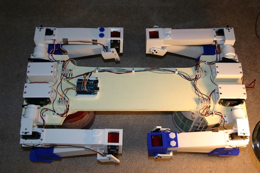
Would you like a dog? Would you like a robot dog? If so, then this build by Michael Rigsby could be a great starting point.
Rigbsy’s robotic pet features four servo-driven legs, with two-axis shoulder movement, as well as an articulated knee joint. As seen in the video below, it’s capable of picking itself up off the ground, and can then walk using a slow side-to-side gait.
An Arduino Uno uses the majority of its I/O pins to control the legs, and as of now, it travels forward with no directional control or sensor input.
Instructions for the project, along code and 3D print files, are available in Rigsby’s write-up.
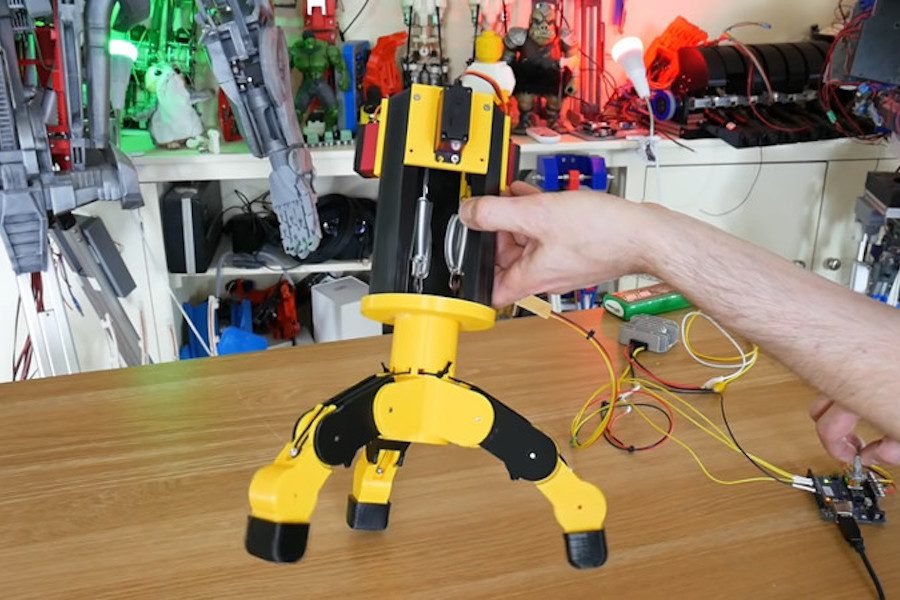
In a variety of robotic situations, you’ll need some sort of gripper. In this project, James Bruton attempts to create a force-controlled, three-fingered assembly using an Arduino Uno along with a trio of servos.
Instead of directly controlling the grip fingers, the 3D-printed device is held open with bungee cables. When it’s time to clamp everything down, the servos wind up the cables attached to the inside of the fingers, similar to how human tendons work.
To correlate servo inputs to grip force, he uses a series of springs to allow some amount of compliance, as well as flex sensors attached to the fingers themselves to measure the resulting positions. Arduino code for the build is available here.
The AbleChair by Advanced Fitness Components is nominally a wheelchair, but it’s capable of so much more.
The versatile wheelchair’s enhanced abilities include elevating the user to standing height or lowering for easy transfers. Additionally, the seating assembly can be flattened and positioned parallel to the ground, and even vertically as needed. This vertical position allows it to act as a gait training aid for those that are learning to walk, and the variety of positions has a number of health benefits.
The system itself is powered by Arduino along with brushless motors and sensors, while a joystick, touchscreen, and an Android app are used for control.
Riding a bicycle can be a great way to get around, and/or even to get some needed exercise. When you mix in automobile or foot traffic, though, things get a bit more complicated. This could be blamed, in part, on the fact that bikes don’t have the same running lights, turn or brake signals as motorized vehicles.
To address this problem, BLINK!’s patented Integrated Lighting System (iLS) has been designed to provide a visible communication solution that’s easily understandable by other road users.
This custom saddle—which was prototyped using an ATmega328P-based Arduino— features lighting for 270º visibility, and brightens automatically for braking when deceleration is detected. In addition, iLS includes a pair of remotely activated turn signals. This allows the rider to indicate direction changes without removing his or her hand from the handlebars to awkwardly point.
BLINK! has been embedded into a wide range of saddles and installation should be fairly straightforward. Not only will it certainly help enhance road safety, iLS will look fantastic while doing so.
Arduino Day is quickly approaching and we are blown away by the amazing support of the Arduino community, with over 620 events in more than 100 countries scheduled for March 16th.
As recently announced, the Official Arduino Day (register here)—directly organized by the Arduino team—will be held in Milan at the Milano Luiss Hub for Maker and Students, in collaboration with Manifattura Milano Camp.
The agenda of the official event includes an exhibition of Arduino projects, free kids activities, several keynotes by Arduino team members, and last but not least, an ‘Ask Me Anything’ with Massimo Banzi. The talks and the AMA will be live streamed via Arduino’s homepage, YouTube, and Facebook.
Here’s a look at the Official Arduino Day’s program:
11 AM (CET): Doors open and exhibition of Arduino projects, in collaboration with WeMake
2:30 – 5:30 PM: EDU activities for children ages 5 to 15
1:45 – 3:15 PM: Talks by local makers, in collaboration with WeMake (in Italian)
3:30 – 5:30 PM: Keynotes by the Arduino team. These sessions will be streamed on Arduino’s homepage, YouTube, and Facebook.
3:30 – 3:35: Welcome by Massimo Banzi and Fabio Violante
3:35 – 3:50: The State of Arduino with Massimo Banzi and Fabio Violante
The AMA will also be streamed on the Arduino homepage, YouTube and Facebook. Have a question? Please register on the Arduino Forum and submit it by 6:45 PM (CET) at this link.
We look forward to celebrating Arduino Day with everyone! In the meantime, don’t forget to share your events on social media using the hashtag #ArduinoD19.
Mancano poche ore ad Arduino Day, e siamo grati ed emozionati per l’incredibile supporto della nostra Community, che organizzerà nella giornata del 16 Marzo 2019 oltre 620 eventi in oltre 100 nazioni.
Come annunciato di recente, Official Arduino Day, ovvero l’evento direttamente organizzato dal team Arduino (registrazione qui) si terrà a Milano presso Milano Luiss Hub for Maker and Students (Via Massimo D’Azeglio, 3 – zona Porta Garibaldi), in collaborazione con Manifattura Milano Camp.
L’agenda dell’evento ufficiale include una mostra di progetti Arduino, delle attività edu per bambini/e teenager dai 5 ai 15 anni, un programma di talk con il team Arduino e, infine, una sessione di Ask Me Anything con Massimo Banzi. Le talk e l’AMA saranno trasmessi in streaming sull’homepage di Arduino e sui canali Youtube e Facebook .
Ecco il programma di Official Arduino Day a Milano:
11.00 AM: Open Day e mostra di progetti Arduino, in collaborazione con WeMake
1.45 – 3.15 PM: Community Talk a cura di maker locali, in collaborazione con WeMake
2.30 – 5.30 PM: Attività educative per bambine/i e teenager. Le attività sono gratuire e continuative, non serve prenotazione.
5-8 anni: Laboratorio di pasta modellabile conduttiva Anche i più piccoli possono giocare con l’elettricità! Con la pasta modellabile si può dare spazio alla manualità e alla creatività, con (in più) la magia dei led!
8-12 anni: Laboratorio di tinkering “Voglio Fare l’Inventore” Oggi tutti possono fare gli inventori! Flussi di energia, luci, suoni e movimenti non sono mai stati così facili da realizzare. Programmando con i sensori e attuatori, si possono costruire un’elica, un semaforo e addirittura un braccio robotico.
12-15 anni: Laboratorio di robotica “mBot and basic robotics” I robot sono tutti intorno a noi, non solo umanoidi ma anche automobili ed elettrodomestici! Con un’ app, cacciaviti e un pizzico d’ingegno, è possibile imparare le prime mosse per dargli vita e controllarli!
3.30 – 5.30 PM: Talk con Massimo Banzi e Arduino team. Le talk saranno disponibili via streaming sui canali social Arduino.
3.30 – 3.35: Welcome con Massimo Banzi e Fabio Violante
3.35 – 3.50: The State of Arduino con Massimo Banzi e Fabio Violante
Anche l’AMA (Ask me anything) sarà trasmesso in streaming sulla homepage di Arduino e sui canali Youtube e Facebook. Vuoi fare una domanda? Per favore, registrati sull’Arduino Forum e invia la tua domanda entro le 6.45 cliccando qui.
Non vediamo l’ora di festeggiare Arduino Day, nel frattempo non dimenticarti di condividere il tuo evento sui social con l’hashtag #ArduinoD19.
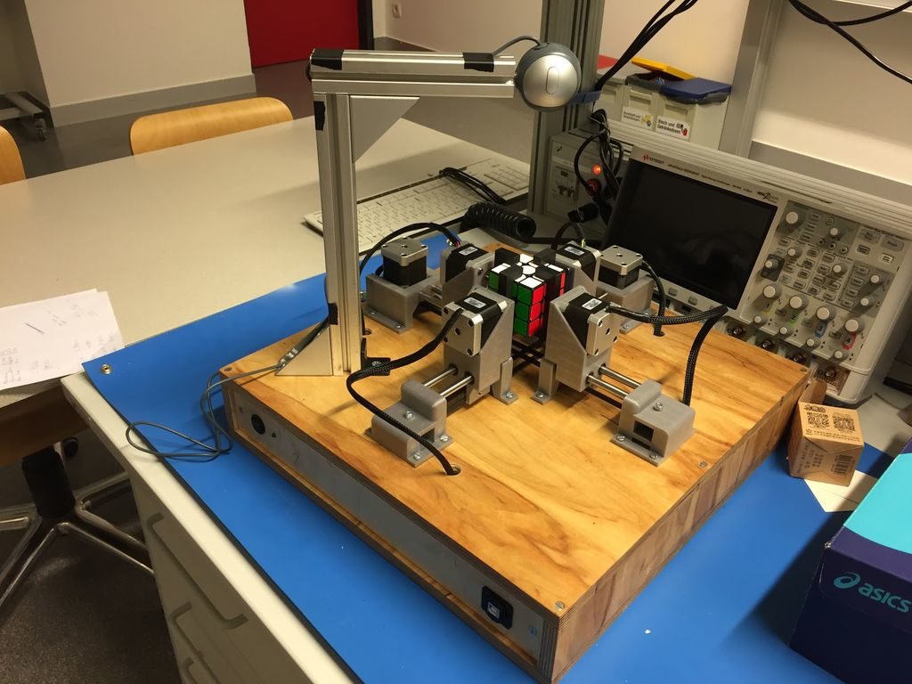
Q-Bot is an Arduino Mega-driven Rubik’s Cube solver
Arduino Team — March 14th, 2019
Rubik’s Cubes seem to have been most popular in the 1980s, but never really went away. As such, if you have one lying around your house unsolved, why not ‘simply’ construct a machine to do this for you?
One possibility is the Q-Bot, outlined here. While it won’t break any world records, it’s a solid-looking assembly that appears to be relatively easy to build.
The Q-Bot features six NEMA 17 stepper motors, four of which turn one face at a time. When needed, the other two use timing belts to alternatively pull opposed stepper motor pairs back, allowing the other two to rotate the entire assembly. An Arduino Mega is utilized to control the steppers via a custom shield, with a computer running the Kociemba’s Algorithm.
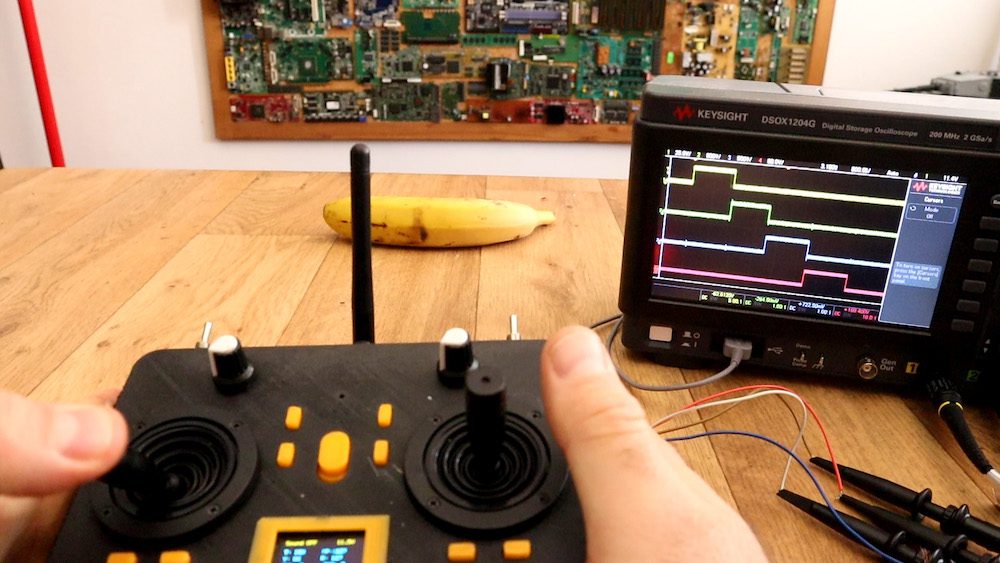
This DIY radio controller resembles one you’d find on the market
Arduino Team — March 13th, 2019
If you’ve ever considered constructing your own wireless RC transmitter, be sure to check out this build by Electronoobs.
The device uses an nRF24L01+ module to transmit inputs from a pair of joysticks and toggle switches, along with an Arduino Nano for interface and control.
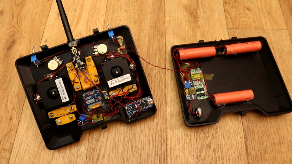
What sets this project apart from his previous versions, however, is the very nice 3D-printed enclosure for the electronics and a pair of high-quality joysticks that allow for precise input.
Additionally, Electronoobs’ latest design features tuning buttons to properly center the sticks, and an OLED display to show the actual input value that it’s sending to the receiver (a simple Nano/nRF24 setup for demo purposes).
Yes, I’ve made another radio controller. Why? well, I wanted to have a more commercial look. So, I’ve designed a 3D case, then I’ve used some high quality joysticks in order to have better analog read, It has an OLED screen so we could see the data we send and we could also digitally adjust the data. It also has 2 modes, linear and exponential
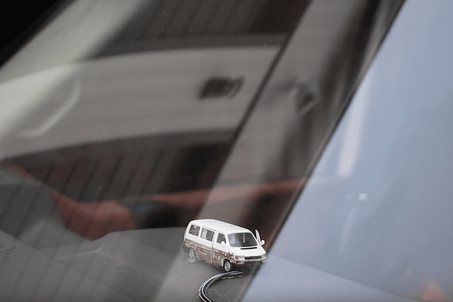
When your car door isn’t shut quite correctly, you’ll normally look down at the control panel to see what the problem is. What if, instead of indicator lights or a low-res image of your doors, you had a tiny actuated version of your vehicle on your dashboard?
Mathis Ochsenmeier’s Analogous Door Display is exactly that. It mirrors his VW van’s front and rear doors using an Arduino Nano to take in sensor information and actuate three servo motors to mimic door positions.
Now when the van’s front doors or rear hatch open or close, the little van on the dash’s doors follow suit—both a useful diagnostic tool, and an entertaining model.
Massive wall-mounted skull lights up workshop under Arduino control
Arduino Team — March 8th, 2019
While you may or may not want a gigantic backlit skull cutout haunting the wall of your workshop, this was perfect for Jay and Jamie of the “Wicked Makers” YouTube channel.
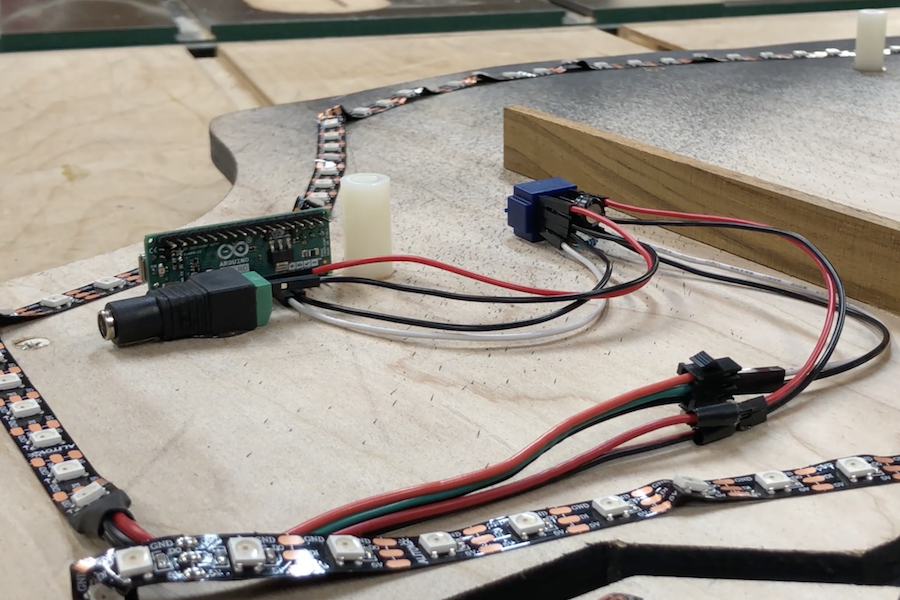
Their device is cut of two 30” squares of plywood with a CNC router. This forms a base layer that holds everything off the wall, while an outer layer provides a nice circuit/skull texture.
They affixed WS2812B LED strips to the base layer, controlled by an Arduino Micro. These strips shine off the wall for a glow through the edges, along with circuit board style cutouts inside the skull, diffused using wax paper.
Arduino code and the circuit diagram are found in the project’s write-up if you’d like to construct your own!
While you might see a CRT by the side of the street and think noting of it, Ryan Mason has come up with a novel use for five of them in a row called the Cathode MK1.
This set uses the Unity game engine along with an Arduino board to spread games across five tube TVs arranged side-by-side.
In order to keep project costs down, Mason’s gaming rig is restricted to displaying a game signal on one TV at a time. This makes gameplay even more interesting, especially considering that the way that each TV handles a loss of signal contributing to the experience.
Several games are available for this unique system, including Long Pong AKA Pooooong, where a ball bounces from screen to screen as shown in the clip below.
Omni-wheel robot slides across the paper as a mobile plotter
Arduino Team — March 8th, 2019
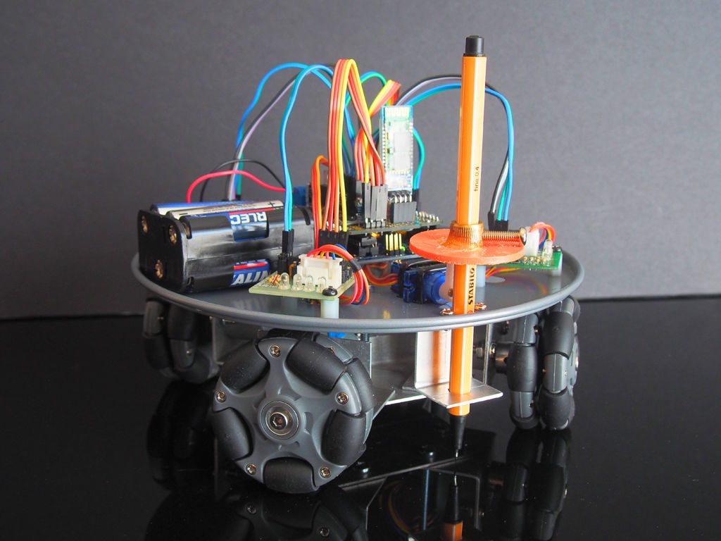
Retired maker “lingb” created an omni-bot, with four wheels that allow sliding motion in the X/Y plane courtesy of their perpendicular rollers. While that alone would have been a fun build, he also attached a pen, along with a servo-based lifting mechanism, turning this robot into a free-range plotter!
The device is controlled by an Arduino Uno and Bluetooth module, and takes movement commands via a linked smartphone or tablet. Four 28BYJ-48 stepper motors with ULN2003 drivers move each wheel, though outputs are shared between opposite motors to save on I/O.
This means that rotating the robot isn’t possible, but as shown in the video below, this isn’t needed to plot straight and curved lines with good accuracy.
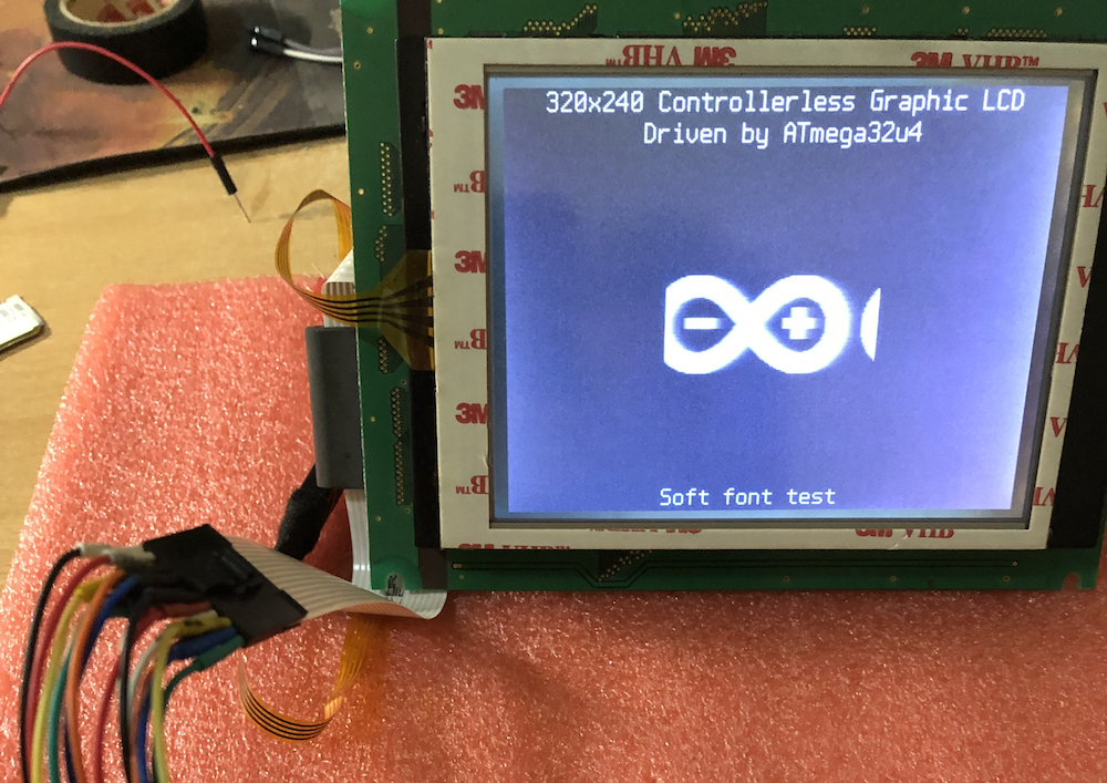
As hardware hackers, we’re always on the lookout for discarded components that can be re-purposed into something even more awesome. One such class of component that you may find is the controller-less graphics LCD modules, which can be found on old copiers, tape libraries, and the like.
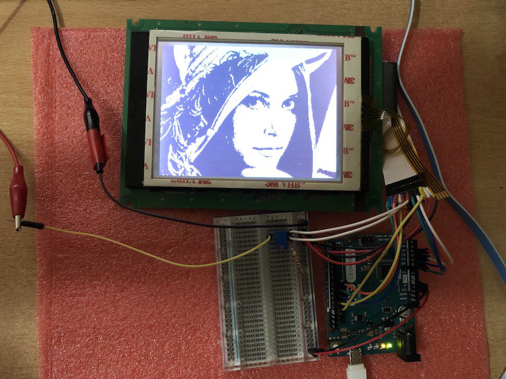
This project by Ivan Kostoski shows how to drive one of these displays with a 320×240 resolution. He’s tested his code using several types of Arduino board, such as the Uno and Leonardo, using minimal external components.
Summary Repository contains code samples for driving 4-bit parallel controllerless graphics LCD (CLGLCD) module with AVR MCU on an Arduino board, using minimal external components and staying within Arduino IDE.
4-bit Controllerless Graphics LCD modules Controllerless graphics LCD modules are antiques that can be salvaged from old copiers, tape libraries, etc… They commonly are missing, well, the controller chip, the one with the memory. Don’t go buying one of these, for Arduino usage, even if you find them on sale. They are usually industrial, have poor viewing angles, generally slow response time, and pain to work-with. There, I said my peace… But if you already have one, their size (i.e. 5.7in) or simplicity can have its uses and beauty.
I have tested this code with 320×240 STN LCD monochrome module marked as F-51543NFU-LW-ADN / PWB51543C-2-V0, salvaged some time ago from retired tape library, without the controller module (which it appears is based on FPGA and wouldn’t be of much use anyway).
The same type of interface (4-bit data) with various signal names is present on many industrial modules based on multiplexed column and common row LCD drivers, like LC79401/LC79431. Or this is what is behind the controller IC. They all have some variations like LCD drive voltage (positive or negative, depending on temperature and size of the module), backlight (LED/CCFL), some logic quirks (i.e. CL2 is ignored while CL1 is up, etc…), so maybe this code can be adapted to other controllerless modules. Module’s datasheet is necessity for the connector pinouts and timing requirements. Some modules may even generate LCD drive voltage internally, and outputting it on a pin so actual V0 driving voltage can be adjusted.
More info on the build/technique is found on GitHub, where you can also download project code and find more background on how interfacing with these devices works.
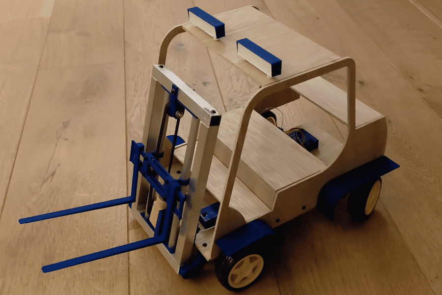
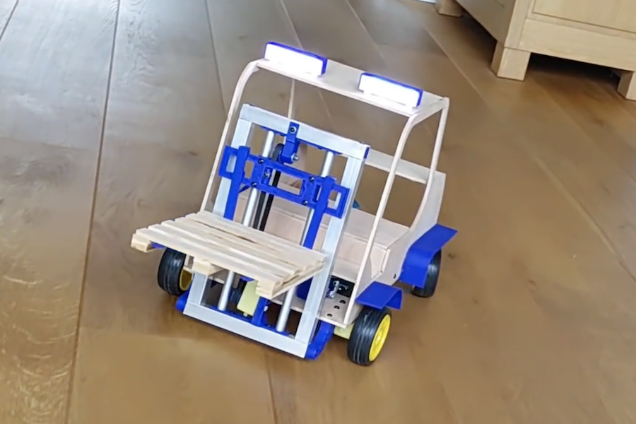
Remote control cars are interesting, but as Leon van den Beukel shows in the video below, an RC forklift can be even more challenging and fun to create.
His project was constructed using a variety of hand and automated techniques, resulting in a build that can easily manipulate tiny pallets. Forks are lifted into the air via a motor and belt assembly, and tilted with a small servo.
The device uses an Arduino Mega for control, and is linked to an Android phone over Bluetooth for user interface. Code, along with STL files and drawings, are available on GitHub and the custom Android control app can be found here.
Um dir ein optimales Erlebnis zu bieten, verwenden wir Technologien wie Cookies, um Geräteinformationen zu speichern und/oder darauf zuzugreifen. Wenn du diesen Technologien zustimmst, können wir Daten wie das Surfverhalten oder eindeutige IDs auf dieser Website verarbeiten. Wenn du deine Einwillligung nicht erteilst oder zurückziehst, können bestimmte Merkmale und Funktionen beeinträchtigt werden.
Funktional
Immer aktiv
Die technische Speicherung oder der Zugang ist unbedingt erforderlich für den rechtmäßigen Zweck, die Nutzung eines bestimmten Dienstes zu ermöglichen, der vom Teilnehmer oder Nutzer ausdrücklich gewünscht wird, oder für den alleinigen Zweck, die Übertragung einer Nachricht über ein elektronisches Kommunikationsnetz durchzuführen.
Vorlieben
Die technische Speicherung oder der Zugriff ist für den rechtmäßigen Zweck der Speicherung von Präferenzen erforderlich, die nicht vom Abonnenten oder Benutzer angefordert wurden.
Statistiken
Die technische Speicherung oder der Zugriff, der ausschließlich zu statistischen Zwecken erfolgt.Die technische Speicherung oder der Zugriff, der ausschließlich zu anonymen statistischen Zwecken verwendet wird. Ohne eine Vorladung, die freiwillige Zustimmung deines Internetdienstanbieters oder zusätzliche Aufzeichnungen von Dritten können die zu diesem Zweck gespeicherten oder abgerufenen Informationen allein in der Regel nicht dazu verwendet werden, dich zu identifizieren.
Marketing
Die technische Speicherung oder der Zugriff ist erforderlich, um Nutzerprofile zu erstellen, um Werbung zu versenden oder um den Nutzer auf einer Website oder über mehrere Websites hinweg zu ähnlichen Marketingzwecken zu verfolgen.