Schlagwort: tech

  • Reverse engineering an ’80s NeXT keyboard

    Reverse engineering an ’80s NeXT keyboard

    Reading Time: 2 minutes

    Reverse engineering an ’80s NeXT keyboard

    Arduino TeamJanuary 27th, 2022

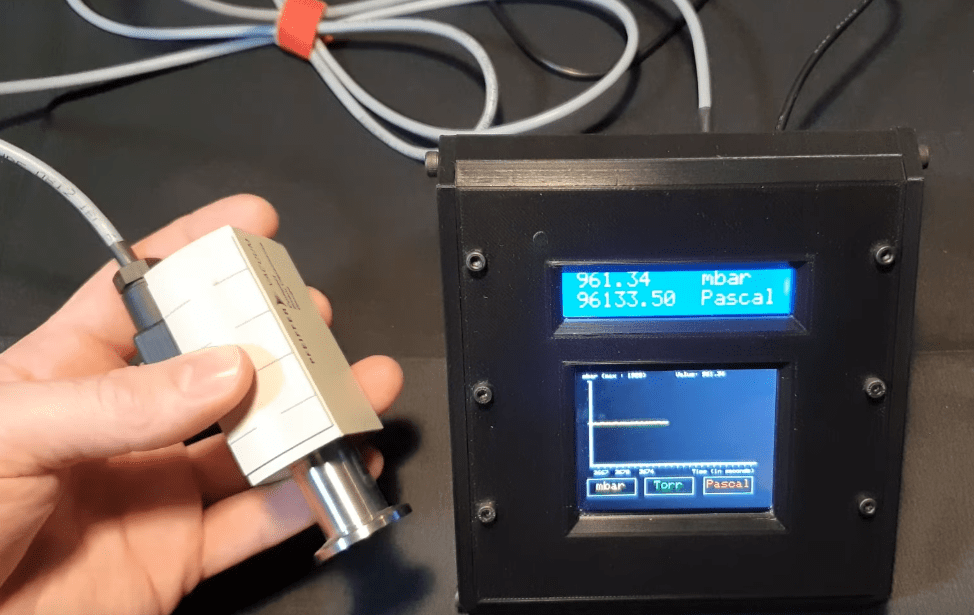
    Working with vintage computer technology can feel a bit like the digital equivalent of archeology. Documentation is often limited or altogether absent today — if it was ever even public in the first place. So you end up reverse engineering a device’s functionality through meticulous inspection and analysis. Spencer Nelson has a vintage NeXT keyboard from the ’80s and wanted to get it working with modern computers via USB. To make that happen, he reverse engineered the protocol and used an Arduino as an adapter.

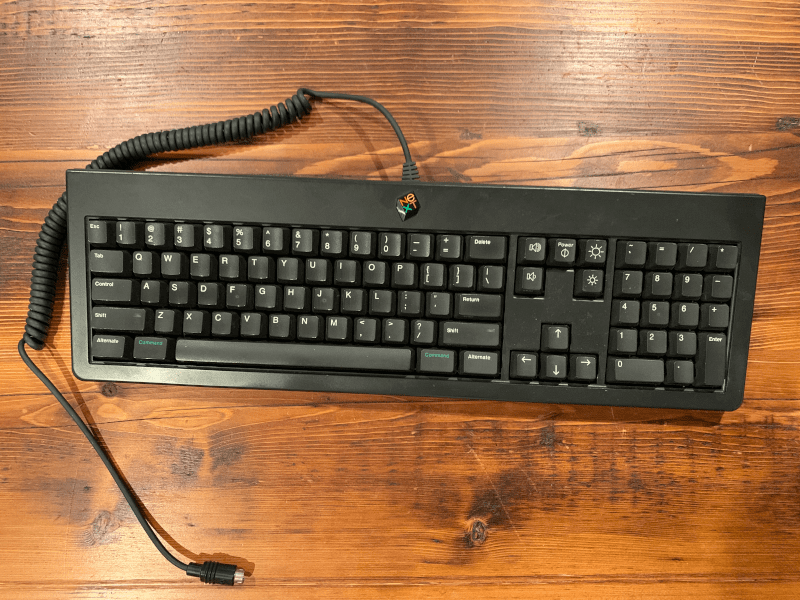
    NeXT was a computer company founded by Steve Jobs in the ’80s, in the period after he left Apple. A little over ten years later, Apple bought NeXT and Jobs rejoined the company. NeXT only released a few computers, but they are noteworthy and desirable to collectors. This particular keyboard is from 1988 and worked with the first generation NeXT Computer. Unlike modern keyboards that share the USB protocol, keyboards from this era utilized proprietary protocols. This particular model had an enigmatic protocol that Nelson became obsessed with deciphering.

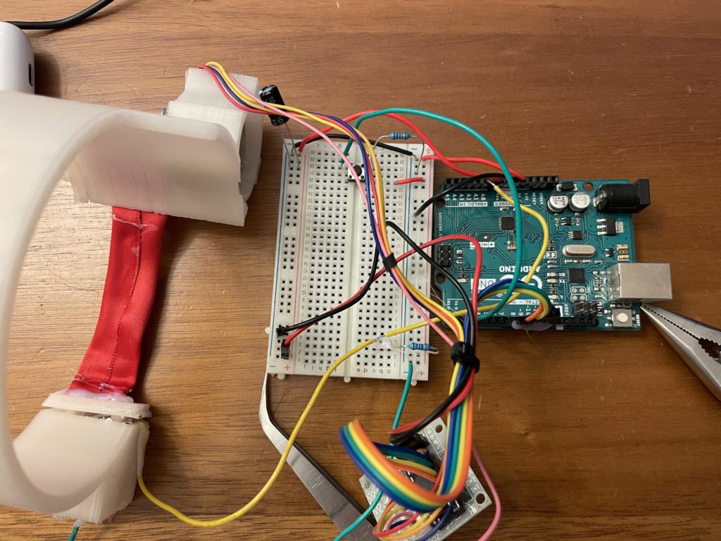
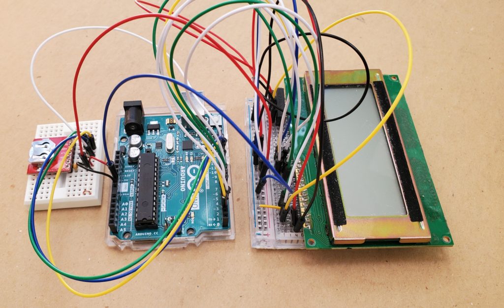
    Nelson started with an Arduino Micro with the intention of using an existing library. But that resulted in unpredictable and jumbled text. After inspecting the keyboard’s output signal with both an oscilloscope and a logic analyzer, Nelson determined that the keyboard protocol worked at an unusual 52.74 microsecond pulse width that the library didn’t account for. It turns out that that was the result of NeXT using a cheap 455 kHz resonator intended for AM radios. Every 24 ticks of that resonator, it would send a data bit (18,958 hertz equals once pulse every 52.74 microseconds).

    With this information in hand, Nelson was able to create his own Arduino sketch to analyze the signal coming from the NeXT keyboard. It can output the text via the serial console, but it is also possible to configure an Arduino as a USB HID to output the text to any modern computer.

    Website: LINK

  • This dad converted a Power Wheels into a DIY fire truck toy, complete with a siren and lights

    This dad converted a Power Wheels into a DIY fire truck toy, complete with a siren and lights

    Reading Time: 2 minutes

    Arduino TeamJanuary 27th, 2022

    After searching everywhere for an affordable ride-on fire truck toy for his daughter this past Christmas season YouTuber Jason Altice (AKA CodeMakesItGo) had nearly given up, but luckily enough was able to locate a free Grave Digger Power Wheels that he could modify into one. In its current condition, the vehicle was in bad shape so it had to first be almost completely disassembled, which led to the discovery of a bad switch that was causing the troubles. 

    Upon removing each panel and meticulously painting it with coats of primer and bright red paint, Altice moved onto the next step of including a loud siren and some lights for additional realism. He took an Arduino Nano, loaded some sounds in the form of tone melodies, and then ran the outputted signal from the digital pin to an amplifier and onwards to the horn.

    The last piece of this fire truck puzzle was figuring out how to integrate the emergency lights and make them flash in a realistic manner. Altice was able to find a string of LEDs that already had an integrated receiver, so he decoded the signal coming from the 433MHz transmitter and set the Arduino to replay it whenever the activation button on the dashboard is pressed. 

    The final result of all this work was a really cool, drivable vehicle that Altice’s daughter could use. More details on the project can be found here on Instructables.

    Website: LINK

  • This Arduino monitor helps prevent bedridden patients from getting pressure sores and more

    This Arduino monitor helps prevent bedridden patients from getting pressure sores and more

    Reading Time: 2 minutes

    Arduino TeamJanuary 27th, 2022

    For people who are recovering from a major surgery or those who have a disability, ensuring proper posture while lying down for extended periods of time is vital for reducing joint pain and other ailments that come about from a lack of movement, including pressure sores. Rodrigo Mejiasz’s project aims to solve the issue by using a small device that monitors how long a patient has been lying down in one position and alerts a caregiver when it’s time to adjust them.

    It is based around an Arduino Mega in combination with a 5” TFT screen that displays a clear graphical interface with several key datapoints and configuration options. The top of the display has choices for both the posture and the time interval between switching. Below that is a readout of the current posture, the upcoming one, and how much time has elapsed so far. Finally, there are buttons at the bottom for pausing or resuming the monitor. 

    Although simple, the Bedridden Patient Monitor has the potential to improve the quality of life of patients by reducing joint pain and the pressure placed onto certain areas of the body for extended amounts of time. You can read more about the project in its Mejiasz’s post as well as Hackaday’s coverage of the project here.

    Website: LINK

  • Capture macro photos with this Arduino-powered platform

    Capture macro photos with this Arduino-powered platform

    Reading Time: 2 minutes

    Arduino TeamJanuary 25th, 2022

    Getting that perfect up-close macro shot is touch, especially since even the smallest movement can throw off a focused image or make the subject leave the frame. This need for stability and precision is what drove Kike Glez (AKA ‘TelekikeG’ on Instructables) to build a motorized photography platform that would be able to gradually move closer/further away relative to the subject with extreme levels of granularity.

    The device utilizes an Arduino Uno as its primary microcontroller and its job is to generate pulses for the DRV8825 stepper driver, which turns the stepper motor as well as accepts user inputs from a series of five buttons — all mounted on a custom PCB shield. The board also features several TIL331 seven-segment modules for a more vintage appearance. Rather than constructing the entire platform from scratch, an old CD-ROM drive was repurposed in order to use the laser head gantry to move the subject instead. Lastly, a pair of bright lights were placed in front of the subject that provided plenty of illumination.

    To take a macro photo, the user must first input the start and stop locations of the subject, along with how much delay there should be between making a movement and taking a picture. The result is a massive collection of images, which can then be combined in software to create highly detailed macro photos. 

    For more information about Glez’s project, be sure to check out its write-up here on Instructables

    Website: LINK

  • Santagostino’s predictive maintenance for HVAC uses Nano RP2040 Connect

    Santagostino’s predictive maintenance for HVAC uses Nano RP2040 Connect

    Reading Time: 2 minutes
    Santagostino predictive maintenance Nano RP2040 Connect

    Prevention is better than cure is pretty much every respect. Heating, ventilation and air conditioning included. The Arduino Pro team has been working with Italy’s Santagostino to deploy an impressive array of predictive maintenance solutions across the region’s medical sector.

    Environment Management in Medical Centers

    Santagostino operates a network of 35 medical centers across Italy. It’s work includes diagnostic tests, procedures and setting up and maintaining suitable, medical-grade environments within the centers. The HVAC systems played an important part of that even before the COVID pandemic, but is even more essential now.

    So if a fault arose in the HVAC system it required the staff to notice it, in the first place. Then they’d need to report it, and wait for a technician to arrive and fix it. The inevitable delays could meant whole departments could potentially be unable to operate until the repairs took place.

    But that’s the nature of a breakdown. The fault occurs, it gets reported, it gets fixed. You can’t fix something that isn’t faulty, right?

    Well, maybe you can.

    Predictive Maintenance Solutions with Arduino

    Santagostino set about finding a monitoring solution that was modular, scalable, operated remotely and was adaptable enough to suit whatever HVAC system was in place. Ultimately it was built around a series of Arduino Nano RP2040 Connects. These have been installed in the HVAC units, and sending a constant stream of data back for analysis.

    The Nano RP2040 Connect’s built-in accelerometer detects vibrations, and monitors if a system is running or not. By detecting unexpected stoppages, excessive vibrations, errant motion and analyzing that data with machine learning, a network of predictive maintenance systems was built across the facilities.

    Not only is it working to alert the maintenance teams of imminent breakdowns, it allows them to schedule timely maintenance schedules before a fault occurs. A welcome side effect is that the system also allows machinery to be reduce operation when it’s not needed, saving budget and extending equipment life cycles in the process.

    There’s a case study over on the Arduino Pro website that gives you a lot more details on the system. In it you can see how it can be deployed across different industries, scenarios and sectors. And our own Stefano Implicito spoke with Santagostino’s CTO Andrea Codini about the system, which you can take a look at below.

    Website: LINK

  • Supplino is a variable benchtop power supply that you can build yourself

    Supplino is a variable benchtop power supply that you can build yourself

    Reading Time: 2 minutes

    Arduino TeamJanuary 20th, 2022

    Working with electronics requires access to stable power in a variety of voltages. Some components require 3.3V and others require 5V. Still others need 9V or 12V — there are many possibilities. You could keep a variety of wall warts on hand, but a variable benchtop power supply is a more convenient option. Supplino is one choice and this guide from Giovanni Bernardo and Paolo Loberto will walk you through how to build one.

    Supplino can accept anything from 4 to 40 volts and can output anything from 1.25 to 36 volts, with a maximum of 5A. An XH-M401 module with an XL4016E1 DC-DC buck converter handles the voltage regulation. Technically, you could use that alone to power your components. But the addition of an Arduino Nano board (or Nano Every) makes the experience far friendlier. It monitors the power supply output and drives a 1.8″ 128×160 TFT LCD screen, which displays the present voltage, amperage, and wattage.

    The Arduino receives power from a second 5V buck converter. It uses a relay to control power going to the primary buck converter. A relocated potentiometer controls the voltage. Two banana plug socket make it easy to attach alligator clips or whatever other leads your project requires. You can wrap up all of these components in a tidy and attractive 3D-printed enclosure, which is compact and fits on any desktop. You have many options for the input power, but a laptop power supply is a good choice.

    More details on the Supplino can be found in its post here.

    Website: LINK

  • DIY jet engine powered by a Portenta H7

    DIY jet engine powered by a Portenta H7

    Reading Time: 2 minutes

    Arduino TeamJanuary 19th, 2022

    Projects don’t get much more ambitious than DIY GUY Chris’ Arduino-powered jet engine. We’ve been following the work he’s done building a custom carrier board for the Portanta H7, and now we get to see it in action.

    Portenta Jet Engine

    To be honest, just building a working DIY jet engine model is incredible enough. But the model Chris has created is so much more than that.

    The 3D-printed model has a breakaway section that lets us see the engine in action. A superb educational tool that covers everything from design and control to operation. And it looks like so much fun to make and play with, too.

    His latest project puts the custom built Portenta H7 “Throne” board to use. This is a breakout, or carrier board, that he developed to explore ways to use the Portenta H7’s high density connectors. In this application it’s driving a high powered a DC motor that runs his jet engine model.

    It’s an elaborate build, with a lot of printed, moving parts. In many respects the application that the H7 is used for is pretty simple, at least on the surface. But what’s great about Chris’ latest project is that it’s an excellent example of how the Arduino board could be implemented in industrial applications.

    His excellent (and very professional) breakout board — the Throne — is a further demonstration of this, showing how adaptable devices like the H7 are in combination with custom solutions. So it’s worth taking a look at Chris’ other videos about the Throne’s development, as well as his mightily impressive DIY jet engine.

    Categories:H7

    Website: LINK

  • AutoStrap is a self-tightening strap that’s like something out of Back to the Future

    AutoStrap is a self-tightening strap that’s like something out of Back to the Future

    Reading Time: 2 minutes

    AutoStrap is a self-tightening strap that’s like something out of Back to the Future

    Arduino TeamJanuary 18th, 2022

    For wearable devices, attaching them to an arm or leg can be an annoying process since the straps used often have complicated tightening/locking mechanisms. This is what inspired one Instructables user who goes by The Puma to create the AutoStrap, a self-tightening strap system for wearable electronics similar to Marty McFly’s power-lacing sneakers in Back to the Future.

    The AutoStrap works by using a 3D-printed arm that is loaded with a spring and is actuated with a stepper motor. In order to check if the device is fully tightened around one’s arm, the spring contains 1K Ohm resistor within that goes from the rated resistance down to zero when the end is reached. This value, in turn, tells the Arduino Uno that a home point has been reached and to stop, where a button press can then reverse the process.

    Besides being a quick way to attach wearable devices for fitness or VR tracking, the AutoStrap also has potential to become an assistive device for those who might not be able to use traditional attachment mechanisms. To read more about this project, you can visit its write-up here on Instructables and watch its demo video below.

    Website: LINK

  • Arduino Week 2022: Call for speakers

    Arduino Week 2022: Call for speakers

    Reading Time: 2 minutes
    Arduino Week 2022

    This year, Arduino Day is becoming Arduino Week. Taking place on 21-26 March, 2022, we’ll have more talks, events and presentations than ever before.

    Naturally you can expect the usual excitement from the annual Arduino festival. From makers to education and industry, we’ll be bringing you the biggest and the best Arduino has to offer. But there’s also a strong focus on community for the first week-long event. And that means we want to hear from you.

    If you have a talk, idea, presentation or project you want to share, please click the button below to tell us all about it.

    What Kinds of Talks Are We Looking For?

    First and foremost, we don’t want to stifle your creativity. If you’ve got a great idea for something that you think the Arduino community would enjoy, now’s the time to share it. Makers, teachers, students, inventors, coders, influencers, pioneers, entrepreneurs, CEOs, industry, leaders, community groups; anyone and everyone is invited to join us and add to the Arduino Week celebrations.

    There might be a project you’ve built that you’d like to showcase. Or maybe you’ve been running an extracurricular program that helps people to learn about Arduino or electronics that you want to tell the world about. Did you pick up your first Arduino board during lockdown and do something cool with it? Tell us!

    It doesn’t have to be epic, either. If you’ve got a top tip about project building, coding or using Arduino that you’d love to share, let us know about it! No talk is too big, too small or too unusual to join in with Arduino Week. If it helps, entertains or showcases the community, we want to include it.

    We’re here to help flesh out your ideas, too. So don’t worry if there’s something you’d love to bring to Arduino Week but aren’t quite sure how to make it happen. Get in touch, and let’s talk about how you can get involved.

    This is going to be the biggest celebration of Arduino ever undertaken. So it’s the perfect way to demonstrate your skills, meet the global community, and get inspired for the next decade of awesome electronics projects.

    Ready to join in? Click below to fill out the form, and you could be the star of the show during the 2022 Arduino Week! 

    Website: LINK

  • Plot designs onto cups with CylinDraw

    Plot designs onto cups with CylinDraw

    Reading Time: 2 minutes

    Arduino TeamJanuary 18th, 2022

    Most plotters are planar, meaning they move in a single plane — though they often have the ability to move the tool up and down in the third axis. But if you convert one axis of the drawing plane into rotation, you get cylindrical plotting. That is how the rotary axis on a CNC machine works. If the tool moves in a third axis, you can even do conical plots. That’s exactly how CylinDraw makes it possible to plot directly onto cups and glasses.

    CylinDraw is an open source “cup-specific” plotter and engraver. It is a 2.5 axis machine with a rotary axis, similar to the famous EggBot egg plotter. Except instead of drawing onto the elliptical (in cross section) surface of an egg, CylinDraw plots onto the straight or sloped surface of cups, bottles, and similar objects. By equipping a Dremel or other rotary tool, you can also engrave onto a surface instead of drawing. If you do draw, the software also lets you swap pens to get a full color palette.

    An Arduino Nano board controls CylinDraw’s operation, including the stepper motors that rotate the cup and move the tool along the X axis. The frame and many of the parts, including the lathe-inspired chuck, are 3D-printed. But it is the software that really differentiates CylinDraw from similar plotters. With this software, you can automatically convert images into G-code toolpaths for the Arduino to follow for plotting.

    CylinDraw is currently available as a DIY hardware kit on Etsy if you want to build one for yourself.

    Website: LINK

  • AIfES releases exciting new version of TinyML library for Arduino

    AIfES releases exciting new version of TinyML library for Arduino

    Reading Time: 2 minutes

    Arduino TeamJanuary 17th, 2022

    Last July AIfES (Artificial Intelligence for Embedded Systems) from the Fraunhofer Institute for Microelectronic Circuits and Systems (IMS) was launched. This open source solution makes it possible to run, and even train, artificial neural networks (ANN) on almost any hardware, including the Arduino UNO. 

    The team hasn’t stopped work on this exciting machine learning platform, and an update just landed that you’ll definitely want to check out.

    The new AIfES-Express API

    AIfES-Express is an alternative, simplified API that’s integrated directly into the library. The new features allow you to run and train a feed-forward neural network (FNN) with only a few lines of code.

    Q7 weight quantization

    This update enables the simple Q7 (8-bit) quantization of the weights of a trained FNN. This significantly reduces the memory required. And depending where it’s being deployed, it brings a significant increase in speed along with it.

    This is especially true for controllers without FPU (Floating Point Unit). The quantization can be handled directly in AIfES® (and AIfES-Express) on the controller, PC, or wherever you’re using it. There are even example Python scripts to perform the quantization directly in Keras or PyTorch. The quantized weights can then be used in AIfES®.

    Advanced Arm CMSIS integration

    AIfES® now provides the option to use the Arm CMSIS (DSP and NN) library for a faster runtime.

    New examples to help you get building

    A simple gesture recognition application can be trained on-device for different Arduino boards, including:

    You can play tic-tac-toe against a microcontroller, with a pre-trained net that’s practically impossible to defeat. There are F32 and quantized Q7 versions to try. The Q7 version even runs on the Arduino UNO. The AIfES® team do issue a warning that it can be demoralizing to repeatedly lose against an 8-bit controller!

    This Portenta H7 example is particularly impressive. It shows you how to train in the background on one core, while using the other to run a completely different task. In the example, the M7 core of the Portenta H7 can even give the M4 core a task to train an FNN. The optimized weights can then be used by the M7 to perform the FNN with no delay, due to the training.

    Here’s a link to the GitHub repository so you can give this a go yourself.

    Website: LINK

  • Homemade Pirani vacuum gauge controller with Arduino

    Homemade Pirani vacuum gauge controller with Arduino

    Reading Time: 2 minutes

    Arduino TeamJanuary 15th, 2022

    In theory, a Pirani gauge is a very simple device for measuring the pressure of a gas within a container, as it consists of a heated metal wire that loses heat as the pressure increases internally. With this value now known, the electrical resistance can be measured and used to determine the precise pressure of a given gas. And although the sensors themselves are relatively inexpensive, the controllers they are often connected to can have a very high price, which is why YouTuber Advanced Tinkering decided to create his own digital readout

    The display uses an Arduino Mega to take in data from the sensor, convert it to a pressure level, and send it to a pair of LCDs. First, the Pirani gauge’s analog value is read with an ADS1115 ADC, which has 16 bits of resolution, and from there the value is converted to pressure using the calibration constant for air and a unit coefficient. The Mega then writes this information to the unit’s 16×2 character LCD module and plots points along a graph shown on a 3.5” TFT screen. Additionally, pressure data is sent via USB to a host machine where it can be read by an external program such as the Arduino Serial Plotter tool.

    This DIY controller is a great showcase of how one can build their own scientific equipment for far cheaper than is otherwise available. To see more about this project, watch Advanced Tinkering’s video below!

    Website: LINK

  • Have you checked out our winter sale?

    Have you checked out our winter sale?

    Reading Time: < 1 minute

    Arduino TeamJanuary 14th, 2022

    Start the year with a new Arduino hardware component. Or two, or three! Dozens of our products are currently discounted at 20% for our annual winter sale. Just head over to the Arduino store and pick out all the modules, shields and carriers that fit your needs.

    We even have the MKR IoT Carrier and full MKR IoT Bundle on sale, to help you make 2022 the year of your first Internet of Things project. There are all kinds of connectivity available, from LoRa to GSM and NB communication, so you can get to work on a connected project that hooks straight up to Arduino Cloud, too.

    So what are you waiting for? They’re selling out fast

    Stock up on the hardware you need at 20% off, and don’t forget to share all the projects you create with your Winter Sale loot using the hashtag #arduinoproject and #madewitharduino! 

    Website: LINK

  • This clock counts down to retirement

    This clock counts down to retirement

    Reading Time: 2 minutes

    Arduino TeamJanuary 14th, 2022

    For most people, the idea of retiring is a very exciting thought. Finally, after decades of hard work, you can clock out for the last time and spend the rest of your life relaxing and enjoying your leisure years. RdRnr318’s coworker updates her whiteboard every day to countdown the number of days until she gets to retire. To save Martha some effort and reduce the office’s marker budget, RdRnr318 built this “Nearly-Autonomous Retirement Countdown Display” to replace the whiteboard.

    This device does exactly what it says on the tin: it shows a countdown timer with the number of days until Martha reaches her retirement. It also displays the countdown in seconds, minutes, and hours, so Martha can get granular with her retirement daydreams. This device needs no buttons for setting the time, because RdRnr318 programmed it specifically for Martha. Her retirement date is hardcoded and there is a real-time clock with a battery backup, so it can automatically calculate the countdown even after losing power.

    An Arduino Uno board controls the device. It monitors the current time using a SparkFun DeadOn DS3234 RTC Breakout and displays the countdown on a simple 20×4 character LCD screen. Power comes from a wall wart or, in case of a power outage, a CR2032 battery backup. The case is a standard prefabricated enclosure box. The sketch is straightforward and pulls the current time from the RTC. It then subtracts that from Martha’s retirement date to get the remaining time. It even accounts for the differing number of days in each month and leap years!

    Website: LINK

  • The 2021 Arduino Open Source Report is out

    The 2021 Arduino Open Source Report is out

    Reading Time: 2 minutes

    Arduino TeamJanuary 13th, 2022

    Arduino Open Source Report for 2021

    We’re excited to announce the Arduino Open Source Report for 2021 is now available, offering many insights into the development of our open-source ecosystem during the past year.

    In this retrospective report you’ll learn about the activities Arduino carried out in the last twelve months, thanks to the hard work of the employees, contractors and volunteers on our team and to the passion of our vibrant community, fueling our mission every day.

    We’re proud of the many achievements we celebrated in 2021. It was one of the busiest and most productive years in Arduino’s history of commitment to open source.

    We launched a number of new open source hardware products, software tools and libraries. We also upgraded existing assets, heavily refactoring some core pillars of the Arduino framework (IDE, library index and more) ,making them robust enough to support the growing Arduino user base.

    The document also highlights key contributions from the Arduino community – libraries, cores and more – that were made during the year. We’re grateful for all the active maintainers and contributors that put Arduino in a league of its own, and strive to give everyone proper credit.

    We invite all of you to join the community and become active contributors. There’s a lot to do! For each sub-project, the report points out where you can join us and make a difference.

    So, are you ready to dive in? Download the Arduino Open Source Report 2021, and please share your comments and get in touch with us on the Arduino Forum. We want to read your feedback and understand what we can do together in 2022 to ensure Arduino keeps getting better and better.

    Website: LINK

  • Let your ideas take flight in the Arduino Cloud Games

    Let your ideas take flight in the Arduino Cloud Games

    Reading Time: 3 minutes
    Arduino Cloud Games

    Arduino’s brand new initiative, the Arduino Cloud Games, is now live and accepting submissions.

    This new program is a way to build a community showcase of the most creative, innovative ideas that show the vast potential and scope of connected projects. Let’s take a look at how you can get involved, and let your ideas take flight.

    What are the Arduino Cloud Games?

    Based around five different categories, the games are similar in nature to an athletics event. Pick your specialty, enter the event, and go for gold!

    Step 1: Pitch your idea

    You don’t even need to have your project built and ready to join in. Just pitch your idea, and the 100 most creative will be sent a free Oplà IoT Kit to incorporate into their projects.

    Your project idea must include use of the Arduino Cloud, and if you’re selected for a free Oplà IoT Kit, that must be included as part of your build.

    You’ve got until 23rd January, 2022, to submit your application.

    Step 2: Build your project

    We’ll keep in close contact with all participants during the six weeks building phase of Arduino Cloud Games. The entire community is there to help you if you get stuck, and we want to do everything we can to help you stay on track and motivated!

    Your completed project must be submitted by 11th March, 2022.

    Step 3: Arduino Week Awards

    There are three awards up for grabs for the most creative, innovative, connected projects! Vouchers of $1,000, $500 and $250 for the Arduino Store, with the recipients being announced as part of the Arduino Week celebrations.

    So what are you waiting for? Head on over to the Arduino Cloud Games page, and give us your best connected project pitch!

    Arduino Cloud Games FAQ

    A few people have asked about various aspects of the Cloud Games, so let’s look at those right here.

    Can I still enter if I’m not selected for a free Oplà IoT Kit?

    Absolutely, yes. Your project will still need to be completed and working before Arduino Week, and make use of Arduino Cloud. The Oplà IoT Kit is recommended as a quick, versatile starting point for these kinds of connected projects, so it’s still worth serious consideration. But the Cloud Games are open to everyone.

    What if my project isn’t finished in time, or doesn’t work?

    In order to be eligible for the awards on offer, your project will have to be completed in time, be working, and still be closely related to the original pitch.

    What if I need to change some parts of my project during the build?

    We totally understand that projects evolve as you start building and testing them. And we don’t want to stifle anyone’s creativity with overly inflexible rules! So it’s completely okay if you need to adapt as you’re going. But ultimately, the objective of your project should be similar to your original pitch.

    Can I enter more than one project in Arduino Cloud Games?

    You can. Each pitch must be totally unique, and if more than one is selected you’ll still be expected to complete all projects and have them working before the Arduino Week deadline.

    Can I use other parts, components or devices in my project besides the Cloud and Oplà IoT Kit?

    Of course! Whatever your project needs to do its thing! Use whatever you like, as long as the Arduino Cloud is part of the project (and the Oplà IoT Kit, if you were selected). Let your ideas take flight!

    Do I have to return the Oplà IoT Kit when it’s finished?

    Nope, that’s yours to keep. Although we do expect participants to meet their side of the bargain, and complete the project they pitched in time for Arduino Week.

    Do I have to use every part of the Oplà IoT Kit if I receive one?

    No. The kit includes a lot of gear, features and functions. It’d be impractical to expect a project to use every aspect of it. The Oplà IoT Kit is recommended as it’s a fast, powerful way to build and control connected projects. So as long as the kit is used either in full or in part, you’re good.

    Website: LINK