Schlagwort: STL
-

4 Most Common 3D Printer File Formats in 2019
Reading Time: 26 minutesWhat is the best 3D printer file format? Which format should you use? We explain and compare the four most common 3D printing file formats: STL, OBJ, AMF, and 3MF. What is a 3D Printer File Format? 3D printers require a 3D file of an object To print a three-dimensional object, a 3D…
-

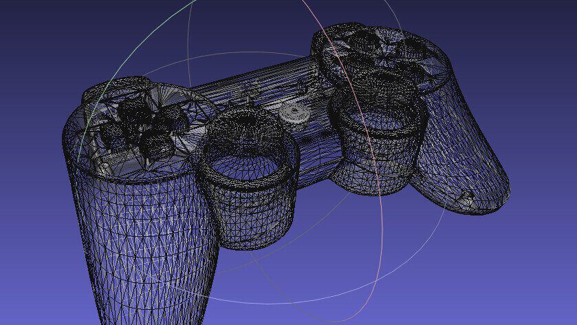
STL File Format (3D Printing) – Simply Explained
Reading Time: 18 minutesWhat is an STL file? What is it good for? How does it work? We simply explain the STL file format for 3D printing in depth. Here’s a primer on what they are and how they work, the advantages and disadvantages of their use, plus alternative file formats to consider. In this…
-

8 Most Common 3D File Formats – Simply Explained
Reading Time: 24 minutesWhich 3D file formats are there? How do they compare? What should you use? We simply explain the 8 most common 3D file formats used today: STL, OBJ, FBX, COLLADA, 3DS, IGES; STEP, and VRML/X3D. A 3D file format is used for storing information about 3D models. You may have heard of the most…
-

Wikimedia Commons Enables 3D Model Uploads and Downloads
Reading Time: 3 minutesWikimedia Commons has enabled a new feature which will allow you to upload 3D models. The first upload is a model by the #NEWPALMYRA project, honoring Bassel Khartabil. In 2015, the Wikimedia community was surveyed and a wish list was realized. On that list, number eleven is to add 3D models on Wikimedia Commons.…