Schlagwort: robots
-

Recreating Rosie the Robot with a MKR ZERO
Reading Time: < 1 minuteRecreating Rosie the Robot with a MKR ZERO Arduino Team — August 3rd, 2020 While 2020 may seem like a very futuristic year, we still don’t have robotic maids like the Jetsons’ Rosie the Robot. For his latest element14 Presents project, DJ Harrigan decided to create such a bot as a sort of…
-

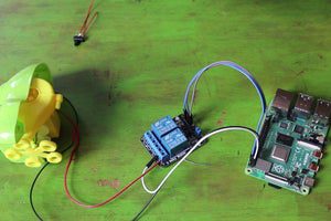
Auto-blow bubbles with a Raspberry Pi-powered froggy
Reading Time: 2 minutes8 Bits and a Byte created this automatic bubble machine, which is powered and controlled by a Raspberry Pi and can be switched on via the internet by fans of robots and/or bubbles. [youtube https://www.youtube.com/watch?v=Mp7LrYoTGsY?feature=oembed&w=500&h=281] They chose a froggy-shaped bubble machine, but you can repurpose whichever type you desire; it’s just easier…
-

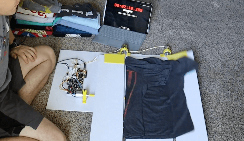
This Arduino-powered machine folds your shirts at the push of a button
Reading Time: < 1 minuteThis Arduino-powered machine folds your shirts at the push of a button Arduino Team — July 21st, 2020 Inspired by an old FlipFold TV ad, YouTuber Ty Palowski decided to make his own automated shirt folding machine. Palowski’s device is made in four folding sections, which lie flat to accept the…
-

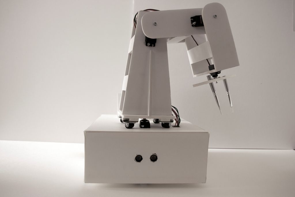
Painting robot with ‘twin’ control scheme
Reading Time: 2 minutesPainting robot with ‘twin’ control scheme Arduino Team — July 16th, 2020 For a class project, University of Stuttgart students Ekin Sila Sahin, Lior Skoury, and Simon Treml came up with a unique painting robot named the Physical Twin. The Physical Twin travels on a three-wheeled chassis and mounts a four-axis arm with a…
-

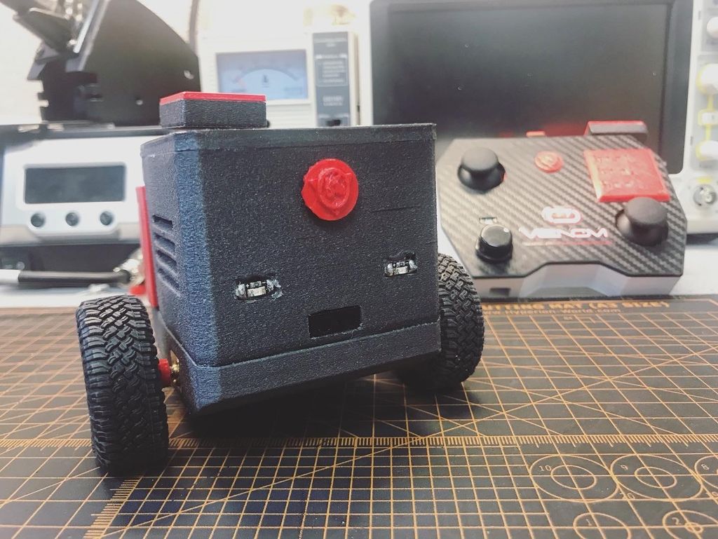
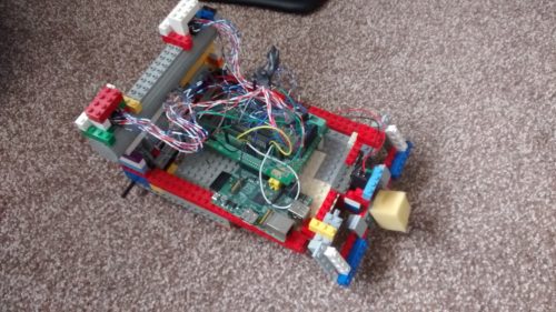
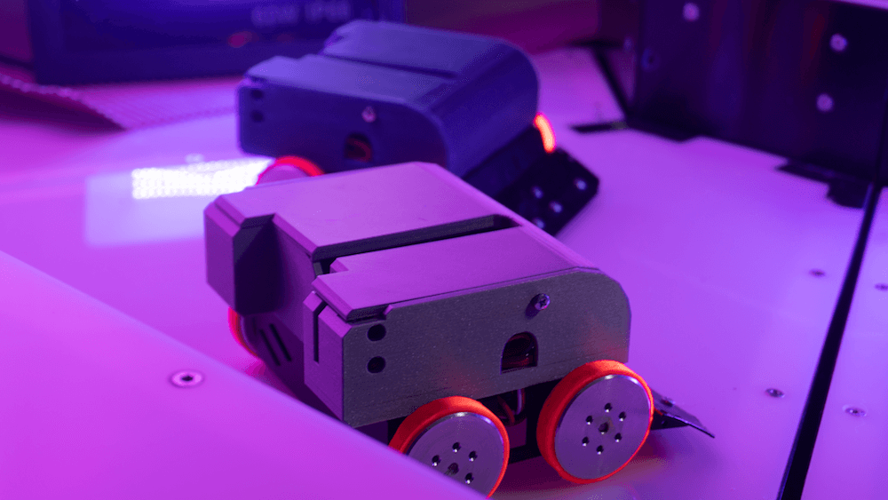
Meet MrK_Blockvader, a little mobile robot that’s lots of fun
Reading Time: < 1 minuteOne of the simplest ways to make a mobile robot involves differential steering, where two wheels move at different speeds as needed to turn and a ball caster keeps it from tipping over. The MrK_Blockvader is an excellent take on this type of bot — demonstrated in the first clip below — featuring…
-

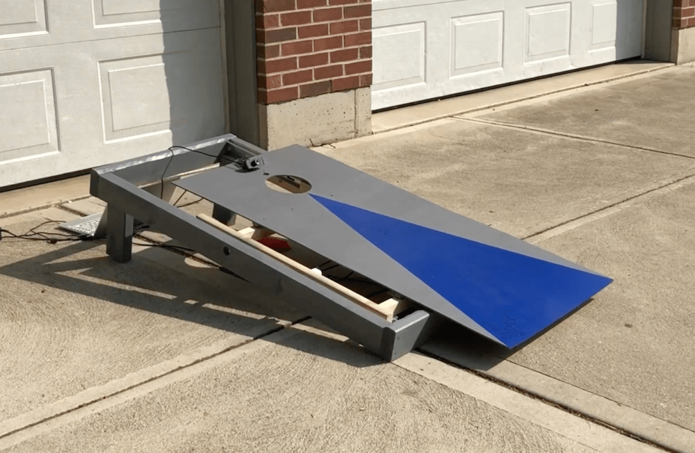
Robotic cornhole board guarantees three points every time
Reading Time: < 1 minuteRobotic cornhole board guarantees three points every time Arduino Team — July 8th, 2020 You may have seen Mark Rober’s automated dartboard or Stuff Made Here’s backboard, which use advanced engineering to create apparatuses that ensure you “can’t miss.” Now that summer is in full swing, what about a robotic cornhole board?…
-

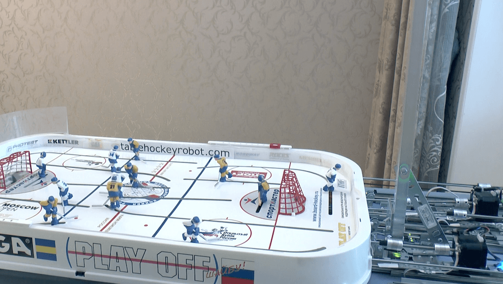
This puck-slapping robot will beat you in table hockey
Reading Time: 2 minutesThis puck-slapping robot will beat you in table hockey Arduino Team — July 3rd, 2020 Mechanical table hockey games, where players are moved back and forth and swing their sticks with a series of knobs, can be a lot of fun; however, could one be automated? As Andrew Khorkin’s robotic build demonstrates,…
-

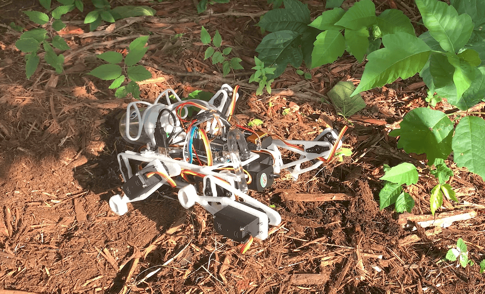
This robo-dog sprays poison ivy with weed killer
Reading Time: < 1 minuteThis robo-dog sprays poison ivy with weed killer Arduino Team — July 1st, 2020 Poisonous plants, like poison ivy, can really ruin your day. In an effort to combat this “green menace,” YouTuber Sciencish decided to create his own quadruped robot. The robotic dog is equipped with two servos per leg,…
-
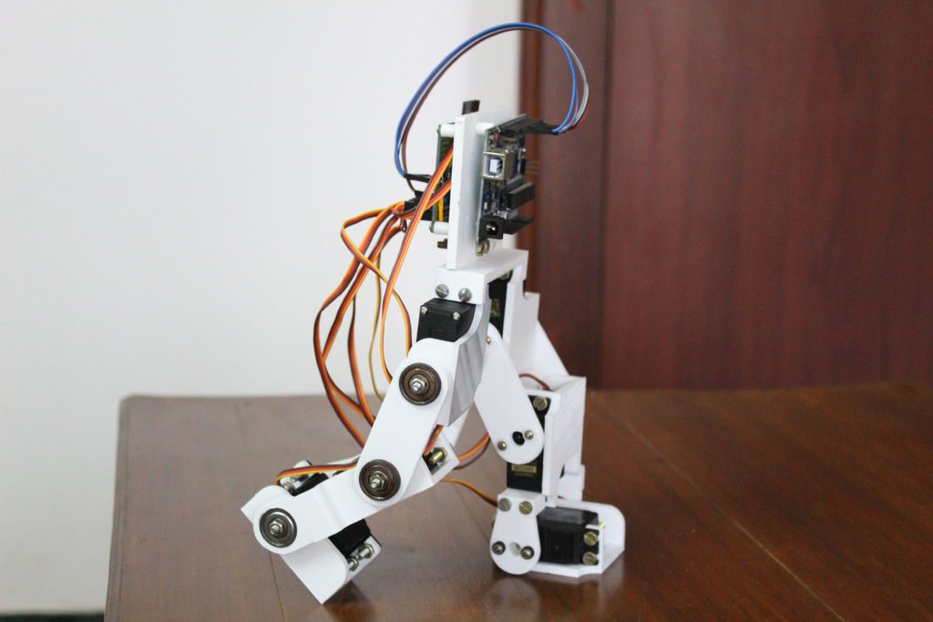
Building an Arduino-based bipedal bot
Reading Time: < 1 minuteBuilding an Arduino-based bipedal bot Arduino Team — June 21st, 2020 If you’d like to build a walking biped robot, this 3D-printed design by Technovation looks like a fantastic place to start. Each leg features three servos that actuate it at the hip, knee, and ankle for a total of six…
-

Learning with Raspberry Pi — robotics, a Master’s degree, and beyond
Reading Time: 5 minutesMeet Callum Fawcett, who shares his journey from tinkering with the first Raspberry Pi while he was at school, to a Master’s degree in computer science and a real-life job in programming. We also get to see some of the awesome projects he’s made along the way. I first decided to get…
-

Meet TELEBOT, the terrifying telepresence robot
Reading Time: 2 minutesMeet TELEBOT, the terrifying telepresence robot Arduino Team — June 1st, 2020 The Internet has been perhaps more important than ever to keep us connected these days. Available technology, however, apparently wasn’t good enough for brothers Hunter and Josh Irving, who built their own telepresence robot using parts on-hand during their own…
-

GoodBoy is a robot dog that runs on Arduino
Reading Time: < 1 minuteGoodBoy is a robot dog that runs on Arduino Arduino Team — May 27th, 2020 Daniel Hingston wanted to build a four-legged walking robot for several years, and with current coronavirus restrictions he finally got his chance. His 3D-printed robodog, dubbed “GoodBoy,” is reminiscent of a miniature version of Boston Dynamics’ Spot,…
-

Meet your new robotic best friend: the MiRo-E dog
Reading Time: 3 minutesWhen you’re learning a new language, it’s easier the younger you are. But how can we show very young students that learning to speak code is fun? Consequential Robotics has an answer…The MiRo-E is an ’emotionally engaging’ robot platform that was created on a custom PCB and has since moved onto Raspberry…
-
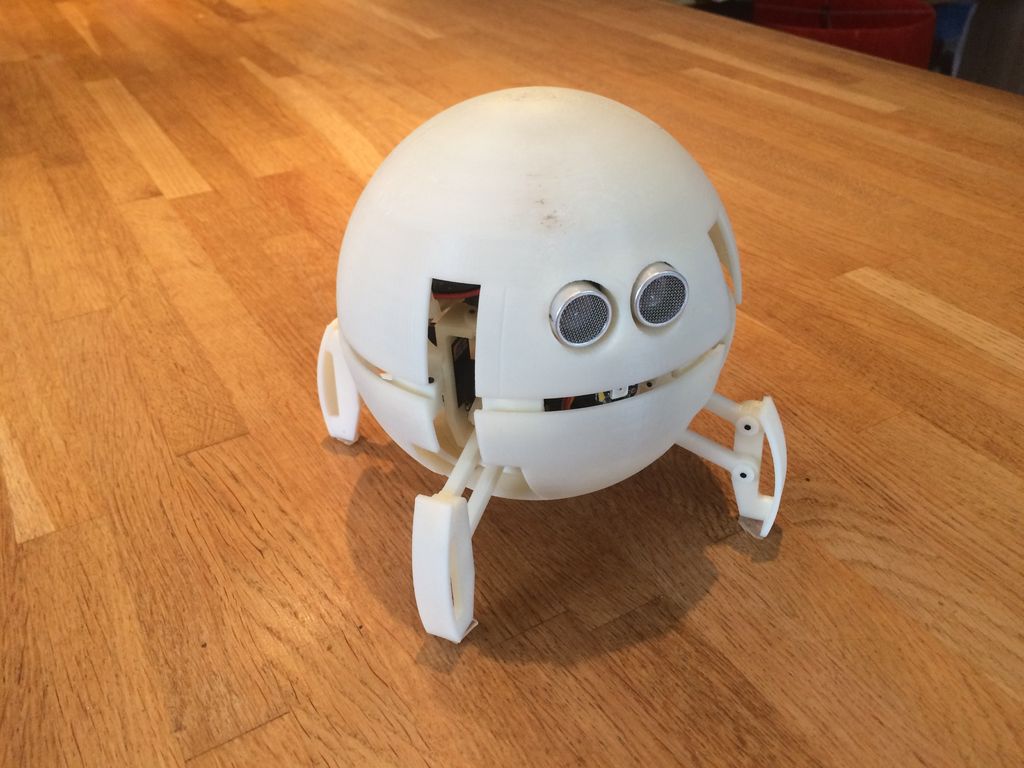
This robot looks like a ball and transforms itself into a quadruped to move
Reading Time: 2 minutesThis robot looks like a ball and transforms itself into a quadruped to move Arduino Team — May 25th, 2020 Gregory Leveque has created an adorable 3D-printed robot that not only walks on four legs, but folds up into a ball when not in use. To accomplish this, the round quadruped utilizes…
-

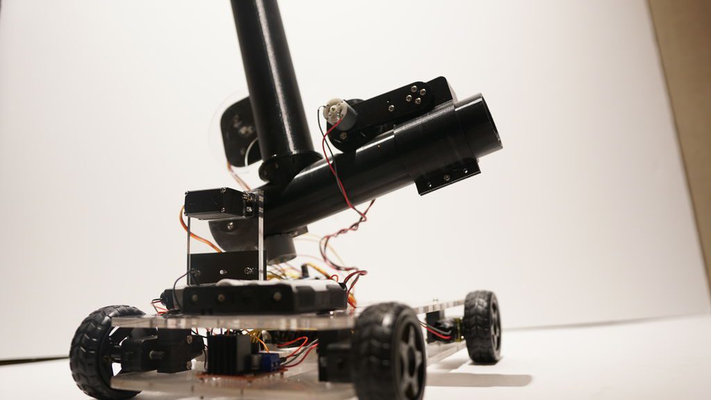
Make it rain chocolate with a Raspberry Pi-powered dispenser
Reading Time: 5 minutesThis fully automated M&M’s-launching machine delivers chocolate on voice command, wherever you are in the room. [youtube https://www.youtube.com/watch?v=hsGhCl0y1FY] A quick lesson in physics To get our head around Harrison McIntyre‘s project, first we need to understand parabolas. Harrison explains: “If we ignore air resistance, a parabola can be defined as the arc…
-

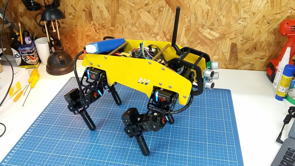
mechDOG, a 12-servo robotic pup
Reading Time: < 1 minutemechDOG, a 12-servo robotic pup Arduino Team — May 18th, 2020 Mech-Dickel Robotics has designed a beautiful quadruped robot dubbed mechDOG, which utilizes a dozen servos for motion. This gives each leg three degrees of freedom, allowing the cat-sized beast to travel a meter in 8.46 seconds. While it won’t break any…
-

This mouth mechanism is controlled by your typing
Reading Time: < 1 minuteThis mouth mechanism is controlled by your typing Arduino Team — April 21st, 2020 Will Cogley, known for his awesome animatronics, has created a robotic mouth that’s already a work of art and could form the basis of something even more amazing. The device features an array of servo mechanisms to…
-

This garbage-bot trash talked TEDx Copenhagen attendees
Reading Time: 2 minutesThis garbage-bot trash talked TEDx Copenhagen attendees Arduino Team — April 21st, 2020 For TEDx Copenhagen 2019, MAKESOME was contacted about building a trash can. Not just any ordinary waste bin, however, but one that would fit in with their theme of “expect the unexpected” by driving around and being rude to…
-
Pingo, the motion-detecting ping pong ball launcher
Reading Time: < 1 minutePingo, the motion-detecting ping pong ball launcher Arduino Team — March 11th, 2020 If you want to “enhance your athletic training regimen,” or perhaps just have a bit of fun with robotically launched ping pong balls, then be sure to check out the Pingo apparatus shown in the video below. This…
-

The Watchman is a 3D-printed robot head that follows your face with realistic eyeballs
Reading Time: 2 minutesThe Watchman is a 3D-printed robot head that follows your face with realistic eyeballs Arduino Team — March 9th, 2020 When you step out in public, you’ll often be filmed by a number of cameras and perhaps even be analyzed by tracking software of some kind. The Watchman robot head by Graham…
-

Creating an online robot fighting game using Arduino MKR1000 WiFi
Reading Time: 7 minutesThis is a guest post from Surrogate, a team of developers building games that people play in real-life over the internet. We introduced this concept last year, and have launched three games so far. Our final game of 2019 was SumoBots Battle Royale — where players from anywhere in the world can…
-

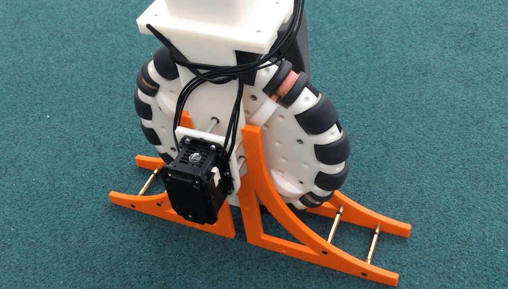
OmBURo is an Arduino-controlled unicycle robot with an active omnidirectional wheel
Reading Time: 2 minutesOmBURo is an Arduino-controlled unicycle robot with an active omnidirectional wheel Arduino Team — February 4th, 2020 Omni wheels normally contain a number of rollers arranged on their circumference, allowing them to slide left and right and perform various tricks when combined with others. The rollers on UCLA researchers Junjie Shen and Dennis…