Schlagwort: robotics
-

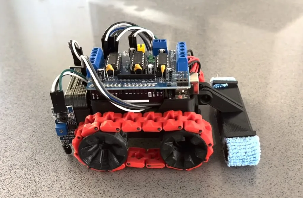
This RC tank has Möbius strip tracks
Reading Time: 2 minutesMöbius strips are often used to symbolize infinity, because they are continuous loops with only a single surface. They can’t exist in real life, because every solid object in reality has thickness — even if it is very thin, like a piece of paper. But we can construct similar objects that loop and…
-

Replicating two of history’s most iconic BattleBots with the Arduino UNO R4
Reading Time: 2 minutesWhen the BattleBots TV show first hit the airwaves in 2000, it felt like we were finally living in the future. Engineers and enterprising hobbyists from around the world would compete to build the most destructive robots, which then entered into televised mortal combat within an arena. The original series had many notable robots,…
-

This robot turns old bottles into a musical instrument
Reading Time: 2 minutesPercussion instruments are likely the first kind that humanity invented, because they’re quite simple: hit a thing and a noise happens. Different things produce different frequencies with different timbres, and glass bottles have a nice xylophonic sound to them. Because glass bottles are easy to find among discarded garbage, Jens of the…
-
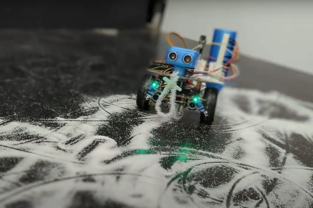
Tiny DIY Roomba cleans desks and countertops
Reading Time: 2 minutesThe future we were promised was supposed to include robot maids and flying cars. The future we got has Roomba vacuums and Southwest Airlines. But at least those Roomba vacuum robots work pretty well for keeping floors slightly cleaner. Sadly, they leave elevated surfaces untouched and dust-ridden. To address that limitation, Jared…
-

Can you smell what the Rockobot is cooking?
Reading Time: 2 minutesModern engineering is increasingly cross-disciplinary, so today’s students often take courses that would have seemed to be “outside their field” a couple of decades ago. Pelochus and their classmates at the University of Granada are studying computer engineering, but had a class that challenged them to build battlebots in order to get…
-

Teaching an Arduino UNO R4-powered robot to navigate obstacles autonomously
Reading Time: 2 minutesThe rapid rise of edge AI capabilities on embedded targets has proven that relatively low-resource microcontrollers are capable of some incredible things. And following the recent release of the Arduino UNO R4 with its Renesas RA4M1 processor, the ceiling has gotten even higher as YouTuber Nikodem Bartnik has demonstrated with his lidar-equipped mobile robot. Bartnik’s…
-

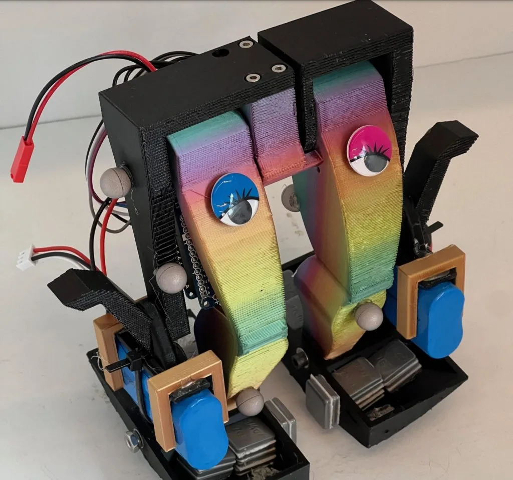
This bionic hand responds to motion control
Reading Time: 2 minutesBuilding a robot is only half the battle, because you also need a way to control it. Something like a rover may work with a simple joystick or even typed commands. But complex robots often have many motors and controlling those all directly becomes a challenge. That’s why Will Cogley chose motion…
-

Make a robot: A fun and educational journey into robotics for kids
Reading Time: 5 minutesLots of kids are excited about robotics, and we have the free resources you need to help your children start making robots. What’s a robot anyway? Did you know that the concept of robotics dates back to ancient Greece, where a mathematician built a self-propelled flying pigeon to understand bird flight? Today,…
-

This gargantuan 3D-printed robot hand is just the beginning
Reading Time: 2 minutesIvan Miranda has a humble dream: he wants to build a massive 3D-printed robot that he can ride upon. In other words, he wants a mech. But that is obviously a very challenging project that will take an incredible amount of time and money. So he decided to test the waters with…
-

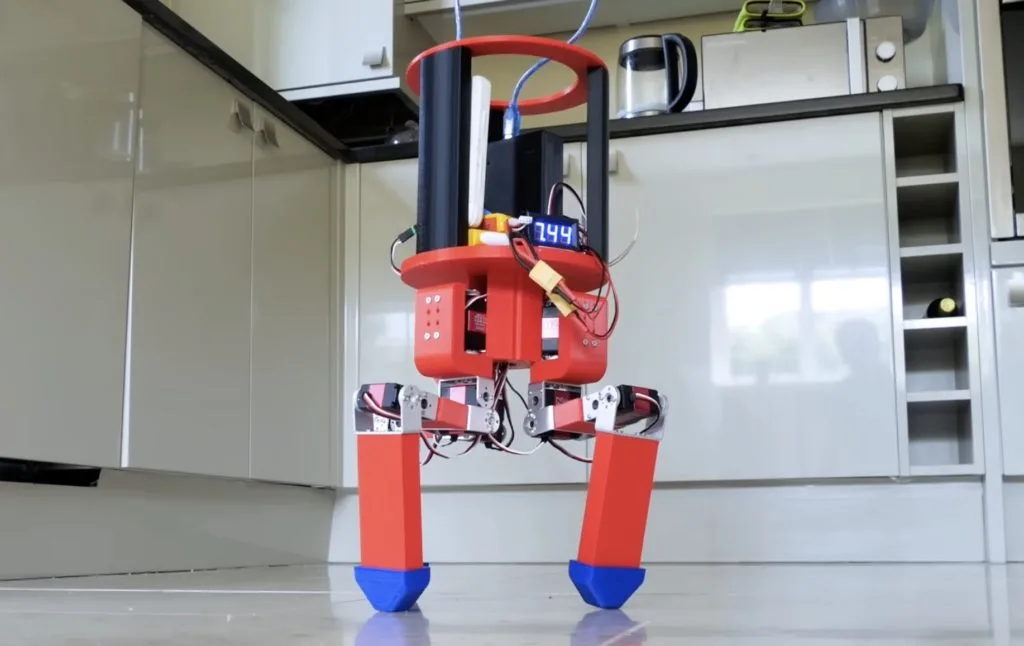
Bipedal robot walks with a single motor
Reading Time: 2 minutesA popular goal among roboticists is animal-like locomotion. Animals move with a fluidity and grace that is very hard to replicate artificially. That goal has led to extremely complex robots that require a multitude of motors and sensors, along with heavy processing, to walk. But even those don’t quite match biological movement.…
-

Helping robot dogs feel through their paws
Reading Time: 2 minutesYour dog has nerve endings covering its entire body, giving it a sense of touch. It can feel the ground through its paws and use that information to gain better traction or detect harmful terrain. For robots to perform as well as their biological counterparts, they need a similar level of sensory…
-

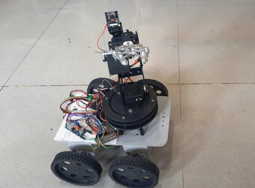
This remote-controlled, highly mobile robot features a 4DOF arm and an onboard camera
Reading Time: 2 minutesStatic manipulators and mobile robot chassis each have their own advantages, and so by combining the two into a single platform, AadhunikLabs was able to realize both at the same time. The base frame is comprised of four individual wheels, each with their own high-torque geared motor and driven by a pair of VNH3ASP30 DC…
-

MiuraKit simplifies pneumatic robot design
Reading Time: 2 minutesSoft robotics is a challenging field, because it comes with all of the difficulties associated with conventional robotics and adds in the complexity of designing non-rigid bodies. That isn’t a trivial thing, as most CAD software doesn’t have the ability to simulate the flexibility of the material. You also have to understand how the…
-

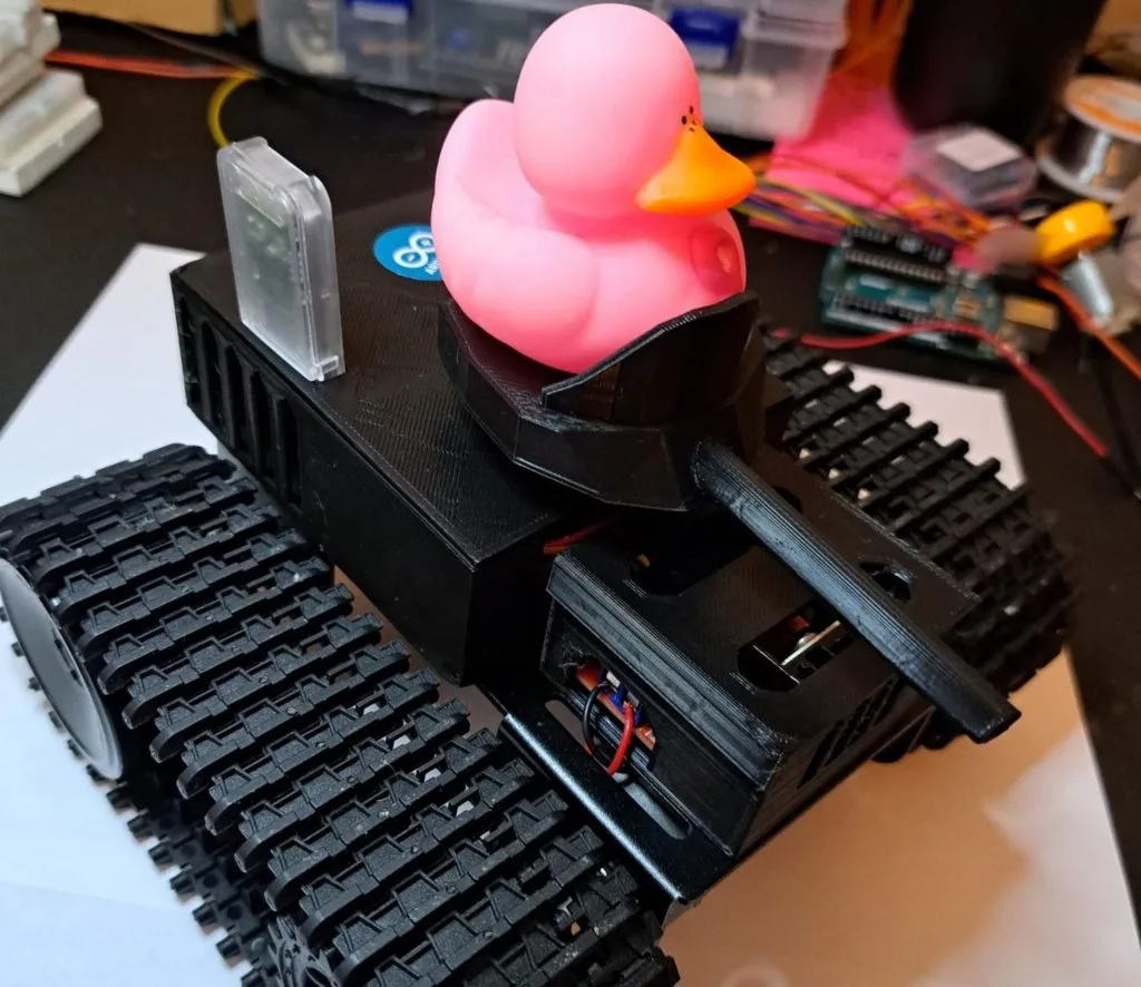
This Bluetooth tank is a perfect first robot
Reading Time: 2 minutesMany kids and adults have an interest in electronics because they want to build robots. But it can be difficult to figure out where to even start. There are hundreds of kits on the market and the options are endless where you veer into custom territory. But if you’re looking for a…
-

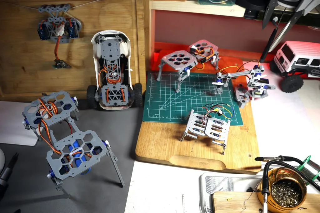
Can tripedal robots actually walk?
Reading Time: 2 minutesBuilding walking robots is difficult, because they either need a lot of legs or some ability to balance through their gait. There is a reason that the robots designed by companies like Boston Dynamics are so impressive. But lots of hobbyists have made bipedal and quadrupedal robots, while largely ignoring tripedal robots.…
-

James Bruton builds a walking AT-AT robot
Reading Time: 2 minutesWas there anything more exciting than watching AT-ATs walk across Hoth towards the Rebel base for the first time? Those massive machines were iconic and helped to solidify The Empire Strikes Back as the best movie set in the Star Wars universe. After experiencing disappointment with AT-AT toys that couldn’t walk, James Bruton built his own…
-

This cheap robot arm can follow recorded movements
Reading Time: 2 minutesThere are many ways to control a robot arm, with the simplest being a sequential list of rotation commands for the motors. But that method is very inefficient when the robot needs to do anything complex in the real world. A more streamlined technique lets the user move the arm as necessary,…
-

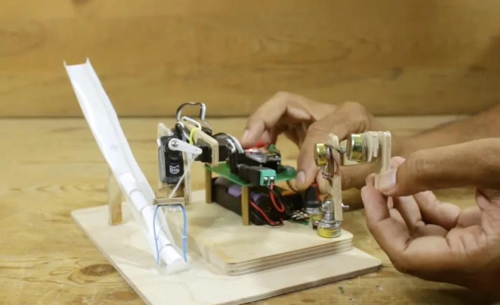
The Whimsy Artist is a little robot that both creates and destroys art
Reading Time: 2 minutesMany people find the subjectivity of art to be frustrating, but that subjectivity is what makes art interesting. Banksy’s self-shredding art piece is a great example of this. The original painting sold at auction for $1.4 million—and then it shredded itself in front of everyone. That increased its value and the now-shredded…
-

Bolt Bots are perfect for aspiring roboticists
Reading Time: 2 minutesWhile it is easier now than ever before, getting into robotics is still daunting. In the past, aspiring roboticists were limited by budget and inaccessible technology. But today the challenge is an overwhelming abundance of different options. It is hard to know where to start, which is why Saul designed a set…
-

TactorBots is a complete toolkit for robotic touch
Reading Time: 2 minutesSo much of the research and development in the area of haptic feedback focuses on universal devices that can create a wide range of tactile sensations. But that has proven to be a massive challenge, as it is very difficult to package the number of actuators necessary for that flexibility in a…
-

Build your own high-quality ARCTOS robot arm
Reading Time: 2 minutesIf you want a robot arm, either for some practical job or just fun, you have a lot of options. There are many consumer and industrial robot arms on the market, but the models that aren’t glorified toys tend to be pricey. You can also build your own. If you go that…
-

Stewart platforms actuate Doc Ock tentacle
Reading Time: 2 minutesOctopus tentacles are, essentially, long continuous muscles — a bit like your tongue. That anatomy gives octopuses incredible dexterity, but it is very difficult to replicate in robots. Artificial “muscle” fiber isn’t very practical yet, which is why roboticists turn to more conventional means of actuation. Cable-driven tentacles are popular, but they…