The challenge
Pest monitoring is essential for the proper management of any vineyard as it allows for the early detection and management of any potential pest infestations. By regularly monitoring the vineyard, growers can identify pests at early stages and take action to prevent further damage. Monitoring can also provide valuable data on pest behaviour, seasonality, and population size. This information can be used to adjust management strategies and protect the quality of grapes harvested from the vineyard.
One of the most effective ways to monitor pests is with pheromone traps. Pheromone traps use synthetic hormone-like compounds to attract specific insects and correctly estimate their overall presence based on their number, preventing major damage and disease to the plants. Using pheromone traps can help protect vines from serious infestations, reduce pesticide use, and ensure a healthy crop. Additionally, these traps can be used to track the activity of a particular species over time which is useful for predicting when pest populations are likely to peak or decline. By knowing when insect pressure is high or low, winemakers can better plan for treatments and cultivate their land accordingly.
The value of conservation and pest control initiatives is immeasurable as the effects of climate change, biodiversity loss, and species invasions become more evident. Traps are widely used for population detection, tracking progress on projects, determining management solutions; in addition to assessing treatment performance.
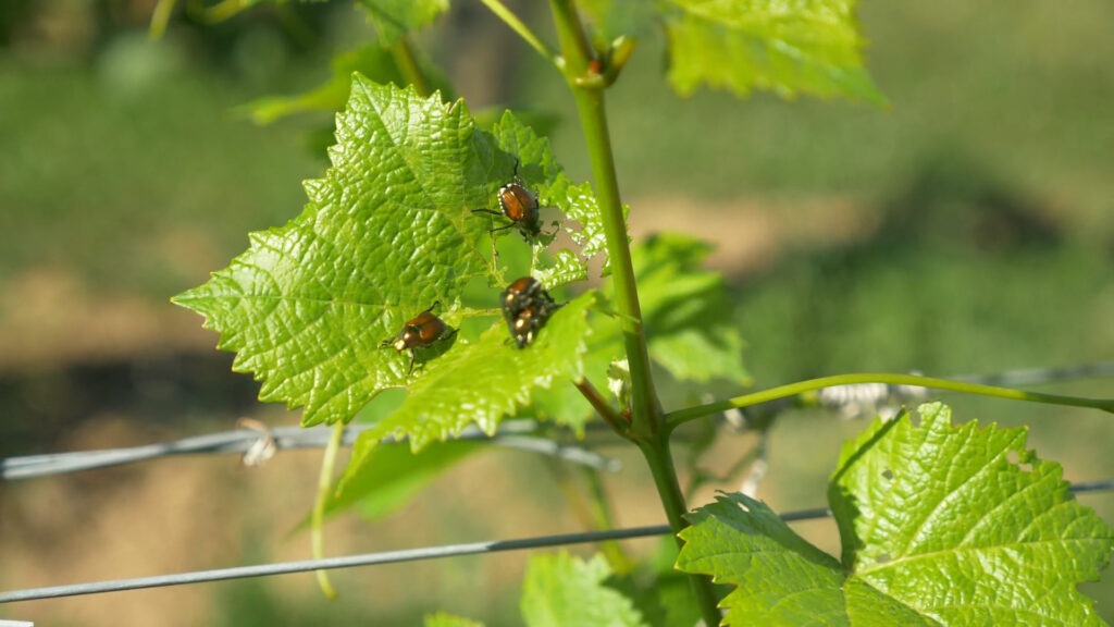
Vineyard Pest Monitoring is the practice of monitoring and controlling vineyard pests, such as Popillia japonica. Popillia japonica is a species of scarab beetle native to Japan that feeds on grapevine leaves and can cause significant damage in vineyards. Traditional pest management techniques involve manual monitoring with traps or pheromone traps. These methods are labor-intensive and may not provide accurate and timely monitoring or pest control.
Our solution
We propose a solution for estimating Popillia japonica populations in vineyards using pheromone traps and Computer Vision.
This system utilizes LoRa® technology to enable remote monitoring of Popillia japonica in vineyards. Arduino Pro allows farmers to monitor Popillia japonica activity with pheromone traps and collect the data remotely. This makes it easier for farmers to detect infestations early and take action, leading to improved efficiency and higher yields. The IoT technology also helps reduce labor costs associated with manual monitoring.
By using Computer Vision in combination with LoRa® technology, real-time data of pest activity can be collected. This information allows growers to better understand the dynamics of Vineyard pests such as Popillia japonica, helping them to make more informed decisions and reduce their environmental impact. With the right monitoring tools, vineyards can now be better prepared to face the increased risk of Japanese beetle outbreaks posed by climate change. With IoT devices, there is no longer any excuse not to employ pest monitoring in vineyards. The use of IoT-based pest monitoring is not only cost-effective, but also helps to reduce the environmental impact of pesticide applications. This makes it an important tool for vineyard managers looking to protect their crops in an ever-changing environment. The future of vineyard management lies in the hands of innovative technologies like this one, enabling farmers to ensure their crops are healthy and safe. By taking advantage of the latest technologies, vineyard managers can make sure their crops are protected from infestations and ensure a successful harvest season year after year.
To address the challenge we will devise a pest monitoring system based on sensor nodes that monitor areas in the vineyard and send the collected data to a LoRa® gateway that can either display it locally or push it toward a cloud solution where further computation can be done. Either at the gateway level or in the cloud, alerts can be set based on certain thresholds considered relevant.
Bug counting
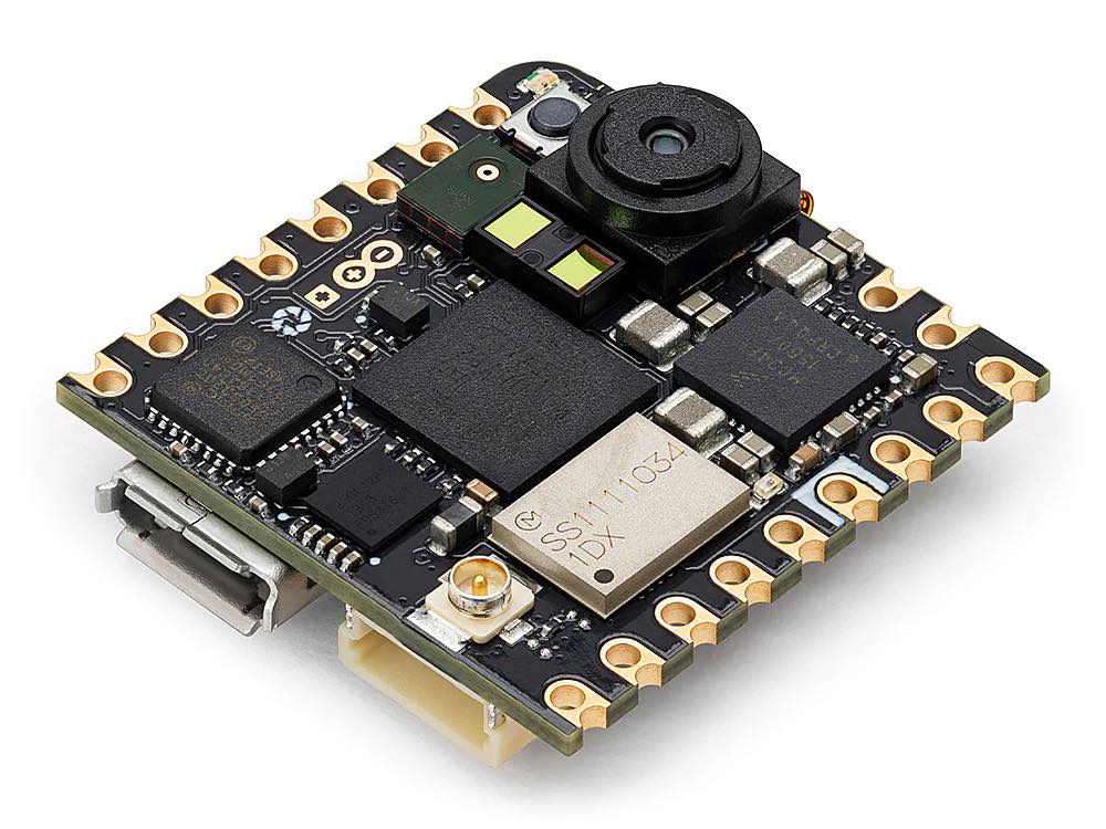
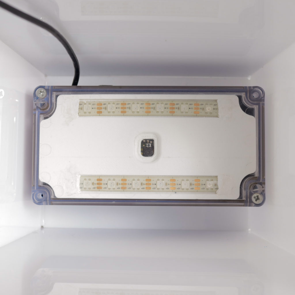
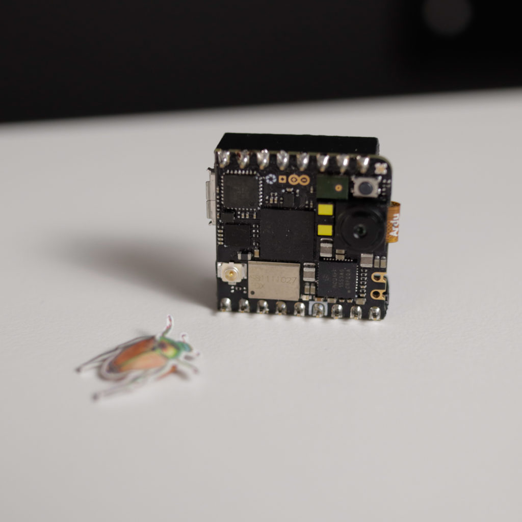
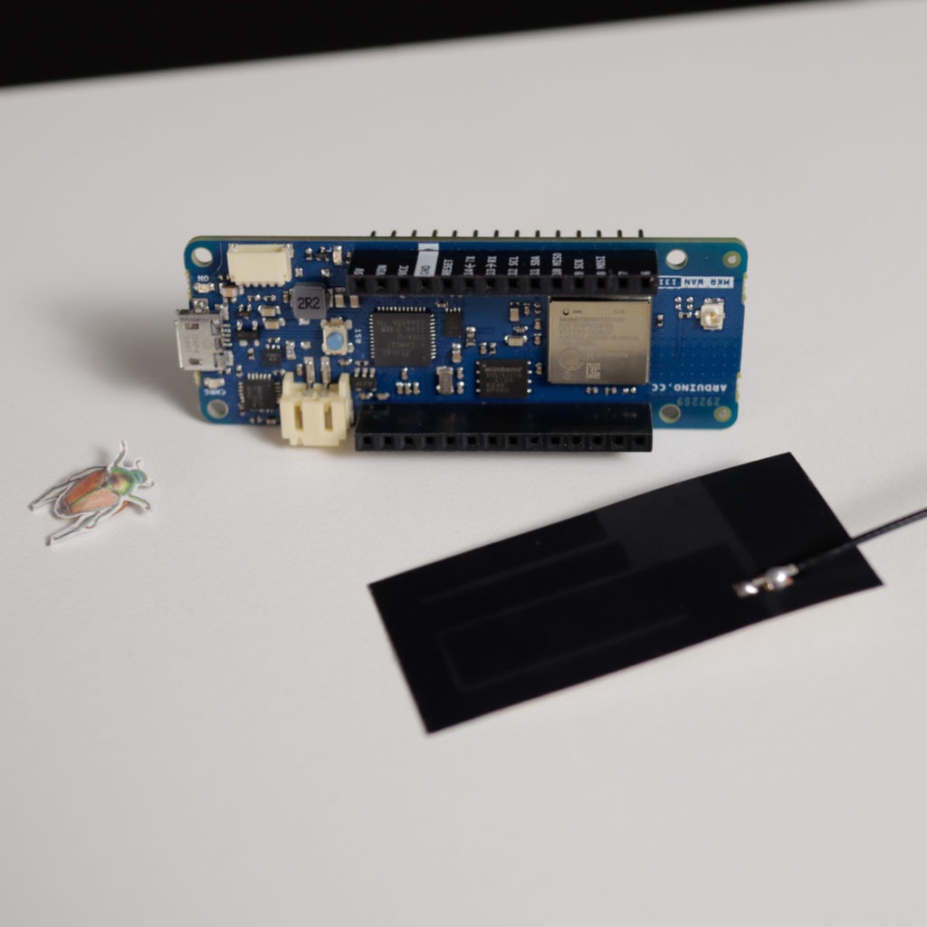
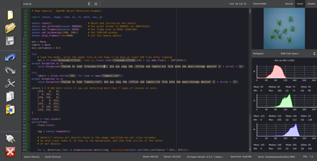
For monitoring the number of Popillia Japonica in each section of the vineyard we have chosen the Arduino Nicla Vision which is ideal for this project because of its advanced image processing capabilities. It combines a powerful Dual ARM® Cortex® M7/M4 IC processor with a 2MP color camera that supports TinyML in a compact format. The full datasheet is available here. For training the object detection model, we have chosen the Edge Impulse platform where we can easily train and deploy a model that will allow us to detect the number of bugs in the view of the camera. After the deployment, no further need of internet connectivity is needed for the camera and only the number of bugs will be relayed to the Arduino MKR WAN 1310 through UART.
Connectivity
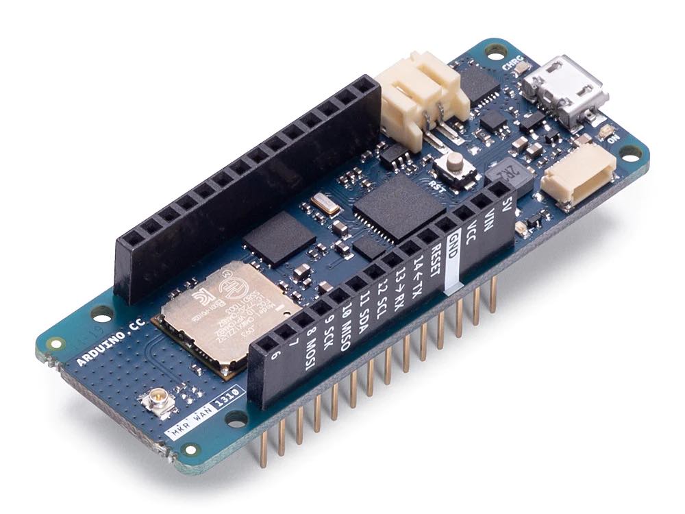
The Arduino MKR WAN 1310 is a powerful and versatile IoT development board based on the ARM Cortex®-M0+ 32-bit processor, perfect for building connected projects. It supports the LoRa® communication protocol, making it suitable for long-range applications such as vineyard pest monitoring. Moreover, it also supports the UART, I2C, and SPI communication protocols so it can easily be interfaced with other devices. Additionally, the MKR WAN 1310 features an integrated LiPo battery charger to keep your project running 24/7. With its compact size and low energy consumption, this board can be used in a wide range of projects where connectivity is required without sacrificing power efficiency.
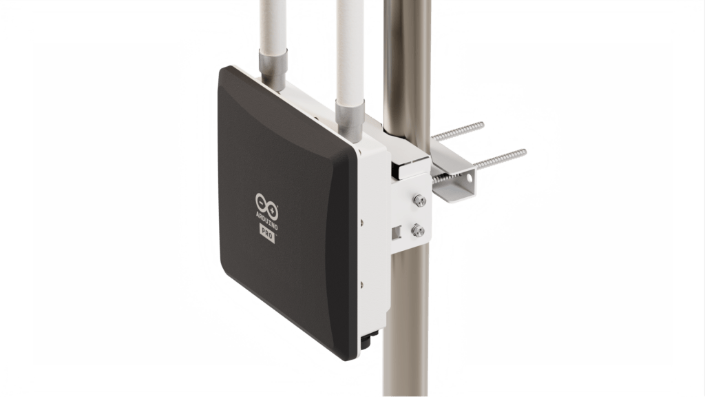
Thanks to its radio connectivity via LoRa® radio transceivers, the data can be sent directly to the nearest LoRa® gateway which forwards it to the Arduino IoT Cloud. The gateway, Arduino Pro WisGate Edge Pro powered by RAKwireless ensures secure and reliable connectivity for a wide range of professional applications and is suitable for medium-sized to wide area coverage in industrial environments and remote regions. Its high transmission power and 2x fiberglass antennas with 5dBi gain provide extensive coverage in open environments, making it the perfect fit for IoT commercial outdoor deployment – required for example for parking sensors, remote fleet management, livestock tracking and geofencing, and soil monitoring solutions that maximize crops’ yield.
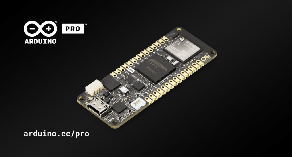
Solving it with Arduino Pro
Now let’s explore how we could put all of this together and what we would need for deployment both in terms of hardware and software stack. The Arduino Pro ecosystem is the latest generation of Arduino solutions bringing users the simplicity of integration and scalable, secure, professionally supported services.
Hardware requirements
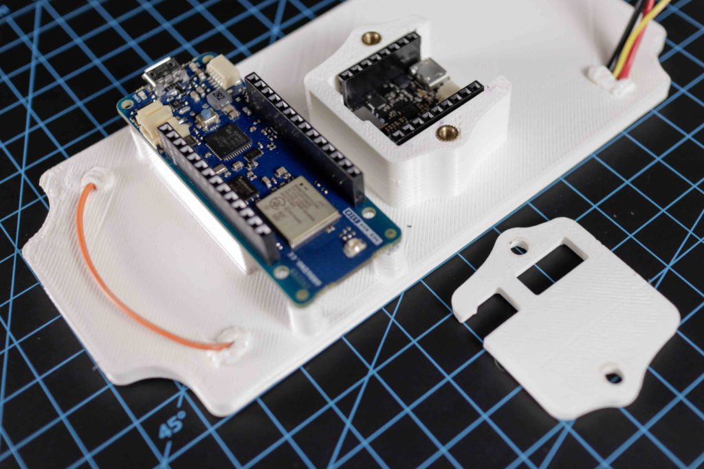
- Arduino Nicla Vision
- Arduino MKR WAN 1310
- Antenna
- WisGate Edge PRO
- White LED Strip
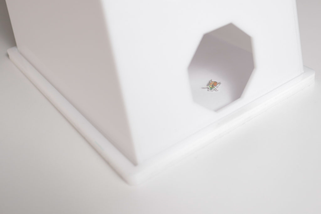
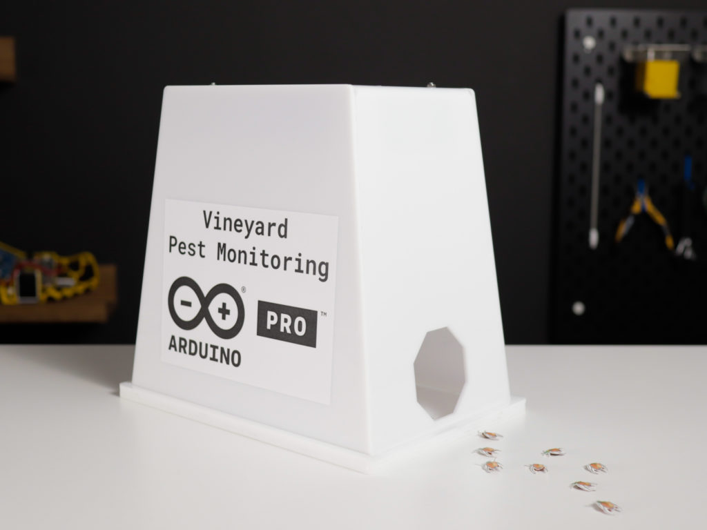
- Enclosures
Software requirements
- Arduino IDE
- OpenMV IDE
- Edge Impulse account
- Arduino Cloud account
- Arduino Create Agent
- The Things Stack account
The Nicla Vision has been programmed in MicroPython since the Edge Impulse model was created/tested using the OpenMV IDE and thus we have also sent the number of detected bugs to the Arduino MKR WAN 1310 via UART.
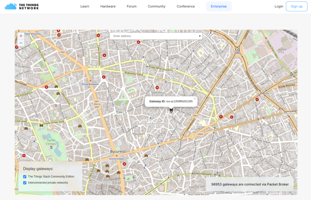
The Arduino MKR WAN 1310 has been programmed in C/C++ using the Arduino IDE and the Arduino IoT Cloud and registered on the The Things Stack (TTS) platform. The Arduino MKR WAN 1310 acts as an end device programmed to receive the number of detected Popilia Japonica bugs from the Nicla Vision through UART and forward it to the Arduino IoT Cloud through the nearest LoRa® gateway connected to the TTS service.
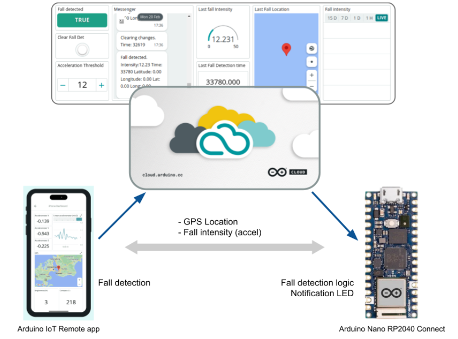
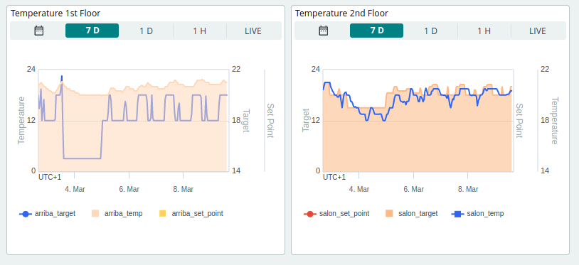
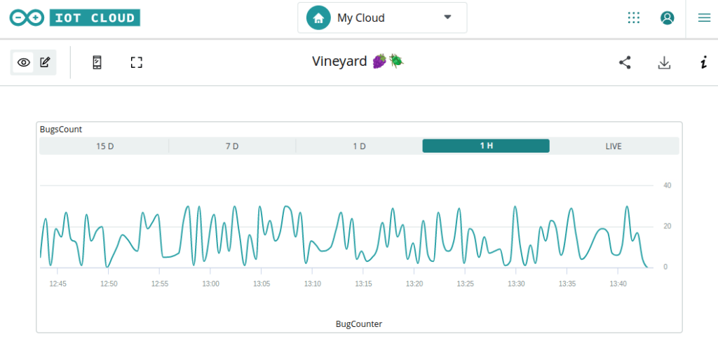
Here is a screenshot from a dashboard created directly in the Arduino IoT Cloud showcasing data received from the sensor nodes:
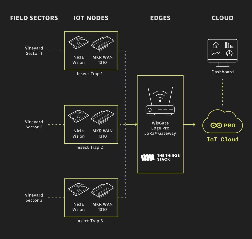
Here is an overview of the software stack and how a minimum deployment with one of each hardware module communicates to fulfill the proposed solution:
Conclusion
By combining Computer Vision with LoRa® technology, farmers can create a reliable vineyard pest monitoring system that is capable of estimating the population of Popillia japonica quickly and accurately. With this IoT-based op-solution, farmers can monitor Popillia japonica activity in their vineyard and take action before Popillia japonica causes significant damage. This helps protect the vineyard from Popillia japonica infestations and ensures higher yields for the farmer. With Vineyard Pest Monitoring with Arduino Pro, farmers no longer need to rely on labor-intensive manual methods for Popillia japonica monitoring. Instead, they can use IoT technology to create an efficient and cost-effective pest monitoring system that provides accurate data about Popillia japonica activity in their vineyards.
In summary, pheromone traps are an important tool for protecting vineyards from pests and ensuring a healthy harvest season and great wines. Salute!
The post Vineyard pest monitoring with Arduino Pro appeared first on Arduino Blog.
Website: LINK