Save 37% off the cover price with a subscription to The MagPi magazine. Try three issues for just £5, then pay £25 every six issues. You’ll save money and get a regular supply of in-depth reviews, features, guides and other PC enthusiast goodness delivered directly to your door every month.
Schlagwort: raspi
-

Win! One of five Raspberry Pi 4 and case bundles!
Reading Time: < 1 minuteSave 37% off the cover price with a subscription to The MagPi magazine. Try three issues for just £5, then pay £25 every six issues. You’ll save money and get a regular supply of in-depth reviews, features, guides and other PC enthusiast goodness delivered directly to your door every month.
-

10 Best Christmas projects
Reading Time: 3 minutesVR to RL
Minecraft can be hacked with a bit of code so that you can make it do as you wish. But this also means that, via more code, it can interact with reality. David Stevens made it so changes to the Christmas tree in the game alter the lights outside. Clever!

Advanced tree lights
We quite like the smart lights we made ourselves, but if you want to do some serious Christmas tree hacking, we suggest taking a look at this amazing project on Instructables.
Upgrade your office
If you find fishing names out of a hat a bit old-fashioned, you can always have Babbage Bear choose for you. Squeeze his hand and he’ll print out a piece of paper showing who you need to buy for. There’s a £5 gift limit, though.
Home light automation
This is a serious amount of lights all over this house to be controlled by a Raspberry Pi. David does so using a phone to connect to Raspbian via VNC.
Raspberry Pi fireplace
Some people like to turn on the fireplace video on Netflix; others prefer to create digital fires of their own. This one also does the impossible and can cycle through different colours of flame.
Make a list
A modern take on the palm readers you used to find on seaside piers, although this machine takes a more binary approach: are you naughty… or nice? Think happy thoughts.
Drop the house bass
Another project where a house has been kitted out with full Raspberry Pi-powered lights – only this one plays music and syncs to it as well. Especially phat dubstep tracks.
Catch Saint Nick
This is a fun Scratch project that allows you to go to sleep happy in the knowledge that you won’t miss Santa. Maybe you’ll find out exactly how big his sack of toys is.
Hack the magazine
A couple years ago we made a little project that allowed you to turn a copy of The MagPi into a light-up Christmas card. Grab the PDF, print the cover on card, and give it a go!
Send us your holiday projects
Made something with Raspberry Pi for this holiday season? Send us photos on Twitter (@TheMagPi) or via email and we might feature you in the next issue!
-

Hack GraviTrax with Raspberry Pi
Reading Time: 7 minutesWhen you get your starter set, you have to prepare the cardboard base by pushing out hexagons to leave holes to mount the tiles in. Do not discard these hexagons, because we are going to use them in our project. If you have already discarded them, then you’ll need to cut out a hexagon from either cardboard of the same thickness or 3 mm plywood. We made two types of sensor: a standalone one, and ones where you have to modify an existing part. Just like the GraviTrax system, our approach is modular and you can make as many of each sensor type as you like.
How does this Gravitrax hack work?
All the sensors in this part use light to detect the presence of a ball – through breaking a beam, detecting reflected light, or simply the presence or absence of ambient light. As such, the circuits are all very similar as shown in Figure 1; the only difference is the physical sensor used, and the current limiting resistor value on the LED. They are connected to the Raspberry Pi by a length of three-wires-wide ribbon cable, with a pull-up resistor going on the board that connects to the GPIO pins. In later parts of this tutorial series, we will look at making a distribution board for them all.
Optical slot sensor
The first sensor we will look at is an optical slot sensor. This fits under a track and the height can be adjusted by using the small or large height tiles. Basically, this is a cardboard hexagon with a small piece of 3 mm plywood stuck on it and the electronics glued to that, going from point to opposite point on the hexagon. The physical construction of the electronics board is shown in Figure 2, with the whole assembly shown in Figure 3. It is best to glue the electronics in place with a track running through it, between two pieces, so you can get it aligned precisely.
Reflective detector
The previous sensor needs to be placed under a track, whereas this one can be placed in an adjacent space and it looks downwards. It is capable of detecting balls on the entrance or exit to any of the tiles, be it basic, curved, or launch pad. The sensor is easy to make, as the LED and transistor symbols are drawn on the part. We used a stack of five cardboard hexagons glued together, followed by a plywood hexagon with a hole in the centre and a 10 mm, M3 countersunk screw sticking through it. This was then placed on the arm, and could be rotated to the required point.
Making the reflective detector
Figure 4 shows the measurements of the plywood arm, and the mounting bracket made from a piece of 12×12 mm angle aluminium. The arm should be notched with the corner of a square file; this is so a cable tie can grip the ribbon cable without slipping. The height of the sensor is adjustable due to a long slot in it, allowing it to be slid up and down. You need a gap of about 2 mm between the sensor and the top of a ball to detect it reliably (Figure 5). You can mount two arms on a stack to get coverage of another position.
A track monitor
The last two sensors have been standalone; the next one modifies a GraviTrax part. The physical layout is shown in Figure 6. The TCRT1010 sensor comes with bent leads which neatly wrap round two holes of stripboard. On the strip side, you need to bend the connectors over again and cut them short. Then bend the middle two so they sit on one track and solder them up. You also need a surface-mount 51Ω resistor to make it small, although a 025 W through-hole resistor could be used. The assembly needs hot-melt gluing onto the track (Figure 7).
Launch pad monitor
Take an OPB706B sensor and wrap it round the centre post in the launch pad tile (Figure 8). Push it down and use a pencil to mark the outline on the wall. Then, using a Dremel, and 1 mm router bit, cut to about 1 mm short of the outline you drew, so the part does not go through the hole. Also, cut a slot in the opposite side to let the wires through when attached to a height tile. Paint black the area the sensor is pointing at, and glue a 10×2 mm piece of 1 mm thick styrene to the green plunger with polystyrene glue (Figure 9).
Switch monitor
This uses ambient light to detect which way the switch is set. Draw in pencil around the switching lever in both positions, showing the area being covered and uncovered. Then drill a 2 mm hole in the middle of this area (Figure 10). Next, paint the underside of the switch tile black, and make sure you paint on the inside of the hole (Figure 11). The schematic of this sensor is somewhat different from the others and is shown in Figure 12. Finally, Figure 13 shows the physical layout of the parts. Position the board so you can see the white sensor through the hole and fix with Sugru.
Software to control the hacked GraviTrax
We have written software, shown in the sound_trigger.py listing, that monitors these sensors, and triggers sounds, either immediately or after a delay.
Click here to visit the Pi Bakery GitHub page and download the code.
The software is modular: line 82 determines what GPIO pins you will use and it automatically generates a window size to accommodate the number of pins in this list. Note if you want to use GPIO 14, you should disable SPI before booting with the sensor attached. The sounds’ names are in a list at line 88; by simply changing or adding to this list, different sounds can be used. The GPIO pins are scanned and when a trigger condition is met, the event is put in a pending list to be actioned at the correct time.
Using the software
The user interface is shown in Figure 14. For each line, you can set what the trigger action will be. These states are: disabled, when the signal goes high, when it goes low, or when it goes either high or low. They are changed by clicking on the trigger icon. The delay column, as you might expect, determines a delay between the trigger and the sound, whereas the sound sample played can be changed by the icons on the right. You can change the GPIO pin and note that one pin can trigger different actions; so, for example, you could have the switch tile generating a different sound depending if it is changed to the left or right.
Choosing sounds
We found short sounds were generally best, but longer sounds can be useful at the beginning or end of your run. We copied a lot of sounds from the Scratch media library from the path /usr/share/scratch/Media/Sounds into our sounds directory. Make sure that are all .wav files, because that suffix gets added automatically to the file names. Note that the slot sensor will read as a logic zero with no ball, whereas a reflective sensor will read high in the absence of a ball. There are lots of suitable sounds available online as well.
We have looked at adding optical sensors to detect where a ball is, be it on a track or a tile. Next month we will look at how to add different sorts of LED displays to enhance your GraviTrax layout. In the meantime, if GraviTrax is new to you, then have a play with the different layouts in the accompanying booklet.
Tip! Track monitor
When gluing the PCB to the track, glue the long edge first, then push the sensor slightly so it is not parallel to the track, and test that it detects the ball before gluing the sides to hold it into position.
-

Code the Classics now shipping
Reading Time: 2 minutesAnnounced on the Raspberry Pi blog a couple of weeks ago, Code the Classics has been available for pre-order and is eagerly awaited by Raspberry Pi fans around the world.
The book is now shipping. If you pre-ordered a copy, it’ll be winging its way to you today, and you can still buy a copy of Code the Classics, for £12, from the Raspberry Pi Press store – order by 17 December for free UK delivery in time for Christmas. We can also send it to you anywhere in the world.
Code the Classics is 244 pages of video game coding gorgeousness. And you’ll find a homage to these classic video games (along with the code to create your own similar game):
-
Pong
-
Bubble Bobble
-
Centipede
-
Frogger
-
Sensible Soccer
We think it’s a wonderful book. According to our sister magazine, Wireframe:
„This stunning 224-page hardback book not only tells the stories of some of the seminal video games of the 1970s and 1980s, but shows you how to create your own games inspired by them using Python and Pygame Zero, following examples programmed by Raspberry Pi founder Eben Upton.“
Click here to pick up a copy of Code the Classics from the Raspberry Pi press store.
-
-

The Swirl Machine
Reading Time: 4 minutes“The Swirl Machine is an interactive, digital-meets-the-real-world machine that swirls Santa Maria Valley wine and turns it into a digital piece of art,” say the team from KPS3, the marketing agency behind The Swirl Machine.
“It was created and developed by KPS3 for Visit Santa Maria Valley. The machine allows users to select their ‘Fill Level’ and ‘Swirl Speed’. In real-time, the user can watch the glass fill, swirl, and splash the wine onto a piece of paper, creating an original Santa Maria-style spill artwork. Every swirl and spill will be unique to each individual user” say Rob Gaedtke and Jonathan Rutheiser of its marketing agency KPS3.
It’s a bit like a Rube Goldberg device, albeit without the Powerhouse music playing. The result of your swirl is sent to you as a photo, and there’s even a fun personality result that comes with it.
“The idea came on a car ride to Santa Maria Valley,” Rob and Jonathan explain. “The team was playing around with the idea of capturing slow-motion swirls, which led to how interesting wine spills are, and that led to The Swirl Machine. The fact that it was a spill fit perfectly into the vibe of Santa Maria Valley’s wine experience… if you spill a little, no one really cares. And because of who KPS3 is as a company, it clearly had to push technical boundaries.” (KPS3 is an integrated marketing agency that works with companies across the globe to find insights in data and bring them to life.)
Making a splash
At the time of writing, there were around 2000 ‘swirls’ on The Swirl Machine’s website – a machine been made possible thanks to a Raspberry Pi.
“We like Raspberry Pi because it has a very low barrier to entry,” the KPS team says. “For only $35 you get a fully functioning computer with I/O capabilities. The community behind Raspberry Pi is also active and helpful, which means you get software packages that are thoroughly tested and you never spend too much time figuring out solutions to problems.
KPS3 has used Raspberry Pi on many different projects in the past. This includes powering a media server, emulator, live‑streaming client, or The Swirl Machine. They use Raspberry Pi because „it’s more than powerful enough to handle the tasks we’ve thrown at it.”
The machine uses a number of technologies. The website is hosted in AWS (Amazon Web Service). A robot arm grabs paper and moves it along the swirl production line. Arduinos control the wine glass, and a spinning plate swirls the glass. Each piece of wine art is unique, including the corner splash that we managed to make during our go with it.
Warning: Spinning glass
If you choose to recreate this project, please fix glass on a spinning turntable carefully (and at your own risk).
Swirl your style
1. To make your own wine swirls first select how full the wine glass is. This tells the pump how much wine to dispense into the glass. You can also choose the amount of ‘swirl’ for your glass, which sets a target speed for the spinning wine plate.
2. A gripper arm with an air-compressor-powered suction cup grabs your piece of special paper. It brings it to the paper holder, where the paper is then moved into position. Wine is dispensed, the glass is spun, and art happens.
3. A camera records the footage of the swirl, and a different camera takes a picture of the final piece. As the wet paper isn’t perfectly straight, the image is processed to make it look perfect before being shared with the creator.
Quick facts
-
The video of a user’s swirl can be replayed
-
The Swirl-nalysis takes into account the final art and your settings
-
The queue lets you watch the swirls ahead of you
-
More than 1600 people have created about 2000 swirls
-
Art is very cool, however you make it
-
-

Set up a Raspberry Pi retro games console
Reading Time: 8 minutesWhether you are nostalgic for the games of yesteryear or you’re simply dying to discover gaming’s rich history, all you ultimately need to get stuck in is a bunch of emulators and a stack of gaming ROMs.
In the past, however, this has also entailed finding and downloading the BIOSes of various machines and a fair bit of configuration. Fortunately, with the software platform Lakka installed on your Raspberry Pi 4, the path to gaming glory is much smoother these days.
Lakka allows you to emulate arcade games as well as titles originally released on a host of 8-bit, 16-bit, and even 32- and 64-bit systems.
Lakka is a Linux operating system based on RetroArch. Lakka is designed to run games, and it turns a Raspberry Pi into a powerful games system.
You can hook up a gamepad and even make use of wireless controllers (there’s more about those at magpi.cc/HpPSSV). It has an interface that will be very familiar to anyone who has used modern games consoles and because it is open-source, it is constantly being improved.
You can run Lakka on any Raspberry Pi, although Raspberry Pi 4 enables smoother emulation of more recent consoles.
Some features help you organise your growing gaming collection and take screenshots of the in-game action. For now, though, we’re looking solely at getting you up and running with a classic homebrew video game.
Warning: it is illegal to download copyrighted game ROMs from the internet. Please respect the original maker and seek a legal source for retro gaming instead. We use homebrew ROMs made by modern makers for classic systems.
Get SD Card Formatter
We’re going to install Lakka RPI4 to a blank microSD card using the OS installer NOOBS (magpi.cc/noobs).
In this tutorial, we’re using a Windows PC to format a microSD card and copy the NOOBS files to the card (the process is identical for Mac computers). We will then use the NOOBS card with our Raspberry Pi 4 and set up Lakka. From then on, our Raspberry Pi 4 will boot straight to Lakka and let us run games.
First, download SD Formatter on a computer from magpi.cc/sdcardformatter. Click ‘For Windows’ or ‘For Mac’ depending on your machine.
Format the card
We’re now going to format the microSD card that you will use to boot Lakka on a Raspberry Pi. Note that this completely wipes the card, so make sure it contains nothing you need.
Insert the microSD card into your Windows or Mac computer. You will need to use either a USB SD card adapter or microSD card to SD card adapter.
Close any alert windows that appear, and open the SD Card Formatter app. Accept the terms and conditions and launch the program. On a Windows PC, click Yes to ‘Do you want to allow this app to make changes to your device’ (you won’t see this on a Mac; the approval comes later).
The card should be assigned a letter under Select Card. It is ‘D’ on our system. Check the Capacity and other details to ensure you have the correct card. Now click Format and Yes. On a Mac, you’ll be asked to enter your Admin password.
Download NOOBS
Now visit magpi.cc/downloads and click the NOOBS icon. Select ‘Download ZIP’ next to NOOBS.
The latest version of the NOOBS zip file (currently NOOBS_v3_2_1.zip) will be saved to your Downloads folder.
Extract the files from the NOOBS zip file (right-click and choose Extract All and Extract). Now open the extracted NOOBS folder (it’s important to ensure you are using the extracted files and not looking at the files inside the zip file. Make sure you have opened the NOOBS_v3_2_1 folder and not the NOOBS_v3_2_1.zip file.
You should see three folders – defaults, os, and overlays – followed by many files beginning with ‘bcm2708…’. It is these folders or files you need to copy to the microSD card.
Select all of the files inside the NOOBS folder and copy them to the microSD card. When the files have copied, eject and remove the microSD card from your PC or Mac.
Boot to NOOBS
Now set up your Raspberry Pi 4. You’ll need to connect a USB keyboard and HDMI display for the installation process (you can remove the keyboard later and use just a game controller).
The display does not have to be the television you intend to use. It’s best to use Raspberry Pi 4’s HDMI 0 port. We’re going to use a wireless LAN network to connect to the internet, but you can connect an Ethernet cable attached directly to your modem/router.
Insert the microSD card into your Raspberry Pi and attach the USB-C power supply to power up.
Connect to wireless LAN
The NOOBS screen will appear, displaying two installation options: Raspbian Full and LibreELEC. To get further installation options, you will need to be connected to the internet.
Connect Raspberry Pi directly to your modem/router using an Ethernet cable; or click the ‘Wifi networks (w)’ icon. The WiFi network selection window appears; wait until it displays the local networks. Select your wireless network and enter the password for it in the Password field. Then click OK.
With Raspberry Pi connected to a network, you get a much broader range of installation options. Near the bottom will be Lakka_RPi4.
Use the arrow keys on your keyboard to select Lakka and press the SPACE bar to add a cross to its selection box (or use a connected mouse to select the Lakka option).
Click Install and answer Yes to the Confirm window. NOOBS will download and extract the Lakka file system to the microSD card. Sit back and wait for the system to be installed.
When it has finished, NOOBS will display ‘OS(es) Installed Successfully’. Press ENTER on the keyboard (or click OK with the mouse).
Starting Lakka
Raspberry Pi will restart and this time it will boot into the Lakka operating system. You will see a blue screen with a series of windows and ‘Load Core’ will be highlighted. You can use the arrow keys on the keyboard to navigate the menu, and X to select a menu option, then Z to back up.
Highlight Load Core and press X to select it. Here you will find a list of ‘cores’. These are the engines that emulate different retro consoles and computers.
To test the system is working, highlight 2048 and press X again. You’ll be returned to the main menu, but this time you’ll see ‘Start Core’. Press X to start the core and you’ll be presented with a classic game called 2048. Use the arrow keys to slide the blocks together. Matching numbers double in size, and the aim is to make a 2048 block. Press ESC and ESC again to return to the main Lakka menu.
Connect to the network
You need to connect Lakka to the network. Use your cursor keys to navigate Lakka’s menus, and head to the Settings list. Press the down arrow and select ‘Wi-Fi’. Wait for Lakka to scan the local networks.
Select your wireless LAN network and use the keyboard to enter the Passphrase. The Lakka interface will display the name of your wireless network with ‘Online’ next to it.
Get a game
Now it’s time to find and play a game. Games are downloaded as ROM files and added to Lakka. These ROM files need a compatible core to run (most but not all ROM files will run correctly).
We’ll use a Japanese homebrew ROM called Blade Buster. Download it on your PC or Mac from magpi.cc/bladebuster – click the ‘Blade Buster Download’ link.
A file called BB_20120301.zip will appear in your Downloads folder. Unlike NOOBS, you do not extract the contents of this file – ROMs are run as compressed zip files. You now need to transfer this file from your computer to your Raspberry Pi.
Turn on Samba
With your Raspberry Pi and PC on the same network, go to the Settings menu in Lakka on your Raspberry Pi and select Services. Highlight Samba and turn it on by pressing X (or using right arrow).
Samba is installed by default on macOS and used to be installed by default in Windows, but it has recently become an optional installation.
In Windows 10, click on the Search bar and type ‘Control Panel’. Click on Control Panel in the search results. Now click ‘Programs’ and ‘Turn Windows features on or off’. Scroll down to find ‘SMB 1.0/CIFS File Sharing Support’ and click the ‘+’ expand icon to reveal its options. Place a check in the box marked ‘SMB 1.0/CIFS Client’. Click OK. This will enable Samba client support on your Windows 10 PC so it can access Raspberry Pi.
Transfer the ROM
Lakka may appear in the left-hand column of your other computer’s file browser (File Explorer on a PC or Finder on a Mac). If not, select Lakka’s main menu on your Raspberry Pi, then choose Information and Network Information.
Take note of the IP address. Enter that into the File Explorer using the format: \\insert.full.ip.address\
Ours, for example, is: \\192.168.0.13\
Copy the Blade Buster zipped game to the ROMS folder on Lakka.
Back on your Raspberry Pi, go to Load Content > Start Directory in the Lakka menu and find the BB_20120301.zip file. Click it before selecting Load Archive. Choose FCEUmm as the core to play it on.
Press ENTER to start the game. Use the arrow keys to move and X to fire. Enjoy playing the game. Press ESC twice when you’re done, to return to Lakka.
Top tip: SSH
You can also use SSH to copy files from your computer to Raspberry Pi. In Lakka, enable SSH in Services. You can use a program such as FileZilla to copy files across. See magpi.cc/ssh for more information.
Set up a controller
Video game consoles rarely come with keyboards. And no doubt you’ll want to attach a controller to your console.
If using a wireless gamepad, insert its dongle into one of Raspberry Pi’s USB ports, insert the batteries, and turn it on. Press the Start button on the gamepad and it will light up.
Use the arrow keys to choose Input and User 1 Binds. If it is connected correctly, you will see ‘RetroPad’ next to User 1 Device Type. Scroll down and choose User 1 Bind All. Follow the on-screen instructions to press the buttons and move the analogue sticks on the gamepad. You may have to go through it a few times to get the process right.
You can also set each button individually using the options. Once everything is set up correctly, you’ll be able to use the gamepad to control your Raspberry Pi console.
Move to the television
Your Raspberry Pi games console is now ready to be moved to your television. You will be able to control the games console using your USB or wireless controller and move ROM files directly to it from your Windows PC or Mac computer.
There’s a lot more to Lakka to discover, but for now we hope you enjoy playing retro games on your Raspberry Pi console. It’s worth heading over the Lakka forums for friendly help and advice: magpi.cc/lakkaforum
-

Learn computing systems with Raspberry Pi
Reading Time: 3 minutesBy Noam Nisan and Shimon Shocken
-
Price: £25/$35
Modern computing systems are built on a stack of technologies. Right at the top, you have the operating system and high-level languages like Python. These sit above a virtual machine that communicates via assembly language to the hardware, which itself is built on a system of chips and logic gates. Head down and you’ll hit physics.
Professional programmers often don’t know what’s going on deep down in the computer system. They rely on the fact that what they do works.
The Elements of Computing Systems is the book behind the more popular Nand to Tetris course (aka ‘nand2tetris’). Using a hardware simulator to build a NAND (NOT-AND) gate, the latter is then used to build all the other chips and gates that form a computer. You then use that to build a general-purpose computer system, called Hack; and a compiler, called Jack. You use these to build an operating system.
The corresponding website (nand2tetris.org) has projects, software installation, and sample programs made with Jack (including the aforementioned Tetris).
By David Wentzlaff
-
Price: free
Princeton University’s Computer Architecture course is on Coursera and is widely regarded as one of the best ‘all-rounders’. The course covers architecture, pipelining, cache, superscalar, and works its way up to multiprocessors.
The course is led by David Wentzlaff, Associate Professor, Electrical Engineering at Princeton, and he leads you through the concepts. By the end of the course, you will have a good understanding of the different types of processor architectures.
You can enrol on the course for free, although there is no certificate for completion.
By Parrot
-
Price: £100 / $130
Computer Organization starts with computer and performance, before moving on to processor unit design and memory system design, then input-output design and pipeline design techniques.
Of particular interest for Raspberry Pi fans is its coverage of RISC – reduced instruction set computers. It’s developed using the GATE (Graduate Aptitude Test in Engineering) syllabus, making it useful for undergraduates. But the course content of use to anybody interested in learning computing architecture.
The price is listed at $132, but it’s frequently on sale (it was $10 at the time we went to press, so look out for that).
More computing books you need
Code: The Hidden Language of Computer Hardware and Software
This book is famous for explaining complex concepts to non-technical people. It doesn’t teach anything about programming, but is a great place for absolute beginners.
But How Do It Know?
This book is designed to bridge the gap between knowing the major parts of a computer and starting a complete course. The first three chapters are available on Google Books (magpi.cc/tQrtY5).
Algorithms to Live By
Learn how computer science can be applied in the real world (and gain a further appreciation for the computing concepts in the meantime).
Websites are also excellent resources for learning about computing. The GeeksforGeeks website should be bookmarked anyway, but take a look at the Computer Organization and Architecture tutorials section.
Stack Exchange has two useful boards for you: Computer Science and Electrical Engineering. Sign up with both.
There are countless CPU simulation programs and sites to explore, many based on the Little Man Computer model. Why not start with this offering?
-
-

Interview with Liz Clark aka Blitz City DIY
Reading Time: 4 minutesNot everyone has been tinkering with electronics for decades. Some are new to the hobby, and it’s easy to figure out why: information on the internet is easier to obtain than ever, and the low cost of Raspberry Pi has helped to further its accessibility. Liz Clark is one of those newcomers. She’s a Vlogger and community YouTube channel owner.
“I actually got a bit of a ‘late’ start to making (although I’m a firm believer that it’s never too late to learn something new),” Liz tells us – and we completely agree.
“I was in college and decided that I should try and learn some coding without really knowing what that meant. I was majoring in music technology, so I began my search in the music arena and learned about Arduino and all of the MIDI projects that people were beginning to make with them. I dabbled a bit off and on with it, but it wasn’t until about four years ago that I really got serious about it and now I’m doing a bit of everything: CircuitPython, 3D printing and design, PCB design, and of course a hearty portion of Raspberry Pi. Outside of hardware, though, I am a long-time avid knitter, cross-stitcher, and sewer.”
We’d also argue that textile arts are a form of making as well, just a bit more low-tech.
Why did you start your channel?
Related to my ‘late’ start in making, I had been out of college for about two years and was starting to feel a little stuck. I really wasn’t working on any creative projects and I was worried that I was going to permanently fall into that rut working full-time. I also have a video background and I hadn’t filmed and edited anything for fun at that point since school, so my channel was basically born from a place of worry and/or quarter-life crisis.
Setting up my YouTube channel Blitz City DIY was a very surreal and odd thing for me to do because I definitely lean more toward the introverted side, so the idea of me talking on camera about things was completely outside of my comfort zone. However, I’ve become a lot better at speaking as a result, and my goal for working on creative projects and keeping up my video skills wouldn’t have been possible without my channel. It’s also led to some really amazing opportunities that otherwise I wouldn’t have had, so I’m so glad I took the initial risk.
When did you first learn about Raspberry Pi?
I first learned about Raspberry Pi a couple of years ago, around the time that I was starting my channel. It honestly seemed a little mysterious to me at first because I wasn’t quite sure what it was or what it did, but I quickly fixed that and fell in love with Linux and all things single-board computers.
Blitz City DIY Raspberry Pi projects
“I rigged up a thermal camera using the AMG8833 thermal camera module from Adafruit. It was before I had a 3D printer, so the housing was in a modified picture frame. That project also ended up becoming my first PCB – I designed up a quick Bonnet-type board to just easily route the thermal camera module to Raspberry Pi’s GPIO.
“I also have an OpenMediaVault instance running on a Raspberry Pi that I use as a home media server and network backup for my computers, and I do run Steam Link on a Raspberry Pi as well. I think that’s one really cool thing about Raspberry Pi in general: you can run a lot of different types of projects on them and there’s always more flavours of Linux becoming available for them too.”
Any future Raspberry Pi plans?
I’m actually working on a big Raspberry Pi project right now. It’s going to be a MIDI-powered robot xylophone. I’m using tiny solenoid motors to strike the keys on a glockenspiel and I’m using MIDI-in over UART (Universal Asynchronous Receiver/Transmitter) on Raspberry Pi. I also made a custom HAT PCB to connect up the MIDI-in circuit and multiplexers to Raspberry Pi’s GPIO. It’s definitely a concept that’s been done before, but having a music background and being a former mallet player, I’m really excited to create my own version.
More inspiring Raspberry Pi makers
Read about more music-based Raspberry Pi makes such as the Perpetual Chimes project, discover some very impressive art project makes and, if you’ve set up your Raspberry Pi as a media server, learn which media player will make the most of your audio collection.
-

Make your own smart Christmas tree lights
Reading Time: 6 minutesChristmas is here, and that means it’s time to decorate. Over the years, we’ve made Christmas tree stars, normal tree lights, and even a light-up card you can make out of the cover of The MagPi issue 52.
This year, we’re heading back to the tree lights to give them an extra ability: voice-controlled lights! We’ll be doing this using a slightly easier method than other audio services, so you won’t need to sign up to an Amazon or Google developer account. Let’s get festive!
You’ll need
The right lights
For our specific build, we’re using 3m of RGB NeoPixels with 30 LEDs per metre. You can find the ones we used here: magpi.cc/iP97nc. These may not be the right lights for you, though. While we think 144 lights per metre is a bit much, the 60 lights per metre version would work well wrapped around a tree or installed on some other furniture. You may also consider getting RGBW LEDs for a brighter (and easier to program) white light effect if you desire.
Install the software
For the voice control and NeoPixels, we need to install a few extra Python libraries to Raspbian. First, install SpeechRecognition by opening the Terminal and typing:
sudo pip3 install SpeechRecognition
Then we need to install PyAudio and a FLAC encoder so that Raspberry Pi can hear what you’re saying and record it. Do it with:
sudo pip3 install pyaudio
sudo apt install flacPlug in a microphone and make sure Raspbian is using it as an input device (you may need to right-click on the volume icon in the top right to do so). Then run the test script:
python3 -m speech_recognition
It will ask you to speak a word and it should return what you said.
Finally, install the NeoPixel libraries with:sudo pip3 install rpi_ws281x adafruit‑circuitpython-neopixel
Top tip: speech-recognition troubleshooting
If you’re having trouble with the test for the SpeechRecognition library, head here to troubleshoot: magpi.cc/RgpLyc.
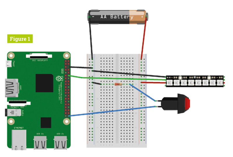
Build the circuit
Build the circuit using the Fritzing diagram as a guide (Figure 1, overleaf). A Raspberry Pi can only power a handful of NeoPixel LEDs safely at a time, which is why you need an external power supply to power the LED strip. Four rechargeable AA batteries will get you the roughly 5 V you need. However, if you have a spare 5 V power supply and a jack to use, that will work just as well, if not better.
The button is installed so we can activate the voice commands – it’s much easier than adding a trigger word like on a home voice assistant.
Test your lights
Once the circuit is all wired up, test your NeoPixels using the neopixel_rpi_simpletest.py script (if you can’t find it on your Raspberry Pi, head here: magpi.cc/Pci4iN).
Change the number of NeoPixels to your requirements and run the script. If the colours seem off, you may need to change the ORDER = line from neopixel.GRB to neopixel.RGB – or neopixel.GRBW or neopixel.RGBW if you have an RGBW strip of NeoPixels.
This is also a good chance to make sure your circuit is properly wired up – check the grounds, the specific GPIO pins used, and whether or not it’s powered properly.
Tweak the code
Download or type out the code listing for this tutorial – smartlights.py. This code was specifically tailored to our build, so you may need to make some changes to the code: specifically, the number of NeoPixels in your circuits, the type of NeoPixels (RGB/GRB/RGBW/GRBW), and the GPIO pins you’re using for the lights and button if you modified our circuit.
Save the file, open up the Terminal, and enter:
sudo nano /etc/profile
Add this line to the end of the file:
sudo python3 /home/pi/smartlights.py &&
This will start the script automatically whenever you turn on your Raspberry Pi.
Explaining speech recognition
The speech recognition part of the code is remarkably simple, and is mostly handled by the speech recognition library. It’s imported as sr in the script, and we use it to listen in on the microphone when required. Once a phrase has been said, it sends an audio file to Google Speech Recognition to be analysed, which is the value variable in our code.
We use this value variable to check against our if statements – you’ll notice we haven’t capitalised ‘lights on’ or ‘lights off’, but we have done for ‘Merry Christmas’ as it returns the value in that way. If you plan to add more phrases, you may need to experiment with them.
Adding trigger phrases
We’ve tried to keep this very simple, including trigger words as part of if statements. To add one, all you need to do is add an extra if statement to the loop. Say you want to add the term ‘happy holidays’, you’d do so like this:
if value == ‚happy holidays‘: strip.fill((255,0,0) strip.show()
In this example, we make the lights turn bright red.
Custom light patterns
The basics of setting LED colours with NeoPixels involves telling the NeoPixels which red, green, and blue (RGB) values to use, from 0 (off) to 255 (maximum). In the previous step, we set red/R to 255 for full red. You can make all three 255 for white. Check out this colour chart to find colour values.
For more complex lights (alternating colours, rainbow effects, etc.) you’ll need to create a specific function that executes the effect. Some of these can be quite complicated, so we suggest checking the examples and docs for the NeoPixel library if you have an idea you’d like to try.
Top tip: RGBW code
With RGB NeoPixels, you only need to program three variables: red, green, and blue. With RGBW ones, you’ll need to add a fourth, e.g. (255,0,255,255).
Install your lights
Once you’ve perfected your lights and voice control, it’s time to put the lights up! We like to wrap ours around the tree, making sure there’s easy access to change any batteries. You may need to add some clips to the tree as well.
If you plan to stick them to other furniture, you may need to make sure you have a temporary solution, like Velcro with sticky backs, so you can easily add and remove them at the start and end of the festive season.
Light up your tree!
It’s time to do the final test of your lights and turn them on! Test out the voice control, and maybe think of moving the microphone position around. With some really long wires, you can also put the button to activate the speech recognition in a place that’s easy to reach.
At the end of the day, you don’t have to turn the lights off, either: you just need to say ‘lights off’.Adding sound and more
One extra feature you might consider is sound output, which can be handled with Pygame. For some voice keywords, you could have lights sync up to classic Christmas songs, carols, or whatever you choose.
We suggest making it so the song only plays through once before going back to normal, though, to avoid incurring the wrath of the people you live with. Last year we create a tree-topper star – you can easily add some NeoPixels to a 3D-printed star like this and have the system control it as well!
Happy Holidays!
We really hope you enjoy making this project and, even if you don’t celebrate Christmas, we hope you think of it as a great introduction to voice control with Python.
From all of us at The MagPi, Happy Holidays and a Happy New Year!PS: don’t forget to share your cool Christmas makes with us on Twitter or Facebook. We might even feature them in The MagPi!
Looking for more projects for the festive season?
How about a GPIO Christmas Tree? Make a Harry Potter fan very happy with this Magic Wand that really makes things move. Entertain the family with this Python-based quiz.
Impress them with this unexpected party popper launcher and by serving up festive cocktails courtesy of your Raspberry Pi butler. -

Astrophotography Autoguider project showcase
Reading Time: 4 minutesCreating stunning photographs of the night sky requires planning, patience, and reliable star-tracking equipment. A desire to travel a little lighter led keen amateur astronomer Joe Kutner to embark on his first Raspberry Pi project.
Joe Kutner (aka Codefinger) is a software architect at Salesforce.com, where he works primarily with Java and other open-source technologies. He’s published several books about programming with Ruby and Java. He enjoys amateur astronomy, mostly observationally, but he also dabbles in astrophotography.
Joe says there’s nothing worse than taking hours of astrophotography images only to find out your telescope was drifting, causing the stars to look more like lines than points. To protect against this kind of misalignment, he needed an autoguider: a computer and camera that track a star in the telescope’s field of view to ensure that it stays in the same position throughout the session.
“The main goal of my project was to get rid of the laptop,” Joe tells us. “I needed to control my telescope in the field. I spend enough time in front of a computer at work, and the laptop took the fun out of observing. It served an important function, though: controlling both my camera and my mount. Without it I would only be able to take very short exposures of the moon and planets.”
Joe considered using an iPad or a Microsoft Surface instead, but both were far too expensive. He wanted to keep the build cost below $100, and neither worked well with his chosen software.
Instead Joe picked up a Raspberry Pi, a case, and a touchscreen for less than $100, and added a red plastic cover so he was still able to use the setup in night-vision mode. These work alongside the various bits of astronomy kit Joe uses regularly on his stargazing missions.
Under open skies
Joe made extensive use of general purpose open-source software such as Raspbian Stretch and Git, plus astronomy-specific open-source tools Libnova, INDI, and PHD2 (openphdguiding.org) telescope guiding software.
He wrote scripts to automate the software so he could just use the touchscreen, without a mouse or keyboard. But for the most part, things worked without customisation.
“Every step in the process had its challenges,” Joe recalls. “I would install one piece of software and then find out it wasn’t compatible with some version of another piece of software I needed. When I finally got everything running, it wouldn’t talk to my telescope until I installed yet another version of the software. There were dozens of these little paper-cuts, but in the end it was worth working through them.”
Joe also says the hardware he chose worked perfectly from day one. Any tweaks he made were “mostly minor issues like figuring out how to install the correct version of a particular camera driver”.
His Raspberry Pi now has an on-board autoguiding system for his astrophotography rig. Because Raspberry Pi attaches to the base of the mount, it’s easily accessible. Unlike using a laptop, there’s no need for an extra table or complicated wiring. Joe says the setup is perfect for his needs: “I can roll my telescope onto my driveway and start imaging in just a few minutes.”
International expansion
Now that Joe has successfully built a fairly portable astrophotography rig, he sees its potential for explorations further afield. He’s keen to try out his autoguider with other types of astrophotography kit such as the ultra-compact Sky-Watcher Star Adventurer series of mounts. “When combined with my Raspberry Pi,” he says, “I could take the whole rig on an airplane as carry-on. That would give me access to some very dark skies.”
Build an autoguider
1. Start with a fresh installation of Raspbian and download the package for libnova 0.14. You can find the install instructions at Joe’s GitHub page.
2. Use the GitHub instructions to build INDI, the software to connect Raspberry Pi to your digital camera and mount. Install the Atik camera driver if needed.
3. Install and build PHD2 autoguiding software, then start the INDI server so it looks for the camera and mount. Save the profile for future reference.
Quick facts
-
Raspberry Pi records over several hours while Joe sleeps in his tent
-
Joe recommends Lacerta MGEN II if you don’t want to build your own autoguider
-
Many of his astronomy photos are taken from home in Huntsville, Alabama
-
He’s using Raspberry Pi to attempt to image an exoplanet transit
-
He also blogs about coders’ fitness and nutrition at healthyprog.com
-
-
GPIO Xmas Tree review
Reading Time: < 1 minuteThe GPIO Xmas Tree is something like that – and probably the easiest one to code yet! It’s also nice and small, sitting over six GPIO pins rather than taking up all 40. This way, you can add a little festive flair to your Raspberry Pi, while still working on other projects that require the use of some GPIO pins.
Easy coding
One of the unique things about this tree is that you can program it with Scratch! Scratch on Raspberry Pi has a built-in GPIO library, allowing you to code physical objects, including this tree’s five LEDs.
This is one of the few cases, though, where something so simple is much easier to do via Python, especially thanks to the GPIO Zero library, requiring less than ten lines of code to create a wonderful twinkling effect!
We quite adore this little tree – it’s cheap and cheerful and could be someone’s first Raspberry Pi project on Christmas morning, with a quick and very cool result.
Verdict
9/10
This fun little project will make your Raspberry Pi work desk festive, or make a young maker’s first steps at Christmas wonderful.
-

Retro computing with Raspberry Pi 4 in The MagPi issue 88
Reading Time: 3 minutesPJ Evans shows you how to put a Raspberry Pi inside an old ZX Spectrum+ computer, hooking it up to the innards. Discover how to connect a Raspberry Pi GPIO pins to the keyboard of a classic machine and use it to emulate the original computer.
Plus! Discover where to find classic games and the best accessories for retro computing fans.
Click here to buy The MagPi magazine issue #88
Thermal testing Raspberry Pi 4
Raspberry Pi 4 runs faster than any other Raspberry Pi computer. The Raspberry Pi team has been hard at work bringing the temperature down, and keeping the speed up. In this in-depth feature, we heat- and speed-test each Raspberry Pi 4 firmware update, and see how they are keeping the temperature down. It’s a wonderful feature packed with information on how the Raspberry Pi works, and has insider information on heat clocking. We even have a rare interview with Tim Gover, the software engineer at Raspberry Pi responsible for firmware, power management, and displays.
Astrophotography Autoguider
We have the best projects in Raspberry Pi, like this astrophotography kit made by Joe Kutner in Alabama. With it, Joe has been capturing the night sky with stunning results.
Make a smart Christmas tree
It’s Christmas! Or at it least it will be very shortly. If you’re getting the tree out, putting up the tinsel, and tasting the chocolate, then why not use Raspberry Pi to create smart lighting? Our very own Rob Zwetsloot explains how to add voice activation to your Christmas tree lights.
The top 10 Christmas projects
Christmas is a great time to be a Raspberry Pi fan, and many a maker has built glittering, all-singing and dancing projects for the festive period. From smart gingerbread houses to massive outdoor light displays, we look at the 10 best Christmas projects.
Community interview: Liz Clark aka Blitz City DIY
Liz has only been making Raspberry Pi projects since 2016, but she has created some stunning builds. On her YouTube channel you’ll find teardowns, 3D printer projects, CircuitPython projects, and quirky DIY builds. Liz’s tale is an inspiration to anybody who feels late to the party. You can always make up for it with interesting makes.
Plus! Win a PiArm Robot Arm Kit
The MagPi is available as a free digital download, or you can purchase a print edition online or in stores.
-
Win a PiArm robot arm kit!
Reading Time: < 1 minuteSave 37% off the cover price with a subscription to The MagPi magazine. Try three issues for just £5, then pay £25 every six issues. You’ll save money and get a regular supply of in-depth reviews, features, guides and other PC enthusiast goodness delivered directly to your door every month.
-

DNA Gel Imager project showcase
Reading Time: 5 minutesResearch labs and hospitals use multimillion-pound equipment for detailed DNA tests, but when part of the kit goes wrong, a low-cost alternative may be urgently needed. Dr Lindsay Clark found herself in exactly this situation when the gel imager she relied on to expose DNA samples broke down.
The machine that broke down was another lab’s imaging equipment, and “carrying somewhat hazardous ethidium bromide gel from place to place” had never been ideal.
While we mainly think of DNA as useful for catching criminals and identifying possible blood relatives using ancestry testing kits, its main use is for genetic research. Cystic fibrosis researchers use it to test for patterns in DNA clusters, for example (see magpi.cc/Cmkj9F).
Dr Lindsay Clark holds a PhD in Genetics. She studies DNA information about plants, animals, and microbes. Her work on plant genetics focuses on environmental and agricultural issues.
In all cases, the DNA material extracted needs to be visualised and, in this case, Lindsay needed her own replacement imager, fast.
As a Raspberry Pi enthusiast, and Python and R programmer, she soon came up with a plan. Lindsay’s interest in Raspberry Pi began when she and her husband wanted a webcam that wouldn’t steal their data. Despite scant knowledge of optics, some online research soon gave her all the details she needed.
Sizing things up
“A typical gel imaging system costs tens of thousands of dollars, but it is essentially a camera mounted over a transilluminator, attached to a computer for taking digital images,” she explains. “We had a transilluminator we’d inherited from an emeritus professor. The only components left then were a camera and a computer, which could be done very cheaply with a Raspberry Pi.” Since Raspberry Pi uses an HDMI output, she also needed an HDMI to DVI converter costing a princely $8.
“We needed to be able to take close-up, reasonably focused images of an orange-fluorescing compound, filtering out other wavelengths of light. The images didn’t need to be publication quality (we could always use another lab’s transilluminator if we really needed to), but they needed to be good enough for us to document approximate DNA fragment sizes.”
Optical collusion
Lindsay first set up her Raspberry Pi 3B camera kit with a fresh Raspbian installation. The only software needed was the standard raspistill command, so she didn’t need to write any custom code. The +2.00 lens used came from an old pair of spectacles. (A stronger lens may have worked even better, she thinks.)
Lindsay then added a lens filter which she bought cheaply online. This was simply to cut out any glare from the transilluminator lamp. The whole setup was housed in a cut-up Styrofoam box. In all, the device cost $150 including the Raspberry Pi 3 and Camera Module, monitor, keyboard, and mouse.
“The biggest challenge was making sure that it could focus on the gel up close,” recalls Lindsay; it can focus from 1 m to infinity. “I tested it out by holding the reading glasses in front of the camera and taking pictures of some flyers.” The imager she’s built can’t zoom or focus but, as she says, “the camera is positioned such that it can get a decent picture of any gel.”
Such has been the project’s success, Lindsay’s colleagues without any Raspberry Pi knowledge have easily made use of it too. She taped instructions on the wall explaining how to trigger the camera using Raspbian, but rarely has anyone asked how to use her DIY setup.
She also encourages others to create their own bespoke equipment. “There’s a great tradition of scientists building their own equipment. Don’t let the existence of a commercial version deter you from building your own!”
Warning
However, Lindsay warns, “Ethidium bromide is a carcinogen, not to mention that a lot of specialised equipment and reagents are needed to get DNA to the point where it could be visualised with my little imager. For example, the most common method of DNA extraction involves using chloroform in a fume hood, and then PCR is typically done after that before visualisation on a gel.”
So the DNA gel imager isn’t something you could easily replicate at home and you should definitely do your research about ethidium bromide. Nonetheless, the idea of using a Raspberry Pi for medical applications has merit.
Making your own imager
1. Set up the Raspberry Pi 3 B Camera Module and install Raspbian. You’ll also need the raspistill command to trigger the Raspberry Pi camera.
2. Cut a hole in the bottom of a Styrofoam box to form an aperture and carve out one seating for the lens filter and a second to hold the glasses lens. Mount the Raspberry Pi camera and secure it in place using paper clips or other adjustable fastening. Lindsay found the gel imager needed to sit 12 inches above the transilluminator, for example.
3. Trace around the camera filter, position one of the lenses in the middle of where the filter was, then trace around the reading glasses. Connect the Raspberry Pi and Camera Module and place the camera over the lens.
Quick facts
-
Lindsay and her husband bought Raspberry Pi boards as anniversary gifts
-
She publishes open-source software for the genetics community
-
She recently built a RetroPie for a friend
-
Lindsay loves solving genetics’ real-world logic problems…
-
such as DNA sequence alignments in allopolyploid organisms!
-
-

UK train departure screen
Reading Time: 4 minutesGiven the time of year, we can perhaps expect some leaves on the line, slippery rain or maybe, if the weather takes a real turn for the worse, the wrong type of snow. But in any case, Chris Hutchinson will be as prepared as any commuter can be thanks to his Raspberry Pi computer.
Chris has had an interest in trains since he was a child and he is the principal engineer at The Times and The Sunday Times newspapers.
The railway enthusiast has developed a miniature real-time train departure board that resembles the ones adorning stations across the world. “I wanted to be aware of any delays or cancellations on the trains before heading out of the house,” he explains. “I knew I could use an app on my phone, but where’s the fun in that?”
At first, Chris took videos of the dot matrix displays at the stations he visited, making a note of the quirks in their displays and paying attention to spacing and the wording they used. “I must have taken videos of 10 or 15 different departure board variations from across the UK,” he tells us. “Based on those, I worked out the minimum dataset I’d need to display the next two services from my local station, and started looking into APIs that provided the data.”
Tunnel vision
Chris decided to use TransportAPI and he soon got down to coding using Python 3. He’s already found the perfect display for the project – a 256×64 SSD1322 OLED screen which he liked because it was affordable, low power, and comes in different colours. “The yellow one looked like a perfect match to the videos I had been taking,” he says. “So I ordered one, excitedly waited for the post every morning and once it arrived, I wired it up, got my code running, and couldn’t believe how brilliant it looked.”
In the meantime, Chris had found an open-source Python library for displaying graphics on OLED screens – one he says is typically used for small animations or displaying debugging data. It also had a software simulator using Pygame under the hood. “It allowed me to test my code before the real screen arrived,” Chris recalls. He’d also stumbled across an open-source set of fonts created by Daniel Hart that replicated real dot matrix departure boards and these only needed some tweaks to their size.
“Most of the heavy lifting is managed in the code and there are two key parts to it,” Chris reveals. “The first is data loading and parsing, making the appropriate network requests for my station and transforming it into a useful data structure. Second is the rendering code where I take the data and turn it into pixels on the screen.”
Now it’s up and running, Chris keeps an eye on the display ahead of his daily London commute: “The board has prevented me from getting stuck out in the rain on more than one occasion.”
On the rails
It also seems to have struck a chord with others. “After I first got it up and running, I shared a video of the build on Twitter and the response was phenomenal. It turns out the crossover between Raspberry Pi and train enthusiasts is pretty significant and there are already a number of forks.“ For example, enthusiasts have expressed a desire to connect the project to bus departure times and non-UK railway networks. „It’s been a real honour to see so many people engage with the product and take it in their own directions“, says Chris.
Quick facts
-
The screen can be bought for about £25
-
Python 3.6+ is needed to run the code
-
TransportAPI has a free tier for makers
-
An API call is made every 1–2 minutes
-
Chris’s boss wants one for The Times office
More Raspberry Pi-based smart tech ideas you could try:
-
-

Cryptography ICE Cube experiment
Reading Time: 4 minutesIn space, nobody can hear you scream, but there are some people who are determined to eavesdrop on communication being sent back and forth between Earth and orbiting satellites. As such, there is a danger that security and safety can become compromised, which is why a team of researchers at the European Space Agency (ESA) have sought to enhance cybersecurity for future space missions.
“There is a risk of satellites being intercepted and hacked, which leaves them susceptible to being controlled by a rogue third party,” explains ESA software product assurance engineer, Emmanuel Lesser. “That presents a big risk for a mission and it’s also a problem commercially since satellites are very expensive and the data that is transmitted is sensitive. It’s important that we protect it.”
Emmanuel’s role at the European Space Agency is to provide software product assurance for the Copernicus Earth observation programme and the Biomass mission.
The right shape
One of the cybersecurity solutions being explored by ESA involves Raspberry Pi Zero, and it is being worked on by a team headed by Emmanuel. Called the Cryptography ICE Cube experiment, or CryptIC for short, the aim is to make encryption-based secure communication feasible for even the smallest of space missions, and it is currently operational in the Columbus space laboratory module of the ISS.
“We wanted the experiment to have a small footprint and a relatively modest energy consumption,” Emmanuel says. “We also wanted to achieve secure communication using the cheapest components. We knew that smaller missions, such as those which use CubeSats [miniaturised satellites for space research], utilise signals that are unencrypted. That leaves them vulnerable, so we looked at the possibilities.”
Since the ICE Cubes facility in Columbus offers plug-and-play installation for cube-sized experiments, the idea was to fit CryptIC into a beige box measuring 10 cm on all sides. “We were able to make use of a Raspberry Pi Zero just as it comes out-of-the-box,” Emmanuel says. “On that is a space-hardened version of Raspbian which has been previously commissioned by ESA. It removes the unnecessary parts of the system so it has fewer libraries, some of which we had to reinstall. But our main task after that was to write the software in Python using some of the existing libraries as well as our own.”
Cryptic clues
The project’s Raspberry Pi Zero also needed to be covered with a plastic ‘conformal’ coating. “This is an ISS requirement and it merely prevents fire hazards – you wouldn’t know it’s there unless you looked really hard,” Emmanuel says. The computer is controlled from a laptop based on Earth at ESA’s ESTEC technical centre in the Netherlands, with data sent back and forth in near real time via the ICE Cubes operator Space Applications Services in Brussels. “We’re not sending any real sensitive data – just strings of ‘hello world’, articles, and images,” Emmanuel continues. It is testing the feasibility of using a backup key that can’t be compromised from the ground, while studying whether microprocessor cores that are based around field-programmable gate arrays are able to offer redundancy if a core is affected by radiation.”
The experiments began to run continuously from September and Emmanuel says the team is looking to stick with a Raspberry Pi Zero in the future too. “Ideally, we’d like to have more RAM and a version without WiFi – we had to buy an older one on eBay because the ISS doesn’t allow WiFi without a special procedure – but it’s near-perfect for what we want,” he concludes.
Quick facts
-
Communication with satellites isn’t always secure
-
CryptIC is a way of boosting mission safety
-
Its form factor is near-identical to CubeSats
-
This is connected to – and powered by – the ISS
-
Its Raspberry Pi Zero is the first in space
-
-

Top 10 AI projects
Reading Time: 4 minutesMachine learning and AI are just a normal part of the world now, which in some ways is kind of hard to process. On the plus side, it means we can have computers do really fun, useful (and useless) stuff for us. Here are ten ways to get your Raspberry Pi to learn and do.
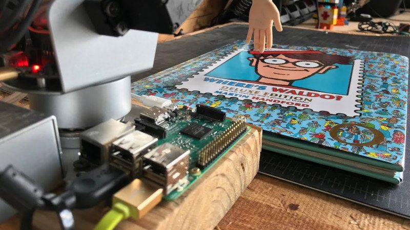
Robot cartoon-hunter
Waldo – or Wally as we call him in the UK – is a very elusive man who likes to travel around the world. The puzzle books asking young folks to find Wally in a busy crowd of people are very popular and can be tricky to solve; that is, unless you’re an AI character hunter.
Self-driving racers
A lot of Raspberry Pi robots aren’t autonomous – the Formula Pi racers are, though: using computer vision and your own bits of code, the aim is to make your robot the fastest and most accurate racer.
Magical item identifier
This project uses Microsoft’s Cognitive Services to look at a picture for identification. When it works, it’s pretty magical; however, it doesn’t always work. Still, it will then use text-to-speech software to tell you what’s in front of you. A future product for blind people, maybe?
Computer chess IRL
The ‘Mechanical Turk’ was a magic trick where chess players would manipulate mechanical arms to make it look like people were facing a machine that could play chess. The Raspberry Turk is no magic trick – it does it for real.
Computer-aided vegetable categorisation
One of the promises of AI is that it can help people out with more mundane parts of work. The cucumber sorter allows a farmer to quickly and efficiently categorise his cucumber harvest. We’ve seen it in action and it is fun.
Self-driving boat
Using GPS and a series of sensors and motor controllers, the Sailbot is one of a few autonomous sailing-boats that makes use of Raspberry Pi to control itself in races around the world.
Fish-controlled robot tank
Living in a fish bowl must feel a bit limiting. So Alex Kent decided to allow his goldfish to move with the help of a computer vision project that senses where the fish is swimming, and moves its tank accordingly. Does it notice? Or just forget?
Land-mine clearing project
This incredible project uses a low-cost robot design to probe abandoned (and extremely dangerous) minefields by sniffing out the mines and then detonating them. While this does result in each robot’s heroic demise, it’s much more cost-effective than other solutions.
Self-driving drone
This project didn’t quite achieve full autonomy for a quadcopter/drone, but it got pretty close. Maybe you can build upon this design and create incredible aerial spectacles with a few drones?
Testing breathable tubes
Stents are little tubes used to keep a patient’s airway open. As they are vital, they need to be tested to extremes – this robot is able to control clamps that squish and compress the stent hundreds of thousands of times and monitor if and when it breaks.
-

Alex Mous interview
Reading Time: 3 minutesOne of the original purposes of Raspberry Pi was to help ignite a passion for computing in young people today, and Alex is definitely one of these people.
“In 2014, I received my first Raspberry Pi (a Model B+) for Christmas,” he tells us. “I started out by teaching myself Python using the projects in Adventures in Raspberry Pi. Using this knowledge of Python, I created several apps (both for Raspberry Pi and Windows). After that, I became interested in web design. I still do a lot of web design today, as shown in the recently completed coded-from-scratch website, eikyutsuho.com. The next language I tackled was C/C++, and I am still learning the ins and outs of it.”
Five years later and, at the age of 15, Alex is already working on an Associate Degree in Electrical and Computer Engineering, and he’s also giving back to the community by helping out with the Seattle Raspberry Jam.
Why did you start co-organising the Seattle Raspberry Jam?
I began co-organising the Seattle Raspberry Jam in May because only a few people were showing up to each meeting. I thought that with some time and effort, I could increase the membership to something more respectable, such as 10 members, for example.
How long has the Jam been running?
A makerspace called Jigsaw Renaissance started the Seattle Raspberry Jam in August 2013. Sadly, in July 2015, the makerspace decided that they no longer wanted to run the Jam. Stephen (my co-organiser) started up meetings again in August of 2015. I first joined the club in mid-2016 (I found out about it through the Jam Map).
What kind of attendees do you get at the Jam?
We get just about everyone, from seasoned programmers who began coding during the days of punch cards to first-time programmers and Raspberry Pi users. People often come in confused about how to get started with Raspberry Pi and we try to point them in the right direction.
The people who do come seem to enjoy it. We have just joined up with the ideaX Makerspace; they are happy to support our Raspberry Jam. We’re hoping that ideaX Makerspace will give our Jam more visibility.
Seattle Raspberry Jam details
The Seattle Raspberry Jam takes place every third Wednesday of the month at the Bellevue Library. Entry is free, and it’s a great way to learn something about Raspberry Pi and geek out with your fellow makers and coders!
What’s your favourite Raspberry Pi project you’ve made?
My favourite completed project is an instant camera, christened the PolarPiBerry. It uses a thermal printer, touchscreen, arcade-style button, and multiple battery packs (a future improvement is to combine the power sources) for the hardware, and a custom Python WX GUI as the interface with a live stream from the camera.
I am currently working on a self-balancing robot for under $50. It uses the cheap yellow geared DC motors, an L298 dual H-bridge, an MPU6050 IMU, a DC-DC boost converter, and a 6×AA battery pack. I have designed and 3D-printed the chassis, but I am still working on the code.
-

Build a Raspberry Pi cluster computer
Reading Time: 7 minutesRaspberry Pi computers are famously cheap and cheerful. Great for playing around with and the odd little project, right? Well, sometimes.
However, our little friend is a surprisingly powerful computer and when you get lots of them working together, amazing things can happen.
The concept of computer ‘clusters’ (many computers working together as one) is nothing new, but when you have a device as affordable as Raspberry Pi, you can start to rival much more expensive systems by using several in parallel. Here, we’ll learn how to make a cluster computer from a lot of little computers.
You’ll need
Four Raspberry Pi 4 computers
A cluster case
Ethernet switch
Multi-port USB PSU
Four USB C cables
Four Ethernet cablesCluster assemble!
A cluster of Raspberry Pi computers can start with as little as two and grow into hundreds. For our project, we’re starting with a modest four. Each one, known as a ‘node’, will carry out part of our task for us and they all work in parallel to produce the result a lot quicker than a single node ever could. Some nice ‘cluster cases’ are available, and we start here by assembling our Raspberry Pi 4B computers into a four-berth chassis. Many different configurations are available, including fan cooling.
Power up
Consider the power requirements for your cluster. With our four nodes it’s not going to be ideal to have four PSUs driving them. As well as being ugly, it’s inefficient. Instead, track down a good-quality, powerful multi-port USB charger that is capable of powering your chosen number of computers. Then all you need are the cables to link them and you’re using a single mains socket. USB units are available that can handle eight Raspberry Pi computers without breaking a sweat. Do be careful of the higher demands of Raspberry Pi 4.
Get talking
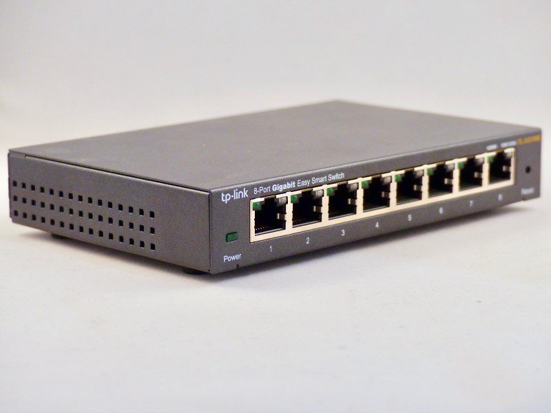
A cluster works by communication. A ‘master’ node is in charge of the cluster and the ‘workers’ are told what to do and to report back the results on demand. To achieve this we’re using wired Ethernet on a dedicated network. It’s not essential to do it this way, but for data-intensive applications it’s advisable for the cluster to have its own private link-up so it can exchange instructions without being hampered by wireless LAN or other network traffic. So, in addition to wireless LAN, we’re linking each node to an isolated Gigabit Ethernet switch.
Raspbian ripple
We’re going to access each node using wireless LAN so the Ethernet port is available for cluster work. For each ‘node’, burn Raspbian Buster Lite to a microSD card, boot it up, and make sure it’s up to date with sudo apt -y update && sudo apt -y upgrade. Then run sudo raspi-config and perform the following steps:
• Change the ‘pi’ user password.
• Under ‘Networking’, change the hostname to nodeX, replacing X with a unique number (node1, node2 etc.). Node1 will be our ‘master’.
• Enable WiFi if desired.
• Exit and reboot when prompted.
Get a backbone
The wired Ethernet link is known as the cluster’s ‘backbone’. You need to manually enable the backbone, as there is no DHCP server to help. We’re going to use the 10.0.0.0 subnet. If your regular network uses this, choose something different like 192.168.10.0. For each node, from the command line, edit the network configuration:
sudo nano /etc/dhcpcd.conf Go to the end of file and add the following:
interface eth0
static ip_address=10.0.0.1/24
For each node, replace the last digit of ’10.0.0.1’ with a new unique value: 10.0.0.2, 10.0.0.3, and so on. Reboot each node as you go. You should be able to ping each node – for example, from 10.0.0.1:
ping 10.0.0.2
Brand new key
For the cluster to work, each worker node needs to be able to talk to the master node without needing a password to log in. To do this, we use SSH keys. This can be a little laborious, but only needs to be done once. On each node, run the following:
ssh-keygen -t rsa
This creates a unique digital ‘identity’ (and key pairs) for the computer. You’ll be asked a few questions; just press RETURN for each one and do not create a passphrase when asked. Next, tell the master (node1, 10.0.0.1 in our setup) about the keys by running the following on every other node:
ssh-copy-id 10.0.0.1
Finally, do the same on the master node (node1, 10.0.0.1) and copy its key to every other node in the cluster.
Install MPI
The magic that makes our cluster work is MPI (Message Passing Interface). This protocol allows multiple computers to delegate tasks amongst themselves and respond with results. We’ll install MPI on each node of our cluster and, at the same time, install the Python bindings that allow us to take advantage of its magical powers.
On each node, run the following:
sudo apt install mpich python3-mpi4py Once complete, test MPI is working on each node
mpiexec -n 1 hostname
You should just get the name of the node echoed back at you. The -n means ‘how many nodes to run this on’. If you say one, it’s always the local machine.
Let’s get together
Time for our first cluster operation. From node1 (10.0.0.1), issue the following command:
mpiexec -n 4 –hosts 10.0.0.1,10.0.0.2,10.0.0.2,10.0.0.4 hostname
We’re asking the master supervisor process, mpiexec, to start four processes (-n 4), one on each host. If you’re not using four hosts, or are using different IP addresses, you’ll need to change this as needed. The command hostname just echoes the node’s name, so if all is well, you’ll get a list of the four members of the cluster. You’ve just done a bit of parallel computing!
Is a cluster of one still a cluster?
Now we’ve confirmed the cluster is operational, let’s put it to work. The prime.py program is a simple script that identifies prime numbers. Enter the code shown in the listing (or download it from magpi.cc/EWASJx) and save it on node1 (10.0.0.1). The code takes a single argument, the maximum number to reach before stopping, and will return how many prime numbers were identified during the run. Start by testing it on the master node:
mpiexec -n 1 python3 prime.py 1000
Translation: ‘Run a single instance on the local node that runs prime.py testing for prime numbers up to 1000.’
This should run pretty quickly, probably well under a second, and find 168 primes.
Multiplicity
In order for the cluster to work, each node needs to have an identical copy of the script we need to run, and in the same place. So, copy the same script to each node. Assuming the file is in your home directory, the quick way to do this is (from node1):
scp ~/prime.py 10.0.0.x:
Replace x with the number of the node required: scp (secure copy) will copy the script to each node. You can check this has worked by going to each node and running the same command we did on node1. Once you are finished, we are ready to start some real cluster computing.
Compute!
To start the supercomputer, run this command from the master (node1):
mpiexec -n 4 –host 10.0.0.1,10.0.0.2,10.0.0.3,10.0.0.4 python3 prime.py 100000
Each node gets a ‘rank’: a unique ID. The master is always 0. This is used in the script to allocate which range of numbers each node processes, so no node checks the same number for ‘primeness’. When complete, each node reports back to the master detailing the primes found. This is known as ‘gathering’. Once complete, the master pulls all the data together and reports the result. In more advanced applications, different data sets can be allocated to the nodes by the master (‘scattering’).
Final scores
You may have noticed we asked for all the primes up to 1000 in the previous example. This isn’t a great test as it is so quick to complete. 100,000 takes a little longer. In our tests, we saw that a single node took 238.35 seconds, but a four-node cluster managed it in 49.58 seconds – nearly five times faster!
Cluster computing isn’t just about crunching numbers. Fault-tolerance and load-balancing are other concepts well worth investigating. Some cluster types act as single web servers and keep working, even if you unplug all the Raspberry Pi computers in the cluster bar one.
Top tip: Load balancing
Clusters are also useful for acting as a single web server and sharing traffic, such as Mythic Beast’s Raspberry Pi web servers.
Top tip: Fault tolerance
Certain cluster types, such as Docker Swarm or Kubernetes, allow individual nodes to fail without disrupting service.
-
Perpetual Chimes project showcase
Reading Time: 3 minutesThe Perpetual Chimes project is very clever – a set of augmented wind chimes which, since they are indoors, require the user to interact with them in order to create an escapist soundscape played through headphones.
Frazer Merrick, a sound artist and educator, Frazer enjoys circuit bending, field recording, and physical computing. He came up with the idea for the chimes while experimenting with ways of creating interactive musical instruments, and exploring how sounds can transform a space. “At the time I was really interested in escapism,” he recalls, “so I knew I wanted to make a headphone-based interactive installation that captivated the player/listener – something that didn’t make much acoustic sound, but instead something just for the player.”
Frazer initiated the idea back in 2016, creating a prototype where the chimes were suspended from a brake disc hanging from a mic stand. Keen to improve on this first version, Frazer and a collaborator from @LimboEducation began work again in 2018 to revive and improve the project: “We set to work making it far more robust and, importantly, standalone.”
The sound of music
So, how do the chimes work? Frazer explains, “When you hit one of the chimes, it strikes a disc in the middle. Both these elements are connected to a Makey Makey (the central disc being ‘earth’), which then triggers a key press on [the project’s] Raspberry Pi. I programmed a patch in Scratch to play audio files when it receives these key presses, which you then hear over the headphones. There is no acoustic sound other than the dull clunk of stainless steel and copper pipes hitting one another. However, in the headphones is an atmospheric soundscape of calming field recordings and synthesizer drones.”
Frazer made the recordings using the Alchemy synthesizer in Logic Pro. “I used the amplitude of a waterfall recording (which I made in the Isle of Mull) to affect different parameters of the synthesizer,” he says. “In Scratch, there’s a variable counting every time the chimes ‘strike’ and when this is a modulus of 25, one of three large pulsating bass notes plays too, adding an element of surprise to the installation and encouraging you to keep playing and discovering more combinations of notes. Alongside this is a subtle field recording of the coastline from the same peaceful trip to the Isle of Mull, completing the escapist soundscape.”
Heavenly harmonies
Sounds idyllic, and Frazer has clearly enjoyed seeing people explore the possibilities of the chimes: “It’s so rewarding to see people playing and smiling with the chimes, creating their own soundscapes by activating them (some harder than others). My favourite comment was someone who called the work ‘curious’, as this summed up my work so much better than I ever could.”
Frazer admits that it was a challenge to fit all of the components inside the head unit of the chimes, but “after cutting down a few cables and shuffling things around, I managed to fit it all in. Thankfully the support system is designed so I can easily adjust the hanging height from the beam above, which is very useful when installing in different venues.”
It was also his first project with a Raspberry Pi, which he used “because I wanted the chimes to be unmanned and to be installed for long periods of time, all without having to worry about securing a laptop somewhere behind the scenes.”
Quick facts
-
Frazer 3D-printed the case for the electronics
-
Frazer exhibited the chimes at Colchester School of Art
-
A lot of holes needed to be drilled in the project!
-
The Scratch code can be found at magpi.cc/gPpuw4
-
Frazer plans to switch from Scratch to Pure Data for better audio quality
-
-
Flirc Raspberry Pi 4 case review
Reading Time: 3 minutesHere’s where things get clever: inside the case is a protruding heat sink that reaches down to Raspberry Pi 4’s CPU. This turns the whole of the aluminium case into a giant heat sink, cooling down your Raspberry Pi 4.
Inside the pack is a square thermal pad (similar in substance to Blu Tack). You use this to squidge the Raspberry Pi to the heat sink. Putting together the case is ludicrously simple: you simply drop a Raspberry Pi in the bottom half, attach the thermal paste, squidge down the lid, and use four screws to hold everything together.
Flirc claims that this is “the most beautifully crafted Raspberry Pi 4 case” and it’s not a wholly unwarranted claim. It certainly has a sense of style. Everything is neatly constructed from high-quality materials and there’s considerable charm to the heat sink. The microSD card slot is easily accessible, and a small cut-out on the enclosure enables the LEDs to shine through.
On the box
One downside to the sealed approach is that the GPIO pins are hidden away inside the case. Unlike the official case, the lid cannot be quickly removed to provide access to the pins. To Flirc’s credit, it has addressed this issue via a small gap on the underneath of the Flirc Raspberry Pi 4 case, which could be used with a breakout I/O cable. But it’s an ungainly addition to such a lovely looking case.
If you plan to use Raspberry Pi as a desktop computer, then this might be a valid trade-off. However, for many of us, GPIO pins are the very essence of Raspberry Pi.
Under pressure
We stress-tested a Raspberry Pi 4 board on its own vs a Raspberry Pi 4 inside the Flirc case to see what temperatures it reported.
WARNING!: Stress testing should only be done for short periods. Watch your Raspberry Pi and restart afterwards.
We used stress (apt install stress) and the following script from Core Electronics to test our Raspberry Pi 4 while measuring temperature:
while true; do vcgencmd measure_clock arm; vcgencmd measure_temp; sleep 10; done& stress -c 4 -t 300sThis puts all four cores of Raspberry Pi 4 under stress. For each test, we left the Raspberry Pi to run for five minutes. Warning! Don’t do this at home without doing your research first. Unsurprisingly, the Raspberry Pi with no heat sink attached quickly went up to 79 °C and hovered at that level for the rest of the test, nudging up against (but not pushing over) the level where Raspbian starts to throttle the CPU.
Next, we put a Raspberry Pi into the Flirc Raspberry Pi 4 case and ran the same test. This time it idled at a mere 28 °C and our five-minute stress test took it up to a mere 46 °C. Because this is comfortably below the threshold, it opens up a world of overclocking (something that has been reintroduced on Raspberry Pi 4).
We took the CPU clock speed up to 1.75GHz. The overclocked Raspberry Pi (inside the Flirc case) idled at 41 °C, and running our five-minute stress test took it up to 67 °C. Again, comfortably within a threshold. We also played around with CPU clock speeds up to 2.0GHz, which idled at 48 °C and maxed out at 69 °C.
We’re going to experiment some more with overclocking, which makes this a fun case. Expect a tutorial shortly.
Verdict
8/10
We love the style of the Flirc case, and its heat sink opens up a world of overclocking. If only the GPIO pins remained accessible. If that’s not a deal-breaker for you, though, then this is a great case to get.