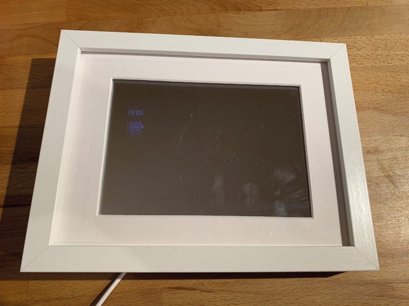
Schlagwort: raspberrypi

  • CNC Etch-A-Sketch

    CNC Etch-A-Sketch

    Reading Time: 2 minutes

    Shaking things up

    “I had no idea the Raspberry Pi was so powerful,” he says. “But when I discovered it was capable of driving stepper motors using programs such as bCNC, I knew I’d found my solution for a portable CNC Etch-A-Sketch.” Indeed, his use of our favourite computer meant he could produce a wireless unit that was so light and sturdy, it could also be picked up and shaken to clear the display without causing any damage.

    “Other projects have connected stepper motors to an Etch-A-Sketch, but the makers have quickly found they have to take the whole thing apart just to reset the screen,” Quint tells us. “That’s something I’ve never had to worry about because I spent a lot of time designing and producing a strong frame. It meant more work up front, but was well worth it in the long run.”

    Even so, the challenge didn’t stop there. As with all CNC machines (those which use software connected to a tool to automate control such as 3D printers), simple x and y co-ordinate commands are issued. “You’re basically telling the machine ‘go here, go there, now here, now there’ using commands known as G-code,” Quint explains. Coding is, therefore, crucial.

    A standard Etch-A-Sketch toy is able to display whatever image is outputted via the bCNC program installed on Raspberry Pi

    Turning things around

    For this, Quint used variations of the G-code command G1, noting the required x/y position and the required speed. “As an example, G1 X40 Y60 F400 means go 40 mm to the right and 60 mm up at a speed of 400 mm per minute,” he says. “Using  small enough line segments, you can even draw a circle!”

    The first real problem he encountered was the looseness in the Etch-A-Sketch mechanism when changing directions. “You have to turn the wheels further than you think – if you mark an Etch-A-Sketch dial and bring it to the same spot from both directions, you’ll get about a 1.5 mm mismatch which can make your sketches look really poor. Most CNC software has ‘backlash compensation’ to account for this, but bCNC does not. Fortunately, I stumbled on a free program called NoLash that adds backlash compensation to the G-code program itself. You just tell it how much to compensate for and it does the job for you.”

    Now, by firing up bCNC, Quint can create an image and have it replicated on the Etch-A-Sketch screen with the knobs being automatically manipulated. It has also allowed for some very elaborate designs, which have impressed all who have seen them being created. “Once I got it figured out, everything worked really well,” he says. “The experience has been magical.”

    For the creation of stop-motion videos, the camera sits behind black fabric to prevent reflections, and each image is drawn 1 to 2 mm apart for smooth footage

  • Adafruit 1.3″ Color TFT Bonnet

    Adafruit 1.3″ Color TFT Bonnet

    Reading Time: 3 minutes

    What’s it for?

    So, if a device so reminiscent of a classic console isn’t for gaming, what is it for? The Bonnet shares a heritage with Adafruit’s Mini PiTFT. That device features the same square 33 mm display, but has just the two buttons. This Adafruit 1.3″ Color TFT Bonnet comes with the five-way joystick to enable more complex interface interactions (the fifth direction is a push inwards, incidentally).

    Like the Mini PiTFT, the Adafruit 1.3″ Color TFT Bonnet also features a Qwiic/STEMMA QT connector for I2C sensors. And this is where things become clearer. You can plug and play Adafruit’s range of STEMMA QT devices, which includes all manner of sensors: magnetometers, temperature, pressure, proximity, and so on.

    It is in this area where the Adafruit 1.3″ Color TFT Bonnet comes alive. What we have here isn’t the heart of a portable games console, but an interface for a range of sensor projects. In that spirit, it is something of a shame that the Bonnet covers the entire 40-pin GPIO header, unlike the Mini PiTFT which leaves 16 pins free. But the STEMMA QT connector provides your I/O needs.

    Kernel or Python

    Setup of the Adafruit 1.3″ Color TFT Bonnet was straightforward, although the linked instructions are for the two-button Adafruit Mini PiTFT.

    There are two approaches: use a script to install a kernel module, or use Python and the Pillow library to draw images on the display.

    Crucially, you can’t use both techniques at once. This is a shame as the kernel module is faster and, arguably, more fun. But once it’s installed, you can’t move on to using Python.

    The kernel method is also more accessible method for beginners. Run a script and you can mirror the Raspbian with Desktop interface on the tiny 1.3-inch display.

    It’s fun but wholly impractical. Not quite ready to give up our dream of a teeny console, we attempted to install PICO-8 in this mode and while it did run, the experience was (as Limor claimed) too small.

    The kernel installation script also enables you to run Raspberry Pi in a console mode. Text mode is better, if you have very good eyesight, but it’s still lacking an effective use case. According to Adafruit, the Bonnet runs at 15 fps in kernel mode, so it is better suited to simple animations and video (neither of which is fun to watch on such a small display).

    This leaves the second, more practical, option. Which is to follow the Python setup guide. This approach is (according to Adafruit) more stable and allows you to write Python code to control the display.

    You need to install the Adafruit_Blinka library that provides CircuitPython support in Python. Once up and running, you can follow the tutorials to create your own display interfaces, and there are examples on the site. From here, you will be able to create interfaces that display information, and interact with your range of I2C sensors.

    The screen is sharp, and lovely to look at, but it’s so small that it strikes us as a bit fiddly for anything complicated.

    Verdict

    7/10

    We found this a bit of a head-scratcher, and we’d be interested to hear from makers who find it fits their use case. Unless you know exactly what you’re going to make with it, we suggest going for the simpler two-button Adafruit Mini PiTFT.

  • Customise your Raspberry Pi magic mirror with modules

    Customise your Raspberry Pi magic mirror with modules

    Reading Time: 6 minutes

    Building a magic mirror is one of the easiest, and most rewarding Raspberry Pi projects. Follow our Build a magic mirror tutorial to get your own mirror up-and-running.

    The rear view shows the mounted monitor and Raspberry Pi computer. Removing the monitor’s bezel gets the screen as close as possible to the surface

    Orientate your magic mirror

    Can a mirror be upside-down? A magic mirror can! Most mirrors tend to be portrait, whereas screens are normally landscape. Normally we could make some changes to /boot/config.txt to easily rotate the screen, but with Raspberry Pi 4’s fancy new graphics support, this is no longer possible. To rotate your display 90º so it fits your mirror, open a Terminal and enter the following:

    /etc/xdg/lxsession/LXDE-pi/autostart

    Now add this line to the end of the file:

    @xrandr --output HDMI-1 --rotate right

    Save the file (CTRL+X) and reboot. Your display should now be portrait.

    Safety first

    Sadly, MagicMirror2 doesn’t (yet) come with an easy configuration utility. For now, you will need to do some text editing of config.js. Don’t worry: as long as you make copies of your files, it’s going to be hard to break anything. If MagicMirror2 refuses to start, just copy the file back. Here’s how it works from a Terminal:

    cd ~/MagicMirror/config
    cp config.js config.js.backup

    If anything goes wrong, just copy the config backup back and try again:

    cp config.js.backup config.js

    Each time you edit config.js, you’ll need to restart MagicMirror2 for changes to take effect. To do this at any time:

    pm2 restart MagicMirror 

    Meet the config file

    Your config file controls some of the fundamental features of your mirror, as well as the various modules. It is formatted in a JavaScript file. This is a very well-structured language but unforgiving. A misplaced ‘{’ or ‘[’ and nothing will work (hence the previous step). The config.js.example file is a great way to explore without changing anything. You’ll see how to change the ‘zoom’ (text size), units (metric or imperial), and whether you want a 24-hour clock or not. Most importantly, the ‘modules’ section controls which modules (code that gives certain functionality) are loaded and where they’re placed.

    Here’s a section of the config file. It’s JavaScript code so may look a little different if you’re used to Python

    Tip! Learn JSON

    If you’re serious about configuring MagicMirror2, knowing the JSON data format is essential. Have a look at json.org.

    The default MagicMirror2 modules

    MagicMirror2 comes with a selection of modules pre-installed. Start by tailoring them to your specific needs. Find the ‘modules’ section in config.js. Within the two square brackets are sections contained within curly brackets: { }. Each one is a single module. Each module has different requirements but each one requires a ‘module’ line like this:

    module: "name-of-module",

    Most also require a ‘position’, which can be ‘top_bar’, ‘top_left’, ‘lower_third’, and many others. This controls where the module is displayed on the mirror. If a title is required, then ‘title’ allows you to change the text of the header. Finally ‘config’ will contain information that is specific to that module.

    There are many, many modules available for all kinds of uses. This one shows you a daily Pokémon!

    Whatever the weather

    Let’s use the weather module as an example. Under ‘modules’, find ‘weatherforecast’. You have the option to change the title (maybe ‘Will it rain?’) and the position of the module on the screen. In ‘config’ you have three pieces of information to complete. To get your own weather forecast, go to openweathermap.org and register for a free account. You can then create an API key (a secure way of your mirror communicating with the service), which you need to specify here in ‘appid’. Change the name of your location as you wish and finally change the location ID to the correct one listed in this file: magpi.cc/citylist. Restart MagicMirror2 and see your local weather!

    Breaking (glass) news

    The default news feed on the mirror comes from The New York Times, which may not be your cup of tea. The ‘newsfeed’ module works with any RSS feed, of which there are millions to choose from (and you can have multiple newsfeeds if you wish). Let’s change the newsfeed to the BBC. Find the module ‘newsfeed’ and you’ll see under ‘config’ the ‘feeds’. This is surrounded with square brackets [ ], which means we can have multiple entries. Change ‘New York Times’ to ‘BBC News’ and the ‘url’ to ‘http://feeds.bbci.co.uk/news/rss.xml’. Restart MagicMirror2 and now you’re getting the headlines from the UK.

    Vampire mode (no reflection)

    By now you may be finding it a little frustrating if you’ve already put up your mirror. With a bit of reconfiguration, you can access the mirror display using a web browser and work on it from your desktop. Edit config.js and have a look at the first few lines under ‘config’. These control access to the display. It’s locked down by default (which is good), but we can allow other computers access. Change these following lines as shown:

    address: "",
    ipWhitelist: []

    This allows any IP address on your network to access the server. You’ll need to restart MagicMirror2 for changes to take effect. Now you should be able to see your display at http://<your mirror’s IP address>:8080.

    It may be easier to configure your screen before mounting it in the mirror

    Client and server mode

    The reason we can so easily see the display in a web browser is that MagicMirror2 is split in to two parts: the client, the software that displays the screen; and the server, which generates the content. This clever split allows you to generate the content from a separate computer on the network, which is handy if you want to do something really intensive. It also allows you to have multiple mirrors that all show the same display, which makes rolling out changes really easy.

    To start an installation of MagicMirror2 without a display (server):

    node serveronly

    To create a client that gets its content from the server:

    node clientonly --address <ip of server> --port 8080

    Editing modules

    Let’s have a look at modifying existing modules. You’ll have seen in the centre of the screen, there are ‘compliments’ rotating every few seconds. You can change these in config.js, but let’s look in the actual code so we can get a feel of how things are arranged. In Terminal, navigate to where the default modules are installed:

    cd ~/MagicMirror/modules/default

    If you do an ls to get a directory listing, you’ll be able to tell what’s available. We’re interested in the ‘compliments’ module:

    cd compliments

    Now edit the file:

    nano compliments.js

    Look at the various text strings and change them to whatever you like. Save the file and restart MagicMirror2 to see your new messages. A sample compliments.js file can be seen here.

    More MagicMirror2 modules

    Great news: you are not restricted to the default modules. There are hundreds of community-built modules that are free to download and install. They cover all kinds of useful information, including stock prices, local transportation, prayer guides, and even how your local Minecraft server is holding up. Luckily, a directory of MagicMirror2 modules is maintained on the main site’s wiki.

    Most modules will require some configuration, so make sure you look at the README file and follow the instructions carefully. There’s no limit to how many modules you can have, bar the positions available on the screen.

    Installing modules

    Sadly, we don’t have a nice package manager for MagicMirror2, so installing modules tends to involve using Git to fetch the code. For an example, we’re going to install ‘Daily Pokemon’. From the Terminal, we’ll go to the modules directory, then get the code from GitHub.

    cd ~/MagicMirror/modules
    git clone https://github.com/NolanKingdon/MMM-DailyPokemon
    cd MMM-DailyPokemon
    npm install

    The final command gets all the libraries that the module needs to run. Once completed, edit the config file:

    nano ~/MagicMirror/config.js

    Create a new line after modules: [ and add the code from the Figure 1 listing (or use the download link for the full, edited config.js file). Make sure you end with a comma. Restart MagicMirror2 and admire your daily Pokémon.

    More MagicMirror2 modules

    As we’ve already said, there’s a dizzying array of modules to choose from, and you can even write your own. If you’re in the mood for customising, here are a few of our favourites. You can find all of them, along with installation instructions at magpi.cc/mirrormodules.

    magpi.cc/mmmstocks

    Every information screen needs a stock ticker, right?

    magpi.cc/mmmwiki

    Up your knowledge as you get ready to leave the house with these random snippets from Wikipedia.

    magpi.cc/mmmukrail

    Is your train going to be on time? If you’re in the UK, this module will let you know. Many other countries have equivalent modules too.

    Click here to download the full code.

    modules: [ { module: "MMM-DailyPokemon", position: "top_center", config: { updateInterval: 600000, minPoke: 4, maxPoke: 151, grayscale: true, showType: true, language: "en", genera: true, gbaMode: true, nameSize: 26 } },
  • Raspberry Pi problems solved in The MagPi 92

    Raspberry Pi problems solved in The MagPi 92

    Reading Time: 2 minutes

    Click here to buy The MagPi magazine issue #92

    Raspberry Pi Problems Solved

    Raspberry Pi problems solved

    Learn to diagnose and fix issues with Raspberry Pi. Get rid of glitches and odd behaviour, sort out boot problems, reconnect networking problems, and discover advanced troubleshooting tips.

    Magic Mirror facial recognition

    Facial recognition with a magic mirror

    PJ continues his incredible journey into the world of magic mirror technology. This month, he adds facial recognition to the project with OpenCV. Gaze into the glass and it gazes back, adjusting its behaviour to your lovely visage. Get personalised calendar events, notifications, and alerts.

    Track local weather & pollution

    Track local weather & pollution with Raspberry Pi

    Build a weather station in your own garden. This project is a fantastic way to explore science and meteorology from the comfort of your own garden.

    Inside our feature you’ll find a range of weather projects and builds that can track just about anything. Then we use the new Enviro board to track air quality and particulate matter.

    Instaclock

    The best project showcases: like Instaclock, Chamber Sourdough Incubator, and Solar-powered Camera

    You’ll find the best Raspberry Pi projects in The MagPi, and this month we have an incredible selection for you to look at. 

    Instaclock uses twin screens to display images of four numbers taken from Instagram to show the time. You’ll also find Chamber: Sourdough Incubator – a project using Raspberry Pi to keep a sourdough starter at the right temperature – and a solar-powered camera that keeps itself running in remote locations.

  • Win one of ten Argon ONE cases!

    Win one of ten Argon ONE cases!

    Reading Time: < 1 minute

    Subscribe

  • Raspberry Pine

    Raspberry Pine

    Reading Time: 2 minutes

    Wood-n’t it be nice

    The screen is mounted in a custom pine frame and stand. The frame is built using strips of small pine architrave backed by pine strips, offset to give a suitable rebate for the panel to fit and hiding the border. The side supports are modified pine staircase spindles. A Perspex sheet is used to mount the electronics and, when powered, the panel backlight creates a warm glow. Finally, short lengths of foam draft excluder secure the panel sandwiched in the frame.

    The LCD panel has a driver board with HDMI, DVI, and VGA inputs. This is connected to the project’s Raspberry Pi 3B+ by a short HDMI lead, with left- and right-handed adapters. This caused a headache for Neil: “I think the biggest challenge was sourcing the LCD panel driver board from a UK supplier on eBay. Unfortunately, the only documentation you get is from the tiny screen printing on the board itself.”

    The rest of the electronics supply and manage power. The main supply is the original PSU brick from the donor laptop, providing 19.5 V at 4.5 A. Two DFRobot PSU boards are used to drop the 19.5 V to 5 V for Raspberry Pi, and 12 V for the LCD driver board, enough to power the backlight.

    The rear is an exposed collection of controller board and, of course, the project’s Raspberry Pi 3B+

    There is also the option of battery power, from three Li-ion cells recovered from another laptop. A battery management system (BMS) board sits on top of it and ensures the cell charge states are balanced. Finally, a charger board provides the correct constant current and voltage charge profile.

    A tree-mendous result

    The result is a very different take on the classic desktop project: a computer that would look just as at home on the bedroom dressing table as it would in the study. Neil was certainly pleased with the results, as well as an unplanned effect: “The choice of raspberry-coloured Perspex as the support for the electronics produced a pleasant surprise. When powered on, the LCD backlight gives a raspberry glow.”

    Regarding planned further refinements, he tells us: “When the Raspberry Pi 4B+ gets the update to boot from USB, there may be a rebuild to refine the layout so the SSD doesn’t stick out the side. Currently, the donor laptop keyboard is being developed with an Arduino Due and more pine. There are thoughts of matching mouse and speakers.”

  • Learn SQL and database design with Raspberry Pi

    Learn SQL and database design with Raspberry Pi

    Reading Time: 3 minutes

    SQLite

    SQLite’s site is basic, but sqlitetutorial.net provides free interactive training. As well as covering SQL for SQLite (all platforms have slightly different implementations of SQL), there is a Python-specific course. Here, you can learn how to use PySQLite, the Python bindings for SQLite. Not only is the SQL language covered, but how to create databases and tables in Python. This makes for a comprehensive combination of courses.

    MariaDB

    MariaDB/MySQL

    The next logical step from SQLite is to move to a full relational database server. A popular choice is MariaDB, an open-source project based on, and fully compatible with, MySQL. MySQL is probably one of the most popular database servers of all time. Both variants are free, but MariaDB boasts a new ‘engine’ that provides significant speed increases. Installing the server is straightforward and it runs surprisingly fast, even on older Raspberry Pi hardware. Once installed, you’ve more to think about than with SQLite, such as users and permissions. Thankfully, MariaDB offers online courses for free – a nicer way to learn than ploughing through dry documentation. This is a powerful platform: it can take tables containing millions of rows in its stride. It’s possible to use MariaDB/MySQL for anything from your own logging project, to enterprise-grade applications.

    MongoDB

    MongoDB

    Certain applications or projects require a different type of database. If you’re looking at storing lots and lots of simple data and don’t require the kind of data extraction that relational databases offer, then a NoSQL (or document) database may be for you. This family of databases specialise in high-volume, fast data storage and retrieval. They are especially popular when the job is to ‘just get the data and store it as quickly as possible’. Rather than using the traditional model of tables, columns, and rows, document databases use schemas and key-pairs to store data. MongoDB is a popular open-source server. It’s very easy to install, and you can undertake a full course.

    The Definitive Guide to SQLite

    Grant Allen and Michael Owen’s book on SQLite is a comprehensive look at this ‘micro’ database. Despite its small footprint, the authors reveal an incredibly powerful engine and some surprising applications including embedded systems.

    MySQL for Python

    Python being the preferred choice of language of the Raspberry Pi Foundation, this book is a perfect introduction to using Python’s MySQL wrappers. The MySQL for Python book is formatted as a series of tutorials that increase with complexity.

    MongoDB and Python

    Like the aforementioned MySQL for Python book, this one gets right to the point. It uses the ‘recipe’ format, so you can find a close match for the problem you want to solve, and see how using MongoDB can help.

    Udemy SQL Video courses

    Intro To SQLite Databases for Python Programming

    A great ‘back to basics’ video course which takes you through all the steps of installing and using SQLite. Intro to SQLite Databases for Python Programming is 90 minutes of video in bite-size pieces.

    Using MySQL Databases With Python

    Just like for SQLite, Udemy offers a full nothing-to-something course on using MySQL Databases with Python. The two hours of video usefully cover installation of the server.

    MongoDB and Python: Quick start

    Crucially, this MongoDB and Python: Quick Start two-hour video course covers when to choose a NoSQL (or document) database and the key differences between this and traditional SQL engines.

  • NexDock 2 review

    NexDock 2 review

    Reading Time: 2 minutes

    And what a lovely screen it is: the 13.3-inch IPS 1920×1080 display is a delight to look at, even if the chunky borders are a bit retro. The edge-to-edge full-sized backlit keyboard is equally impressive, with responsive chiclet-style keys that are suitably clicky. Typing is a breeze.

    The whole thing is set off in a grey and black style that’s far more professional than its price tag warrants.

    And we’re trying hard to ignore the unfortunate bulge in the plastic hinge above our F2 key. Perhaps we got an early run that slid through the checks.

    Battery life

    Inside NexDock 2 sits a 51 Wh battery that provides power to the screen and keyboard and Raspberry Pi. We ran our fully charged unit with Raspberry Pi 4 playing YouTube videos from 10:10 to 15:22, just over five hours of solid playback.

    A supplied 60 W USB-C adapter is used for charging.

    Plugging in

    In the box is an HDMI cable with a micro-HDMI to HDMI adapter for Raspberry Pi 4. Meanwhile, a USB-C cable splits out to USB-A and micro-USB (for power and keyboard/mouse connection). That’s a lot of cabling compared to a regular laptop. The nest of cables is an issue.

    We managed to bend the connection on the HDMI-to-micro-HDMI adapter, and replaced it with the white extension cable (pictured above). Be sure to disconnect everything when you pack up.

    Achilles’ trackpad

    The weakest link is the trackpad. There’s no thumb rejection – so as you type, the cursor jumps around the screen. And if you use a thumb to click, the cursor jumps from the clicked point.

    Our solution is to attach a USB and disable the trackpad with xinput:

    xinput --set-prop "SINO WEALTH USB KEYBOARD Mouse" "Device Enabled" 0

    To re-enable the trackpad:

    xinput --set-prop "SINO WEALTH USB KEYBOARD Mouse" "Device Enabled" 1

    The lack of hardware and software integration soon becomes apparent. Closing the screen shuts off the power to the display, but not immediately to Raspberry Pi, which carries on running for a short time until the power is yanked. We took to using shutdown -h now when done and removing all the cables.

    Digital nomad

    Using Raspberry Pi with NexDock 2 as your go‑to laptop is stretching credibility. The finicky trackpad, nest of wires and dongles, and lack of creature comforts will drive you round the bend.

    However, NexDock 2 is ideal for users who need to power up a Raspberry Pi at an event. We imagine Pi Jam-goers and folks at Pi Wars will find NexDock 2 a very handy device to have around.

    Verdict

    8/10

    An incredibly useful, yet far from perfect, solution to using Raspberry Pi on the move. Despite its flaws, it is, by far, the best solution we have found to this particularly thorny problem.

  • AdventurePi: portable Raspberry Pi arcade machine

    AdventurePi: portable Raspberry Pi arcade machine

    Reading Time: 3 minutes

    When pondering his next project with a Raspberry Pi, he decided to create AdventurePi, a portable gaming device that would be as robust as an arcade machine.

    “A lot of people my age move around a lot or live in apartments and no one really wants to lug around a free-standing cabinet, so I looked to create a device that would feature full arcade controls.”

    In fact, Zach ended up creating two different versions of his project. As well as an Arcade Edition that features a removable panel containing arcade buttons and a removable joystick, he produced a Console Edition that uses a foam block insert with cutouts for controllers and accessories.

    “My primary goal was to make the project as accessible as possible and introduce more people to Raspberry Pi, hobby electronics, and retro gaming,” he says, opting early on to use the RetroPie OS which allows games originally made for older systems to be enjoyed with minimal fuss via emulation.

    If you like this then take a look at our Retro gaming with Raspberry Pi book. It’s packed with retro gaming projects and tutorials.

    AdventurePi: quick facts

    • The project cost about $250, overall

    • There are two versions: Arcade and Console Editions

    • It displays to a 13.3-inch screen

    • It uses RetroPie for emulation

    • Strong nylon fasteners secure the components

    The Console Edition is essentially a Raspberry Pi with RetroPie installed connected to a display in a case with foam inserts for controllers and accessories

    Build a Portable Raspberry Pi arcade machine

    Since RetroPie does not yet work on a Raspberry Pi 4, Zach had to use the 3B+ model instead. Planning proved to be the trickiest part of the setup, but he knew he needed a display that could run on either 12 V or 5 V, and a single power supply that would output enough amperage to run the screen and Raspberry Pi simultaneously for hours.

    “From there, it was a matter of finding a sturdy case that had a removable panel for the Arcade Edition and a foam insert for the Console Edition,” he says. A Nanuk 910 waterproof hard case worked well, requiring only a little bit of shaving to the inside with a box cutter so that the screen would fit nicely in the lid, while allowing room for the wires. “I found some slim 90 degree cables normally used on drones, because there wasn’t the space for normal micro USB and HDMI cables,” he says.

    To avoid the controller smashing into the screen when the case is closed, the joystick unscrews for easy storing

    Add a USB controller

    For the Arcade Edition, Zach had to essentially build a USB controller. “I made use of illuminated buttons and a joystick connected to a small PCB that turned the setup into a USB device,” he explains. He took inspiration from Pimoroni’s Picade cabinet. “The controls use the same layout because I figured they’d worked things out already.”

    Even so, Zach encountered a problem that almost killed the project before it started: how to add a joystick within a closable case. “I messed around with a few hinging mechanisms and then found a company that makes a removable joystick,” he says of the fortunate solution. As for the Console Edition, that has been a case of cutting the foam to house controllers, chargers, wires, and other gaming peripherals that can connect to the Raspberry Pi, but the fun isn’t stopping there. Zach believes AdventurePi will eventually be developed as a much smaller version using a custom power supply. “I’d also like to add a power button that automatically shuts [Raspberry] Pi down when the case is closed,” he says.

  • Get started with electronics and Raspberry Pi

    Get started with electronics and Raspberry Pi

    Reading Time: 8 minutes

    Raspberry Pi is the gateway to electronics and computing

    Raspberry Pi has made a huge impact, not only on computer science education but also in the realm of makers and inventors. As well as being a really good-value computer, it gives the owner endless possibilities of connecting other electronics to it to produce useful gadgets and impressive demonstrations.

    Raspberry Pi is your gateway to the new frontier of creative technology. If you can master the basics of how to connect electronics to a Raspberry Pi, you can use the same techniques to start inventing your own gadgets and electronic tools. If these are your first steps into electronics, you have a very exciting journey ahead.

    See also:

    Expand and experiment

    In the early days of home computers, most models had expansion ports of one sort or another and, very often, upgrading them involved opening up the case and soldering new circuits, or at least plugging in chips into empty slots. These days, you are lucky if your home computer has USB connectors for accessories, and plugging in home-made contraptions is definitely not recommended.

    Raspberry Pi is different because its design encourages the owner to plug in extra devices and even experiment with your own prototype circuits. Raspberry Pi has standard USB and Ethernet ports, a camera connector, WiFi, and HDMI video output. But the crowning glory of connectivity is its GPIO (general-purpose input/output) 40-pin header, which provides the tinkerer with access to the inner workings of Raspberry Pi. You can even write code to control electronics that are plugged in to the GPIO pins.

    Getting started with GPIO electronics: what you’ll need

    If you are lucky enough to have a local electronics or hobby store, you will no doubt be able to find all the electronic components we will talk about for a few pounds, dollars, or euros. Failing that, there are many fully stocked online outlets that can provide them. All you will need to start with is a breadboard, some jumper leads, a resistor (200 Ω to 470 Ω), and an LED.

    Raspberry Pi GPIO pins

    You can use Raspberry Pi’s GPIO pins to pass electrical voltage to and from other components. Some of the pins have specific uses, such as power or ground connections, and others can be configured with software programs to send signals between Raspberry Pi and the rest of the circuit. Above is a breakdown of all the pins. Look carefully at physical pins 1 and 6: these will be the pins we use in our LED circuit later. Note that the pin numbers aren’t the same as the GPIO numbers; for example, GPIO 2 is actually physical pin 3.

    GPIO Pins on Raspberry Pi

    Prototype circuits with breadboards

    Breadboards come in several different sizes and are made of plastic with a matrix of holes. In each hole is a connector which joins it to other holes on the same row.

    Breadboards come in several sizes to enable prototyping of a wide variety of projects

    The larger breadboards have two long rows of holes at the top and bottom. Sometimes called ‘rails’, these are generally used for power and ground connections. They are connected together as indicated on the diagram above.

    The inner part of the breadboard has two sections of holes. Each section has rows of five holes which are connected as indicated on the diagram. The two halves of the breadboard are a mirror image of each other.

    The break along the centre of the breadboard, often known as the ‘gutter’, enables mounting of integrated circuits (chips) with the legs of the chip going either side of the break.

    Click here for a more detailed article on using a breadboard.

    A breadboard is used to connect electronics. All five holes in a row are connected; all the long blue and red lines on the end are all connected (and are used to for power)

    Basic prototyping components

    Here are the common prototyping components you will find:

    Jumper lead

    These connect your components to the Raspberry Pi. They can either have male or female end connectors (you need female for the GPIO pins) and it’s a good idea to have a mix of both.

    LED

    Light-emitting diodes come in various colours. They glow when electricity flows through them. Because they are a diode, the current will only flow in one direction, so make sure that it is connected the right way round: the longer leg is the positive one and should be connected to the power (or GPIO output) pin. Always use a resistor in series with LEDs, otherwise they are likely to draw more current than they can handle and burn out.

    LED

    Resistor

    Resistors are available in various formats, but this is the most common format for prototyping. The coloured rings around the resistor indicate how much resistance it provides. For more details about how to read resistor values, see The MagPi magazine issue 64.

    Use resistors to control the amount of electricity flow around your circuits

    Switch

    Switches make and break circuits. When connected in series in a circuit, a switch will allow or stop the flow of electricity. You can get switches that stay in the position in which they are set, or ones that you need to keep your finger on to keep the circuit connected.

    Speaker

    Speakers can be huge and very loud or they can be very small – small enough to fit on a breadboard. These small speakers are called piezoelectric and are great for making robotic noises, but not much good for hi-fi music applications.

    Speaker

    Capacitor

    Capacitors store and release electrical charge. They can be used to even out the electrical current or provide a greater flow for a short time. Be careful when using capacitors, as they can still hold charge after the circuit has been disconnected.

    Transistor

    Transistors are used in many types of circuits. They can be used either as an amplifier, which means that a small current goes in but a bigger current comes out, or as an electrical switch to change the amount of electricity flowing through circuit. A transistor has three legs or connectors: the emitter, the collector, and the base.

    Servo

    Servos are used a lot in robotics for making things move. They can be connected directly to Raspberry Pi via the GPIO pins, but there are also extra plug-in boards (or HATs) that make it easier to connect many servos and control them more easily. Normally we use digital servos which use PWM (pulse-width modulation) signals to turn the armature on the servo from one position to another.

    Servo

    Battery

    Batteries can be all kinds of shapes and sizes, but for simple electronics projects you will normally be using 1.5 V AA or AAA type cylindrical batteries or 9 V square ones. Make sure you always have some spares or perhaps you may want to use rechargeable ones. Rechargeable batteries cost more, but can be used over and over. Make sure you connect batteries correctly and never directly connect the two contacts together, as even small voltage batteries can get very hot or even explode if ‘short-circuited’.

    Potentiometer

    Potentiometers are variable resistors and usually have a twisting knob or a slider to change the resistance. They have three connectors and can be used as game controllers or volume controls. Be careful if you are using a potentiometer instead of a resistor in your LED circuit: if you turn the resistance right down to zero, you may burn out your LED.

    Potentiometer

    Prototyping kits for Raspberry Pi electronics

    Instead of buying components separately, you will find it a lot easier to buy a kit packed with electronic components especially selected for Raspberry Pi.

    CamJam EduKits

    There are currently three CamJam EduKits available: a starter kit with all the components and more to make our LED circuit, a sensors kit to explore getting input from the world around you, and a robotics kit with wheels and motors to make your Raspberry Pi into a robot.

    CamJam EduKit

    Adafruit Parts Pal

    The Adafruit Parts Pal is a more comprehensive kit. It contains many popular components and prototyping parts, including LEDs, resistors, cables, sensors, and mechanical parts.

    Adafruit Parts Pal

    Elecrow CrowPi Educational Kit

    This is the daddy of all-in-one experimentation kits. There are chips and sensors, dials, speakers, numeric displays, and even a 7-inch HDMI touchscreen. It was developed with a Kickstarter appeal and is available directly from Elecrow in the US, or Amazon in the UK.

    Elecrow CrowPi

    Make an LED light circuit

    Building an electronic LED light circuit is a good way to start with electronics projects. To build this simple LED circuit you need the following:

    Everything can be found in the CamJam EduKit #1 (£5)

    Let’s dive into some practical circuit making with an example of how we can use the GPIO pins on the Raspberry Pi to make a circuit. We will go into the details of what the components are in a little while, but let’s look at what a circuit actually looks like on a diagram. We will use the power source of Raspberry Pi to light an LED (light-emitting diode). When electricity is passed through an LED, it glows. We will also need a resistor in our circuit to limit the amount of electricity that goes through the LED. If too much electricity flows, the LED may burn out.

    WARNING: When connecting components to the Raspberry Pi, it is always best to have the power off and unplugged in case you make a mistake with your wiring.

    The wires we use to connect components are called jumper leads. We connect components by mounting them on a breadboard. When the resistor and LED are placed in the circuit correctly, the LED will light up.

    Step 1: Turn off the power

    Make sure you have shut down your Raspberry Pi and unplugged its power cable. Plugging in jumper leads while switched on may be tolerated by Raspberry Pi, but in some cases it can cause a system crash or even damage to the hardware.

    Build the circuit

    Connect the components as shown in the wiring diagram below. Take careful note of the GPIO pins that you are connecting. The precise positioning of components on the breadboard is not so important, but make sure that the LED’s longer (positive) leg is connected to the 3V3 power pin via the jumper lead.

    Light it up

    When you are sure that you have connected everything correctly, plug in your Raspberry Pi. After a short time, the LED should light up as soon as the power GPIO pins are energised. If the LED does not light up, try connecting it the other way around, as it will only work one way.

    You’ll find two Raspberry Pi electronics projects in The MagPi magazine issue 91: Cheerlights and Reaction timer, by Dr. Simon Monk. Follow these tutorials to continue your Raspberry Pi electronics journey.

  • NeoPixel LED Mirror

    NeoPixel LED Mirror

    Reading Time: 3 minutes

    “The project uses a Raspberry Pi 3B+, a Raspberry Pi Camera [Module], Python, 3D printing, and 576 NeoPixel LEDs to create an interactive art piece that shows you your reflection in ‘low resolution’ by lighting up a grid of LEDs,” says Alex.

    In essence, it’s taking your picture using a Raspberry Pi Camera Module, converting it to a low‑resolution picture, and then setting the LEDs to the same colour as the individual pixels in the resulting image. Magic? Yes. Practical? No. Fun? Absolutely.

    A Raspberry Pi handles it all, although another computer is on hand for project info

    Make art with LED and Raspberry Pi

    Where did such an idea come from, though? “I was inspired by the various ‘analogue mirrors’ made by Daniel Rozin,” Alex reveals.

    “The Children’s Museum of Pittsburgh, where I built an exhibit for a Systems Engineer class that I took during graduate school, had one of Mr Rozin’s mirrors on display. The mirror at the Children’s Museum used blocks of wood and servo motors to display images of people who were standing in front of it in low resolution. Ever since then, I’ve been following Daniel’s work, and wanted to build one of his mirrors myself. I thought that such a project would be perfect for my YouTube channel, because it would allow me to put my own twist on the concept while simultaneously teaching people about programming, 3D printing, laser cutting, and more!”

    The build itself has an impressive list of components. Alex created a custom prototype PCB, 3D-printed and laser-cut several parts, and connected 24 strips of 24 LEDs to make the magic 576 number. A Raspberry Pi was used to power it due to its size, ability to run Python and address all the LEDs, along with the Raspberry Pi Camera Module which makes it all possible.

    Alex eventually got a laser cutter to help speed up production – like for these mounting grids

    On display

    With such an unconventional project, you might expect some issues when it was finally unveiled. However, it went down very well.

    “The project made its debut at the 2019 Cleveland Maker Faire, where it ran for over eight hours during the event without a single hiccup,” says Alex. “An advantage of being able to run everything via Python code is that I could adjust camera settings on the fly based on lighting conditions in the location where I was at, making sure that the mirror clearly displayed the reflections of visitors throughout the day.

    Maker Faire attendees interacted with the mirror and stopped by the Super Make Something booth to learn more about the YouTube channel, Raspberry Pi, and Python programming. “One of my favourite observations I made during this event is that the mirror captured the interest of an audience with a broad age range – people between the ages of 5 and 65 were fascinated by the mirror and enjoyed moving their limbs and making faces in front of it, excited to see what would happen.”

    If you’ve not managed to see the mirror in person, all is not lost. Alex has been in discussions to add the mirror to the Great Lakes Science Center, very hopefully with upgrades. Look out for more info on his YouTube channel.

    Diffuser plates are required on all the LEDs – a job for a glue gun

    How to make an mirror from LEDs

    1. Camera settings are locked as the code starts, before capturing the image and selecting a small region of 24×24 pixels. 2. This image is then converted to greyscale, after which the code extracts one of the image’s colour planes from the image as an array. This array contains the brightness information for each pixel of the extracted 24×24 region. This square array is then reshaped into a 1×576 vector, and brightness values are assigned to LEDs. 3. Brightness values are used to light up each pixel, after which the image is cleared and the image capture/display process are repeated. In order to be able to display images as quickly as possible, the Python code is optimised to operate on vectors and to minimise the number of for loops.

  • Build a seismograph with Raspberry Shake

    Build a seismograph with Raspberry Shake

    Reading Time: 6 minutes

    Raspberry Shake is a great project for budding geologists and citizen scientists because it’s relatively simple to assemble (although you do need to be careful to handle and level the parts correctly).

    Once built, it’s low maintenance, sitting in a quiet part of your home or office, waiting for the earth to move. And all that time, Raspberry Shake is gathering data, which you can investigate using the new web interface – or you can dive in and play around with the data directly.

    We interviewed Branden Christensen, CEO of Raspberry Shake and seismologist, back in 2018. You can also find a tutorial in The MagPi issue 60.

    In the last two years, Raspberry Shake has come along leaps-and-bounds and it now has a powerful web interface, app interface, and a thriving international community. We think it’s time to revisit Raspberry Shake.

    This month we’re looking at assembling Raspberry Shake and sharing your data with the wider Shake community.

    You can buy all the parts for Raspberry Shake separately (see the ‘You’ll Need’ info) or pick up a turnkey system with all the parts included. You can even buy a fully assembled system, but we think that takes all the fun out of things.

    You’ll Need

    Step 01: Wire up the geophone

    Start by wiring up the RGI-4.5Hz geophone. Ours has two wires: grey and blue. Make sure the wires are twisted and connect the grey cable from the positive ‘+’ connection on the geophone to the ‘+’ pin on the RS1D Raspberry Shake board. Next, connect the blue wire to the ‘-’ connection. Take care not not over-tighten the screws, otherwise you may damage the wires.

    Step 02: Put Raspberry Pi in the enclosure

    Take the bottom of the enclosure and attach the four shorter stand-offs. Tighten them by hand. Place your Raspberry Pi board on top of the four stand-offs using the holes in the Raspberry Pi.

    On top of three of the holes, you need to place a washer and the longer stand-offs (the hole in the middle has just a washer and screw). Take a look at the assembled Raspberry Shake (Figure 1) to see which one doesn’t need the large stand-off. Now insert your microSD card. If you bought it from Raspberry Shake, it will be pre-installed with Raspberry Shake software. Otherwise, flash a card with the image file.

    Step 03: Attach the geophone

    Place the geophone in the hole on the bottom of the enclosure with the wires on the top. Separate the two wires so there is a gap between them. Now place the plastic strap on top of the geophone to hold it in place. Use two washers and two screws to fix the clear plastic strap to the bottom of the enclosure.

    Step 04: Attach Raspberry Shake

    Connect the RS1D Raspberry Shake board to Raspberry Pi’s GPIO pins. The board has only a 26-pin header (like the original Raspberry Pi Model A and B); most Raspberry Pi boards have 40-pin GPIO, so you’ll need to make sure you are connecting the RS1D Raspberry Shake to the correct pins. The board connects to the end of the GPIO pins where the microSD card is (leaving those pins towards the USB sockets free).

    Make sure the Raspberry Shake board orientation is correct (the wires to the geophone should be near to the USB ports). If in doubt, take a close look at Figure 1 below.

    Figure 1: the fully constructed kit

    Now clip in the sides of the enclosure. Look carefully at the holes in each side: the small hole is for the microSD card, the medium hole is for the HDMI port and power, and the large hole is for the Ethernet and USB sockets.

    The lid of the enclosure has three holes in it, which will line up with the long stand-offs (from Step 02). Use three screws to hold the lid in place. It’s recommended to ensure the Raspberry Pi Shake is fully enclosed to prevent any wandering of the results.

    Step 05: Levelling Raspberry Shake

    The Raspberry Shake enclosure comes with three holes protruding from the sides. These are used to level the device with the levelling feet. If you bought an official enclosure, it will come with a small spirit level on the base. Use a screwdriver with the levelling feet to ensure that the bubble in the spirit level is inside the black circle.

    Step 06: Position the Raspberry Shake

    The device is designed to be left running 24 hours a day, monitoring for earth tremors. So you’ll want to find somewhere out of the way. With the Raspberry Pi 3B included in the kit, you should use an Ethernet connection to the router, to avoid possible wireless LAN interference to the geophone (this is not an issue if using a Raspberry Pi Zero or 3B+).

    You’ll need to run an Ethernet wire directly from Raspberry Shake to your router. We used Devolo DLAN Powerline adapters to extend our Ethernet connection across the electrical wiring. We positioned our Raspberry Shake in the conservatory to the rear of our home.

    According to the makers of Shake: “For best results, install your Raspberry Shake on a bare floor (no carpet) and not on top of your desk. A good location for the Shake would likely be on the concrete slab of the lowest floor, near a foundation wall and away from furnaces, washing machines, air conditioners, and such.”

    Step 07: Power up

    With Raspberry Shake in position and connected to your router, use the power adapter to turn on Raspberry Pi. A blue light will appear on top of the Raspberry Shake board. You don’t access Raspberry Pi directly with a keyboard and screen – instead, it is set up for remote connection over your network. Open a web browser from another computer on the network, and go http://rs.local (don’t forget the ‘http://’ part. (Note that ‘rs.local’ replaces the former ‘raspberryshake.local’)). You will see the Raspberry Shake web interface.

    Once the Raspberry Shake device is set up, you can access its settings via a web interface on the local network

    Step 08: Change SSH and setup

    The default SSH username and password are ‘myshake’ and ‘shakeme’. Default SSH passwords are a security risk, so we’re going to change it. Click the Actions icon near the top of the interface, then click on the Actions tab. Now click Change SSH Password. Enter the current password ‘shakeme’ and then your new password. Press ENTER to save the new password.

    See ‘Ready, Set, Get Hacked!’ on the Raspberry Shake website for more information on security.

    Step 09: Join the team

    With your Raspberry Shake password changed, you can turn on data sharing and join the Raspberry Shake community. This enables you to share your data with the citizen science project.

    Click Home and Settings. Fill out your details in the General section and click Set Location. The location data is randomised by a couple of hundred yards to preserve privacy.

    Finally, enter the floor that the device is on – this is zero-indexed, so 0 is the ground floor – and how many floors you have in the house.

    Now click the Data tab and tick the box marked ‘Forward Data’. Read the licensing information and click Save and Restart. Raspberry Shake will restart (you may be prompted to enter your new SSH password from Step 08).

    Raspberry Shake Earthquake View is used to track seismic activity detected by other users around the world

    Step 10: Earthquake and Station View

    Now that you’re part of the wider Raspberry Shake community, it’s time to take a look at earthquake activity around the world. Click Raspberry Shake Earthquake View to see a global map. The circles indicate earthquake activity. The colour of the circle corresponds to its depth, with red circles showing it’s closer to the Earth’s surface. The size of the circle indicates its severity. Click on any circle to see more information.

    If you want to see all the Raspberry Shake devices (including your own), make a note of your station number and click on the Station View icon. Here you will see all the devices running in the world. Click any device to view its data.

  • Mini Bellagio Water Show

    Mini Bellagio Water Show

    Reading Time: 3 minutes

    Warning! Electricity & water: Take extra care when combining electricity and water in a project: the two should be kept well apart!

    Pump it up

    A pump pushes water from a reservoir (children’s paddling pool) through PVC piping attached to water solenoids connected to sprinkler tubing pointed up in the air. A Raspberry Pi controls the solenoids, creating the effect of water jetting out in sync with the music being played.

    “A total of eight solenoids were connected back to a mechanical relay, which in turn was controlled by Raspberry Pi,” says Nick. Seven out of the eight solenoids were connected to brass reducers to fit into garden sprinkler tubing. The eighth solenoid was a pressure control (relief) valve, which was used to control back pressure in the system.

    “When I wanted to ‘fire’ one of the seven solenoids to shoot water, Raspberry Pi would close the pressure solenoid,” explains Nick. This built up pressure in the PVC pipe, at which time Raspberry Pi would trigger a relay to open the desired solenoid so a jet of water would shoot out. “This was required to get any distance with very little water. I also didn’t want to burn out the pump, so the relief valve was open when no other solenoid was open.”

    Water is pumped from a children’s pool through PVC piping attached to water solenoids to turn the individual jets on and off

    Water music

    The music is synchronised to the solenoid firing by using FFT (fast Fourier transform) analysis performed on the audio in real-time. “I wrote a sequencer in Python to perform the analysis and determine which solenoids to turn on and off, based on a config file which maps high fidelity signals (bass, mid-range, etc.) to particular solenoids or solenoid groups,” says Nick. “In summary, you just put WAV files in a songs directory and start the Python code, which did all the heavy lifting in real-time.”

    One technical challenge was solving the timing discrepancy between the solenoid firing water and the musical note being heard by the audience. “The water had to be shot out of the jets approximately 600 ms ahead of the audio for the water to appear to be in sync with the music.”

    Another issue was safety, as mixing water and electricity can be hazardous. “The power for the system was a 12 V automotive battery,” reveals Nick, “so I used fuses to protect things, just as you would find in a family vehicle. I also tried to keep the dangerous gear out of reach of the general public.”

    Everything went well on the day, albeit with a few bugs: “There were certain sequences of musical notes where the FFT analysis would produce changes too rapidly for the back pressure and corresponding solenoid firing to produce much of a water jetting effect.” The result was a variance in water height from song to song.

    “I rode on the float during the parade, so the public reaction was the most rewarding part of the project for me,” he adds. “After people figured out what they were looking at, the responses ranged from laughter to astonishment. The public response made my day and all the efforts of the team worthwhile!”

    A waterproof fuse box is used to safely distribute power from a 12 V car battery

  • Win signed Raspberry Pi 4 computers, books, and accessories

    Win signed Raspberry Pi 4 computers, books, and accessories

    Reading Time: < 1 minute

    Subscribe

  • Build a Magic Mirror

    Build a Magic Mirror

    Reading Time: 5 minutes

    Magic mirrors have to be one of the most popular projects out there. Initially created by combining old laptops and semi-reflective observation glass, they appear as normal mirrors but with text and images that appear to float in mid-air. The information displayed is typically what you need as you’re preparing to leave the house: weather, news headlines, and transit information. Although they come across as advanced builds, the community behind the projects have made significant advances in making magic mirrors accessible to all. Let’s take a look at one of these makers and then have a go at building our own mirror.

    Creating a good magic mirror requires experience in many disciplines including carpentry, electronics, programming, and graphic design. Fortunately, the team at MagicMirror2, headed by Michael Teeuw (see The MagPi issue 54), have not only compiled tutorials and fostered a great community, they’ve also built their own open-source application. This modular system takes away all the programming and design pain. Best of all, you can expand the capabilities of your mirror through the hundreds of community plug-ins available and, if you wish, you can write your own. It’s no wonder it won the number one slot in our best projects feature for The MagPi issue 50.

    Assembling a simple magic mirror

    Would you like a magic mirror, but don’t fancy all that carpentry? Here’s a first project to ease you in without having to reach for the band-saw

    To build a magic mirror, you’ll need:

    Tip! Not for Raspberry Pi Zero

    A Raspberry Pi Zero would seem ideal for this project, but MagicMirror2 is incompatible with that model and the original Raspberry Pi 1.

    There have been some impressive magic mirror projects as makers around the globe challenge each other to improve on previous designs. Although the results are undoubtedly impressive, it can make the hobby look a little daunting to the beginner, especially if you don’t have access to the necessary equipment to build a custom frame. In this tutorial, we’ll assemble a simple magic mirror using off-the-shelf parts. This can be built in an afternoon and is a great way to find out whether you want to take it to the next step and get working on something a bit bigger.

    Prepare the frame

    To create our magic mirror, we will create a ‘sandwich’ of the frame, a piece of observation mirror acrylic, and the screen. It’s vital that all these are kept as clean as possible during assembly as any dust will get trapped and leave an irritating mark on your lovely mirror. Unpack the frame, remove the mount, and then remove the plastic clear sheet. You’ll need to carefully peel back the two protective layers and then replace the clear sheet in the frame. This is statically charged and will start to attract dust, so lots of cleaning is required. Return the mount to the frame.

    	The Ikea Ribba range is perfect for a starter project like this thanks to having unusually deep frames and a wide variety of sizes

    Mount the mirror

    The big ‘trick’ of a magic mirror is the use of two-way material, also known as ‘observation glass’. This material is the same that is used in police interview rooms and as privacy screening. It’s only semi-reflective, so the output from your screen can be seen ‘through’ the glass but it’s still effective as a mirror (if a little darker than a regular mirror). This material is cheapest when bought by the roll, so it’s ideal for custom-build or larger mirror projects. Ours is a £5 A5 acrylic sheet. Remove the protective sheeting and place in the frame, making sure it covers the open area. Secure with sticky tape.

    Add the screen

    We’re using the official 7-inch touchscreen for this project to make power requirements easier; we only need one cable to drive both Raspberry Pi and the display. It also happens to be a perfect size for this project. The touchscreen needs to be carefully placed so it’s in parallel with the frame and central. Secure with sticky tape.

    Secure in place

    The combined weight of a Raspberry Pi computer and the touchscreen doesn’t come to much, so rather than getting into complicated mounting solutions, we will apply generous amounts of gaffer (or duct) tape to hold everything in place. This is of course a very lo-fi solution – if you want to go for something more refined, you can consider making use of the mounting points on the screen that can be used with horizontal or vertical bars to attach to the inner edge of the frame. Check for any trapped dust or marks in our ‘sandwich’ before proceeding.

    The simplest way to mount the screen is to use gaffer or duct tape

    Just add Raspberry Pi

    Normally, you would mount a Raspberry Pi computer on top of the screen’s PCB on the provided standoffs. If you want to mount your completed mirror on the wall, this poses a problem, as the computer now sits quite a way proud of the frame. Your options are: 1) don’t care (not advisable), 2) buy a second frame and fix it to the original to double its depth, or 3) mount the Raspberry Pi computer on the side. We’ve gone with option three and it just fits, even with the supplied display cable. Make sure you line the back of the screen with insulation tape to avoid any electrical shorts and secure in place with a Velcro pad to allow for future access to the microSD card.

    Check and test

    With a microSD card with Raspbian installed, mount the Raspberry Pi 4 into place. Check the display ribbon cable hasn’t been stretched too much and the four jumper cables that connect the display to the GPIO are in the correct position. You should now be able to boot and see the Raspbian boot sequence through the display. It will probably look disappointingly dull. Don’t worry, we’ll address that in the next tutorial. If everything is free of dust, secured, and the display is working, shut everything down (you may need to connect a keyboard and mouse to do this).

    We’ve chosen gaffer tape, as the official screen is very light. This would be a terrible idea for a ‘full-size’ monitor.

    Professional magic mirror builds

    We’ve created a simple project for you here that requires no cutting or mains electricity. However, it would be remiss of us not to admire the work of those who have dedicated hours and hours to making the ultimate magic mirror. One of those is MagicMirror2 creator Michael Teeuw, who has created several mirrors completely from scratch, building his own frames and carefully mounting large monitors – all powered by Raspberry Pi computers, of course! The great thing about magic mirrors is you can start small and work up to masterpieces like this, learning as you go.

  • #MonthOfMaking, Starter Electronics and new entry-level Raspberry Pi 4 with 2GB RAM in The MagPi 91

    #MonthOfMaking, Starter Electronics and new entry-level Raspberry Pi 4 with 2GB RAM in The MagPi 91

    Reading Time: 2 minutes

    Click here to buy The MagPi Magazine issue #91

    #MonthOfMaking

    #MonthOfMaking

    Once a year The MagPi magazine readers come together and commit to build something. And we all reach out to each other online and offer encouragement. Pick up your copy of The MagPi magazine #91 to learn all about #MonthOfMaking.

    Let’s build together!

    Raspberry Pi 4 now comes with 2GB RAM minimum

    Raspberry Pi 4 with 2GB

    The entry-level Raspberry Pi 4 now comes with 2GB RAM and costs the same, just $35. This is a game-changer for Raspberry Pi, and its base computer now has the power to run as an effective desktop. We interview Eben Upton, Raspberry Pi founder and CEO, about the new introductory model and what it means for the world’s best single-board computer.

    Configuring your magic mirror

    Magic mirror modules and extensions

    Building a magic mirror is one of the most impressive starter projects around, and this month PJ Evans discovers how to configure your magic mirror with extensions. These are used to sprinkle all kinds of extra features onto a magic mirror.

    Project Showcase: Bellagio Fountain

    The best community projects

    You’ll find the best projects built using Raspberry Pi inside The MagPi magazine. One of the many stars this month is this Bellagio Water Show. It’s a truck-based reproduction of the classic Vegas water show, built and controlled using Raspberry Pi.

    Starter Electronics with Raspberry Pi

    Starter Electronics with Raspberry Pi 

    Electronics is the name of the game this month, and we’re not going to leave anybody behind. Hooking up circuits and components to Raspberry Pi (with those nifty GPIO pins) is how you get a computer to control things. And it all starts with a few simple electronic projects. We’ll show you how to use GPIO pins and pick up the right starter components, then Simon Monk walks us through some famous starter projects.

    Click here to buy The MagPi Magazine issue #91

  • Win a Raspberry Pi Desktop kit SIGNED by Eben Upton!

    Win a Raspberry Pi Desktop kit SIGNED by Eben Upton!

    Reading Time: < 1 minute

    Subscribe

  • WeatherMan

    WeatherMan

    Reading Time: 3 minutes

    Martin became enamoured of all things Raspberry Pi-flavoured in 2014. Looking for a one-box alternative to a PC for converted gadgets, he was tipped off by a reader that Raspberry Pi might work. He duly made a Raspberry Pi-powered VCR and Alexa Rotary Phone. Numerous ‘fruitful’ projects followed. There’s now a sizeable archive on Martin’s website.

    Discovering he enjoyed documenting projects as much as building them, he began specialising in giving new purpose to broken old tech – “especially items I remember being ‘the latest thing’ during the 1970s and 1980s when I was a child.”

    Helpfully, a Raspberry Pi Unicorn HAT is precisely the same size as the cassette player’s display window

    Weatherman: Walkman for weather

    Martin’s chance to ‘rescue’ one came when his mother-in-law sent him a broken old Hitachi player that she found during a clear-out.

    “I immediately fell in love with it,” Martin recalls. “It had a great retro look that drew me in”. On closer examination he realised the window in the cassette player’s door was – to the millimetre – the same size as a Raspberry Pi HAT. “At that point, all my other projects hit the back burner,” he says.

    “I’d been looking for a small case to hold a weather display for my desk for a while, and this was the perfect thing. I also had an unused Unicorn HAT HD lying around and this seemed like the ideal project for it.” To this he added servos and an awful lot of Sugru – a sort of malleable glue.

    “In the past I’ve used Lego and Meccano to put things together, but with space being so tight in the case, I used Sugru this time around. It’s very workable but sets hard like plastic, perfect for fixing components in the right place.”

    The WeatherMan currently relies on API data from the Dark Sky weather service, but Martin eventually hopes to link it up to a Raspberry Pi weather station. “With a Raspberry Pi at each end, it should hopefully be straightforward!” he says optimistically.

    The early 1980s-style ambient IoT weather display has a current conditions animation

    Getting the details right

    The main aim for what became the WeatherMan project was to keep the exterior as true as possible to the original. He wanted it to look like an ornamental piece sitting on his desk speaker, hiding a useful IoT (Internet of Things) device until it bursts into life.

    Martin thought the tape player seemed a bit naked without the iconic eighties headphones, so he looked for ways to incorporate them into the build. He drilled out the original jack plug and fittings and joined them together using a 2mm threaded rod. With a small nut on each end of the rod and a servo connector at the bottom, the headphones now respond whenever the weather is about to change. Their servo-controlled jiggling always makes Martin smile, even if it’s to alert him rain is on the way.

    Make your own WeatherMan

    Dismantle the cassette player to create as much space as you can inside. Retain any parts you want to reuse. You may need to trim down the case inside to make the components fit nicely.

    WeatherMan step 1

    You may need new bolts or a tiny magnet to make the cassette tape door close properly once you’ve tinkered inside. When you’re satisfied that it works well, hot-glue the cassette player case and door.

    WeatherMan step 2

    Use Raspbian Buster and adapted Python scripts to retrieve weather data from Dark Sky, display info on the Unicorn HAT, and (optionally) jiggle the headphones. Scripts and a ReadMe are on GitHub at magpi.cc/ghweatherman.

    WeatherMan step 3

  • Room Guard: build a Raspberry Pi motion sensor alarm

    Room Guard: build a Raspberry Pi motion sensor alarm

    Reading Time: 6 minutes

    Room Guard: You’ll Need

    Why an Automation HAT?

    Many Raspberry Pi physical computing projects directly use the GPIO to connect things like sensors, buzzers, and LEDs. In this case, we’re going use the incredibly versatile Pimoroni Automation HAT. This ‘input expander’ allows us to control devices that would normally either be incompatible or even damage your Raspberry Pi. As a small buzzer may not be particularly deterring to a would-be room invader, we’ve chosen a 120dB siren that requires more current that our Raspberry Pi can safely handle. So, we will give the siren its own power supply and safely control it using one of the Automation HAT’s relays.

    A close-up of the PIR sensor’s potentiometers. Carefully adjust with a small screwdriver as they can be fragile

    Prepare your Raspberry Pi

    It’s up to you what model of Raspberry Pi you use for this project. A Raspberry Pi Zero W is more than capable of running the code and we originally prototyped our guard using one. If you’re thinking of getting clever, though, such as adding facial recognition using a camera, you might want to go for the horsepower of a Raspberry Pi 4. Either way, start by attaching the Automation HAT carefully to the GPIO header, and secure with the provided standoff posts on the opposite side to ensure the HAT doesn’t wiggle about and come loose.

    Set up the software

    We’re going to use Raspbian Buster Lite as the operating system as there’s no need for a user interface, just a basic command-line operating system. That said, there’s no harm in installing the full version if you’re more comfortable with that. Download the image from the Raspberry Pi website and flash to a microSD card. Now, as ever, it’s time to log in and update everything with sudo apt update && sudo apt upgrade. Once finished, run sudo raspi-config and set up networking (if using WiFi). Now, install the Automation HAT software by running the following command:

    curl https://get.pimoroni.com/automationhat | bash
    

    This will guide through setting up for driver software and examples. You may need to reboot your Raspberry Pi afterwards.

    Get sensitive

    The PIR sensor has three connectors: one for 5V power in (which can be provided by the HAT), ground, and in the centre is the data line. Operation is very simple. If the sensor is triggered by movement, the data line goes ‘high’ (outputs current). After a period of no movement, it goes low (no current). Its sensitivity can be controlled by adjusting one of the potentiometers (the left one when it’s turned upside down – see Figure 1). The other potentiometer sets the minimum time for which the sensor reports movement. We could connect the PIR directly to the GPIO, but as the HAT is now in the way, we’ll use its inputs instead.

    Figure 1. The PIR sensor’s potentiometers (orange). Adjust carefully with a small screwdriver, as they can be fragile

    Connect the sensor

    Although this type of PIR sensor is widely available, they do vary in wiring. In particular, the orientation of Vcc (power in) and ground can be different. The sensor we’ve recommended here has both clearly marked on the PCB. Connect the ground pin to any of the GND connectors on the Automation HAT, then connect any 5V power output to the 5V in pin on the sensor. So that we know what state the sensor is in, connect the data line to any one of the buffered inputs on the HAT. Carefully check each of the screw terminals for a solid connection.

    Test the Room Guard Automation HAT

    When you installed the software for the Automation HAT, examples and documentation were included. We can use these to quickly test and calibrate the sensor. From the command line, run the following:

    python3 ~/Pimoroni/automationhat/examples/input.py
    

    You will now be shown the reading from all the input sensors. Watch the one to which you connected the data line in the previous step. It should report a 1 when it is activated (motion has been detected) and 0 when it ‘times out’. You can carefully adjust the two potentiometers on the sensor to fine-tune the sensitivity and timings to your preferences. Press CTRL+C to stop the Python script when you’re done.

    This project works well with Raspberry Pi Zero if you’re keeping it simple

    Warning! This might get loud

    The siren is capable of an ear-splitting 120dB. Always wear ear defenders in case you accidentally set the siren off. This particular model is tolerant of voltages less than 12V and the volume reduces accordingly. We recommend starting no higher than 5V, which is still incredibly loud. The siren requires its own power supply, so you’ll need to source one (we recommend something with variable voltages so you can experiment with noise levels). Before continuing, make sure you’re happy with the siren’s noise levels. If you don’t want a loud siren, there are many buzzers and quieter alarms available that will work to demonstrate the project and will be much safer for younger makers to handle.

    Relay race

    Relays are magnetic switches, allowing one device to control another without their circuits ‘touching’. The Automation HAT comes with three relays and we’ll use one to switch the siren on and off. Making sure it’s unplugged, snip the siren’s positive line (red wire) and strip a bit of wire on both ends. Now, connect the part going to the power supply to one of the relays on the terminal marked ‘COM’ (common). Connect the other part of the red wire to the same relay on ‘NO’ (normally open). Double-check everything and make sure the wires are secure.

    Set up the roomguard.py Software

    We can now read an input and create an output using the relay. Using your favourite editor, enter the roomguard.py code here. This is a simple loop that will check the sensor twice a second to see if movement has been registered. If so, the relay is switched into place, allowing current to flow to the siren and it sounds. Once the sensor no longer registers movement, the relay is deactivated and it all goes quiet. If you don’t fancy typing it in, you can download all this code and a few extras from GitHub.

    To run the code, enter the following on the command line:

    python3 roomguard.py
    

    Try moving about!

    Now Add notifications

    We now have a working motion-detection alarm, but this is meant to be internet-connected, so let’s make it smarter. It would be useful to have a notification sent to a smartphone when the alarm is activated. There are a many different types of notification service, and adding support for most is possible using just one Python library, Apprise. Have a look at the code for roomguard_notify.py on GitHub for an example of how to add notifications. Also, check out Apprise’s documentation.

    Adding alert notifications allows you to keep on eye on things when you’re away, and you can add images too

    Add a camera

    Now the basics are working, you can augment the alarm with additional sensors and/or notifications. The Automation HAT has plenty of remaining inputs and outputs for you to play with. A simple step would be to add a Raspberry Pi Camera Module. See if you can change the code to take a photo of the intruder and then forward that image to your notification. Look at the GitHub repository for an example.

    There’s plenty of scope for adding more to the project, such as an inexpensive keypad or a camera

    Make it your own

    What else could you add? One aspect of an alarm not implemented is any kind of deactivation. Could you add a web server so you can control the alarm from your phone? How about using a keypad to set an activation code? There’s potential to add batteries and additional PIR sensors to create a standalone unit. Use facial recognition software to identify who was in your room. There’s lots of avenues to explore. Over to you.

  • Audio radar – accessible radar tech

    Audio radar – accessible radar tech

    Reading Time: 2 minutes

    “The radar introduces the user in an easy and accessible way to electronics, [as well as] embedded systems and how radar detects return signals and performs filtering to measure radial velocity and distance to objects,” he explains.

    The radar is based on a Raspberry Pi 3B which hosts a web server to enter the parameters needed by the radar to operate. “The web server can be accessed by connecting to the ‘RadarPi’ WiFi and starts to broadcast upon power-up,” says Dewan. “It is also used to display the results obtained after the radar was operated.”

    What’s in a wavelength

    Normal radar uses radio waves (it was originally an acronym for RAdio Detection And Ranging); however, this version employs 8 to 12kHz of noise to measure distance – using the reflection time of the sound – and velocity, by making use of the Doppler effect. Parameters can be modified on a webpage generated by Raspberry Pi, allowing students to see how different settings change the results.

    Distance is calculated by measuring the time between the sound being emitted and then received after reflection

    “The radar proved to be a minor success in measurement of velocity, [although] with not the desired resolution and clarity due to the automatic gain of the microphone,” reveals Dewan. The automatic gain of the microphone automatically adjusts the received signals so that the signal never clips on the voltage range. When the velocity of a car is being measured, the microphone is overwhelmed by the road noise and the resulting plot is a quite faint line representing the velocity of the vehicle.

    “For distance measurement, the radar proved to be a major success,” he adds, “with the only downside being the resolution of the plot. When an object was measured at a set distance, the results would display the range ±10%. However, the known distance was always in the middle of the range and therefore a successful measurement. The reasons for the variation in distance was not investigated due to a time constraint, but initial tests proved that the automatic gain might be to blame.”

    Accessible radar

    A microphone listens for the reflected audio so calculations can be made

    Dewan’s system continues a long-running theme of projects involving radar, with this iteration trying to make it as open, affordable, and accessible as possible – which is why a Raspberry Pi was involved: “Raspberry Pi offered built-in wireless LAN and sufficient RAM capacity to host a web server,” says Dewan. “Other embedded systems, such as the STM32F04, were also considered, as a lot of previous work was done on this and the on-board analogue-to-digital (ADC) was also attractive. The STM and other Arduino-based systems had insufficient storage and RAM capacity, and therefore Raspberry Pi offered a superior solution.”