Schlagwort: power
-

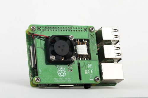
Anatomy of a product quality issue: PoE HAT
Reading Time: 5 minutesOne of the neat new features of the Raspberry Pi 3 Model B+ is its support for IEEE 802.3af Power-over-Ethernet (PoE). This standard allows up to 13W of power to be delivered over the twisted pairs in an Ethernet cable without interfering with the transmission of data. The Raspberry Pi board itself…
-

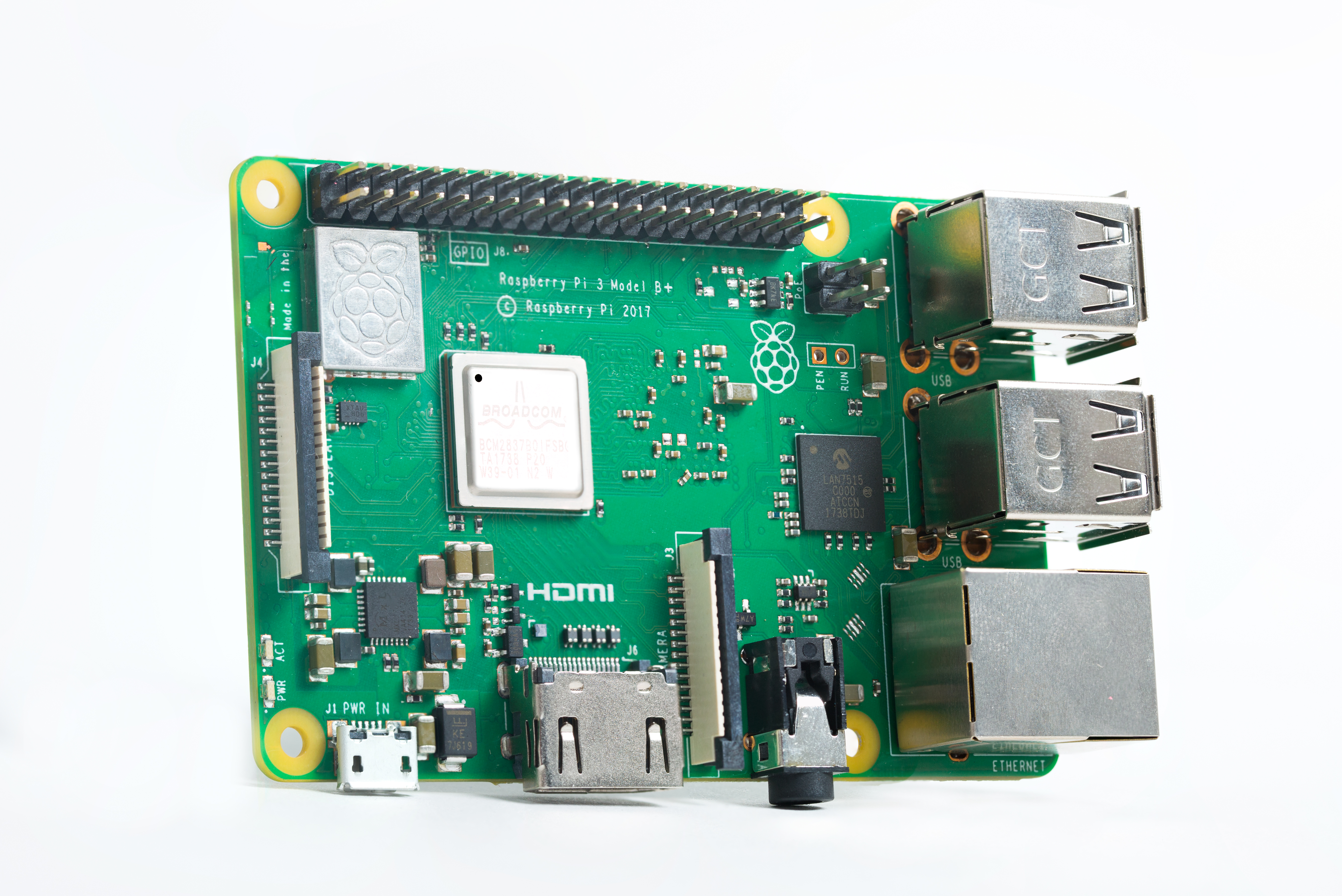
More power to your Pi
Reading Time: 9 minutesIt’s been just over three weeks since we launched the new Raspberry Pi 3 Model B+. Although the product is branded Raspberry Pi 3B+ and not Raspberry Pi 4, a serious amount of engineering was involved in creating it. The wireless networking, USB/Ethernet hub, on-board power supplies, and BCM2837 chip were all…