More power to your Pi
It’s been just over three weeks since we launched the new Raspberry Pi 3 Model B+. Although the product is branded Raspberry Pi 3B+ and not Raspberry Pi 4, a serious amount of engineering was involved in creating it. The wireless networking, USB/Ethernet hub, on-board power supplies, and BCM2837 chip were all upgraded: together these represent almost all the circuitry on the board! Today, I’d like to tell you about the work that has gone into creating a custom power supply chip for our newest computer.
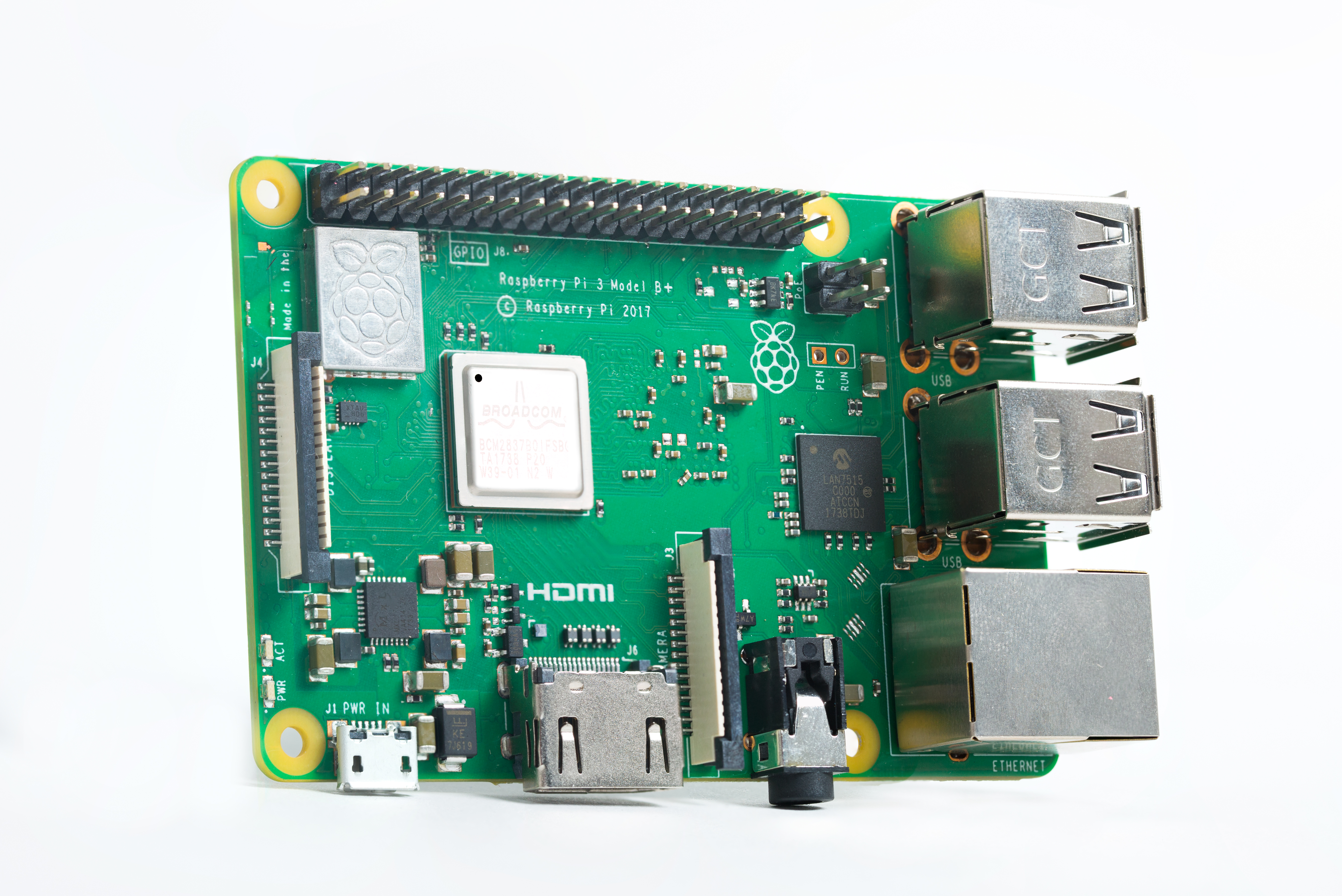
The new Raspberry Pi 3B+, sporting a new, custom power supply chip (bottom left-hand corner)
Successful launch
The Raspberry Pi 3B+ has been well received, and we’ve enjoyed hearing feedback from the community as well as reading the various reviews and articles highlighting the solid improvements in wireless networking, Ethernet, CPU, and thermal performance of the new board. Gareth Halfacree’s post here has some particularly nice graphs showing the increased performance as well as how the Pi 3B+ keeps cool under load due to the new CPU package that incorporates a metal heat spreader. The Raspberry Pi production lines at the Sony UK Technology Centre are running at full speed, and it seems most people who want to get hold of the new board are able to find one in stock.
Powering your Pi
One of the most critical but often under-appreciated elements of any electronic product, particularly one such as Raspberry Pi with lots of complex on-board silicon (processor, networking, high-speed memory), is the power supply. In fact, the Raspberry Pi 3B+ has no fewer than six different voltage rails: two at 3.3V — one special ‘quiet’ one for audio, and one for everything else; 1.8V; 1.2V for the LPDDR2 memory; and 1.2V nominal for the CPU core. Note that the CPU voltage is actually raised and lowered on the fly as the speed of the CPU is increased and decreased depending on how hard the it is working. The sixth rail is 5V, which is the master supply that all the others are created from, and the output voltage for the four downstream USB ports; this is what the mains power adaptor is supplying through the micro USB power connector.
Power supply primer
There are two common classes of power supply circuits: linear regulators and switching regulators. Linear regulators work by creating a lower, regulated voltage from a higher one. In simple terms, they monitor the output voltage against an internally generated reference and continually change their own resistance to keep the output voltage constant. Switching regulators work in a different way: they ‘pump’ energy by first storing the energy coming from the source supply in a reactive component (usually an inductor, sometimes a capacitor) and then releasing it to the regulated output supply. The switches in switching regulators effect this energy transfer by first connecting the inductor (or capacitor) to store the source energy, and then switching the circuit so the energy is released to its destination.
Linear regulators produce smoother, less noisy output voltages, but they can only convert to a lower voltage, and have to dissipate energy to do so. The higher the output current and the voltage difference across them is, the more energy is lost as heat. On the other hand, switching supplies can, depending on their design, convert any voltage to any other voltage and can be much more efficient (efficiencies of 90% and above are not uncommon). However, they are more complex and generate noisier output voltages.
Designers use both types of regulators depending on the needs of the downstream circuit: for low-voltage drops, low current, or low noise, linear regulators are usually the right choice, while switching regulators are used for higher power or when efficiency of conversion is required. One of the simplest switching-mode power supply circuits is the buck converter, used to create a lower voltage from a higher one, and this is what we use on the Pi.
A history lesson
The BCM2835 processor chip (found on the original Raspberry Pi Model B and B+, as well as on the Zero products) has on-chip power supplies: one switch-mode regulator for the core voltage, as well as a linear one for the LPDDR2 memory supply. This meant that in addition to 5V, we only had to provide 3.3V and 1.8V on the board, which was relatively simple to do using cheap, off-the-shelf parts.
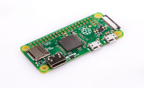
Pi Zero sporting a BCM2835 processor which only needs 2 external switchers (the components clustered behind the camera port)
When we moved to the BCM2836 for Raspberry Pi Model 2 (and subsequently to the BCM2837A1 and B0 for Raspberry Pi 3B and 3B+), the core supply and the on-chip LPDDR2 memory supply were not up to the job of supplying the extra processor cores and larger memory, so we removed them. (We also used the recovered chip area to help fit in the new quad-core ARM processors.) The upshot of this was that we had to supply these power rails externally for the Raspberry Pi 2 and models thereafter. Moreover, we also had to provide circuitry to sequence them correctly in order to control exactly when they power up compared to the other supplies on the board.
Power supply design is tricky (but critical)
Raspberry Pi boards take in 5V from the micro USB socket and have to generate the other required supplies from this. When 5V is first connected, each of these other supplies must ‘start up’, meaning go from ‘off’, or 0V, to their correct voltage in some short period of time. The order of the supplies starting up is often important: commonly, there are structures inside a chip that form diodes between supply rails, and bringing supplies up in the wrong order can sometimes ‘turn on’ these diodes, causing them to conduct, with undesirable consequences. Silicon chips come with a data sheet specifying what supplies (voltages and currents) are needed and whether they need to be low-noise, in what order they must power up (and in some cases down), and sometimes even the rate at which the voltages must power up and down.

A Pi3. Power supply components are clustered bottom left next to the micro USB, middle (above LPDDR2 chip which is on the bottom of the PCB) and above the A/V jack.
In designing the power chain for the Pi 2 and 3, the sequencing was fairly straightforward: power rails power up in order of voltage (5V, 3.3V, 1.8V, 1.2V). However, the supplies were all generated with individual, discrete devices. Therefore, I spent quite a lot of time designing circuitry to control the sequencing — even with some design tricks to reduce component count, quite a few sequencing components are required. More complex systems generally use a Power Management Integrated Circuit (PMIC) with multiple supplies on a single chip, and many different PMIC variants are made by various manufacturers. Since Raspberry Pi 2 days, I was looking for a suitable PMIC to simplify the Pi design, but invariably (and somewhat counter-intuitively) these were always too expensive compared to my discrete solution, usually because they came with more features than needed.
One device to rule them all
It was way back in May 2015 when I first chatted to Peter Coyle of Exar (Exar were bought by MaxLinear in 2017) about power supply products for Raspberry Pi. We didn’t find a product match then, but in June 2016 Peter, along with Tuomas Hollman and Trevor Latham, visited to pitch the possibility of building a custom power management solution for us.
I was initially sceptical that it could be made cheap enough. However, our discussion indicated that if we could tailor the solution to just what we needed, it could be cost-effective. Over the coming weeks and months, we honed a specification we agreed on from the initial sketches we’d made, and Exar thought they could build it for us at the target price.
The chip we designed would contain all the key supplies required for the Pi on one small device in a cheap QFN package, and it would also perform the required sequencing and voltage monitoring. Moreover, the chip would be flexible to allow adjustment of supply voltages from their default values via I2C; the largest supply would be capable of being adjusted quickly to perform the dynamic core voltage changes needed in order to reduce voltage to the processor when it is idling (to save power), and to boost voltage to the processor when running at maximum speed (1.4 GHz). The supplies on the chip would all be generously specified and could deliver significantly more power than those used on the Raspberry Pi 3. All in all, the chip would contain four switching-mode converters and one low-current linear regulator, this last one being low-noise for the audio circuitry.
The MXL7704 chip
The project was a great success: MaxLinear delivered working samples of first silicon at the end of May 2017 (almost exactly a year after we had kicked off the project), and followed through with production quantities in December 2017 in time for the Raspberry Pi 3B+ production ramp.

Front row: Roger with the very first Pi 3B+ prototypes and James with a MXL7704 development board hacked to power a Pi 3. Back row left to right: Will Torgerson, Trevor Latham, Peter Coyle, Tuomas Hollman.
The MXL7704 device has been key to reducing Pi board complexity and therefore overall bill of materials cost. Furthermore, by being able to deliver more power when needed, it has also been essential to increasing the speed of the (newly packaged) BCM2837B0 processor on the 3B+ to 1.4GHz. The result is improvements to both the continuous output current to the CPU (from 3A to 4A) and to the transient performance (i.e. the chip has helped to reduce the ‘transient response’, which is the change in supply voltage due to a sudden current spike that occurs when the processor suddenly demands a large current in a few nanoseconds, as modern CPUs tend to do).
With the MXL7704, the power supply circuitry on the 3B+ is now a lot simpler than the Pi 3B design. This new supply also provides the LPDDR2 memory voltage directly from a switching regulator rather than using linear regulators like the Pi 3, thereby improving energy efficiency. This helps to somewhat offset the extra power that the faster Ethernet, wireless networking, and processor consume. A pleasing side effect of using the new chip is the symmetric board layout of the regulators — it’s easy to see the four switching-mode supplies, given away by four similar-looking blobs (three grey and one brownish), which are the inductors.
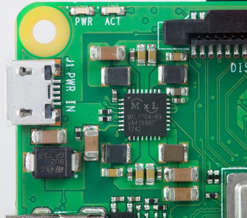
The Pi 3B+ PMIC MXL7704 — pleasingly symmetric
Kudos
It takes a lot of effort to design a new chip from scratch and get it all the way through to production — we are very grateful to the team at MaxLinear for their hard work, dedication, and enthusiasm. We’re also proud to have created something that will not only power Raspberry Pis, but will also be useful for other product designs: it turns out when you have a low-cost and flexible device, it can be used for many things — something we’re fairly familiar with here at Raspberry Pi! For the curious, the product page (including the data sheet) for the MXL7704 chip is here. Particular thanks go to Peter Coyle, Tuomas Hollman, and Trevor Latham, and also to Jon Cronk, who has been our contact in the US and has had to get up early to attend all our conference calls!

The MXL7704 design team celebrating on Pi Day — it takes a lot of people to design a chip!
I hope you liked reading about some of the effort that has gone into creating the new Pi. It’s nice to finally have a chance to tell people about some of the (increasingly complex) technical work that makes building a $35 computer possible — we’re very pleased with the Raspberry Pi 3B+, and we hope you enjoy using it as much as we’ve enjoyed creating it!
Website: LINK