Schlagwort: open source
-

The 2024 Arduino Open Source Report is here!
Reading Time: 2 minutesEvery year, we take a moment to reflect on the contributions we made to the open source movement, and the many ways our community has made a huge difference. As we publish the latest Open Source Report, we are proud to say 2024 was another year of remarkable progress and achievements. A year…
-

The 2023 Arduino Open Source Report is out
Reading Time: 2 minutesNew year, new Open Source Report! Lots has happened in 2023 in terms of open-source development, and we’re excited to share our yearly recap of the various contributions from the Arduino team and the community. Together, we have released new, important open-source projects – both hardware and software – as well as…
-

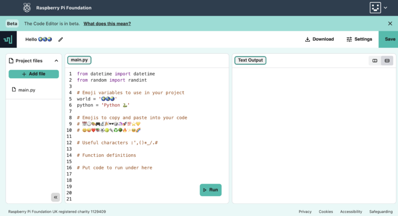
Our Code Editor is open source
Reading Time: 5 minutesA couple of months ago we announced that you can test the online text-based Code Editor we’re building to help young people aged 7 and older learn to write code. Now we’ve made the code for the Editor open source so people can repurpose and contribute to it. How can you use…
-
The 2022 Arduino Open Source Report is out
Reading Time: 2 minutesIn our last annual report we described 2021 as one of the busiest and most productive years in Arduino history in terms of open source development (if you missed that report, go read it now as it contains so many nice things). Well, we didn’t rest in 2022 either! The Arduino team…
-
The 2021 Arduino Open Source Report is out
Reading Time: 2 minutesArduino Team — January 13th, 2022 We’re excited to announce the Arduino Open Source Report for 2021 is now available, offering many insights into the development of our open-source ecosystem during the past year. In this retrospective report you’ll learn about the activities Arduino carried out in the last twelve months, thanks…
-

Get your SteFly™ – Nice sightseeing tour of Pavullo city
Reading Time: < 1 minuteNice sightseeing tour of Pavullo city during the traffic pattern. At the last competition day of the 1st e-glide contest it was very difficult to get back home to the airfield. The finish cylinder was big enough to stay out of the rain shower and still finish the task. With a…
-

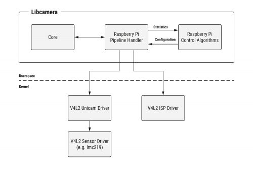
An open source camera stack for Raspberry Pi using libcamera
Reading Time: 6 minutesSince we released the first Raspberry Pi camera module back in 2013, users have been clamouring for better access to the internals of the camera system, and even to be able to attach camera sensors of their own to the Raspberry Pi board. Today we’re releasing our first version of a new…
-
Hands-on with the Arduino CLI!
Reading Time: < 1 minuteHands-on with the Arduino CLI! Arduino Team — April 23rd, 2020 In our last post, we told you that the Arduino CLI’s primary goal is to provide a flexible yet simple command line tool with all the features and ease of use that made Arduino a successful platform, and enable users…
-

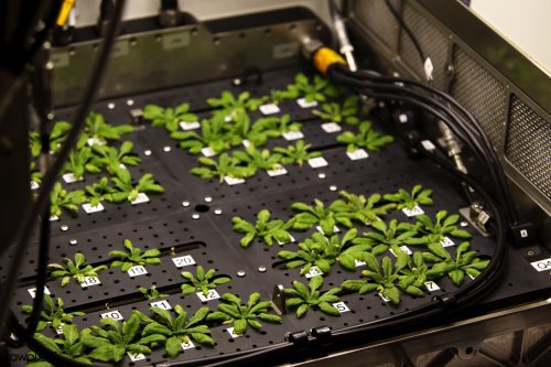
Growth Monitor pi: an open monitoring system for plant science
Reading Time: 3 minutesPlant scientists and agronomists use growth chambers to provide consistent growing conditions for the plants they study. This reduces confounding variables – inconsistent temperature or light levels, for example – that could render the results of their experiments less meaningful. To make sure that conditions really are consistent both within and between…
-

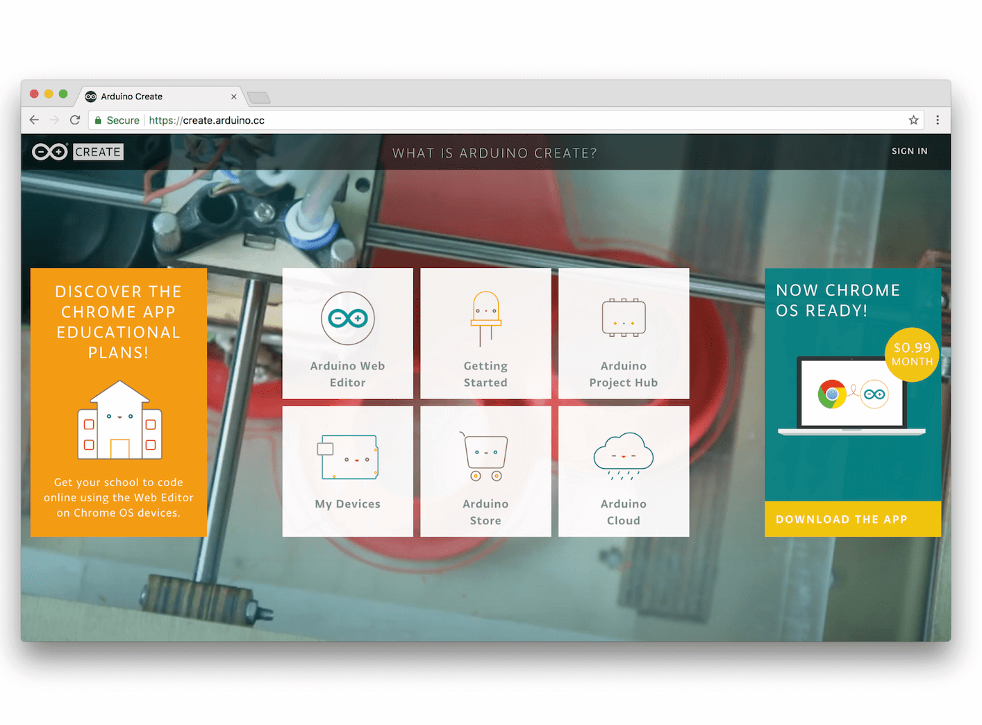
You can now use Arduino to program Linux IoT devices
Reading Time: 2 minutesYou can now use Arduino to program Linux IoT devices Arduino Team — March 13th, 2018 Today, at Embedded Linux Conference 2018, Arduino announced the expansion of the number of architectures supported by its Arduino Create platform for the development of IoT applications. With this new release, Arduino Create users can manage…
-

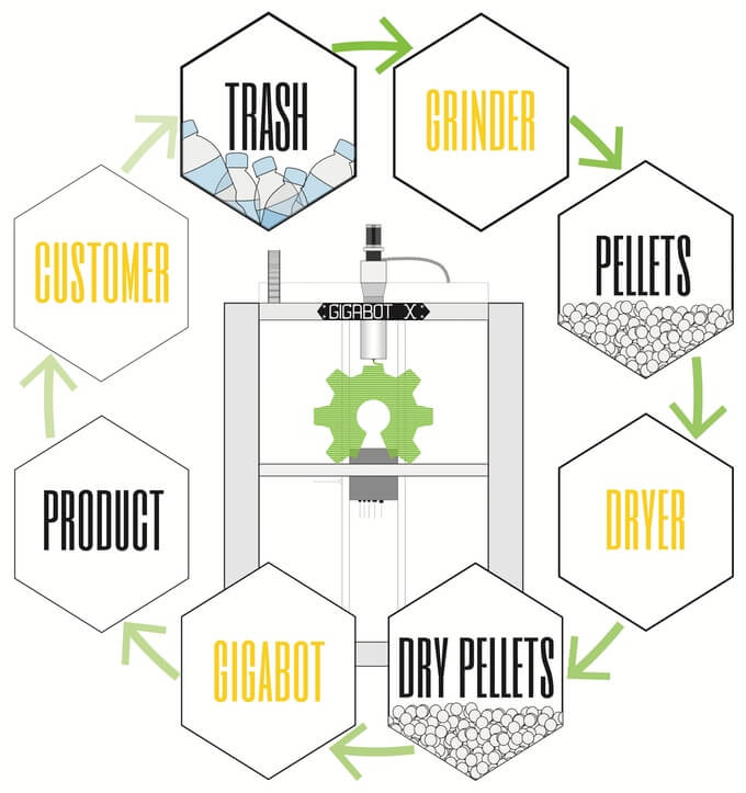
Gigabot X can 3D Print with Recycled Plastic Pellets
Reading Time: 3 minutesNow live on Kickstarter is the Gigabot X, a large-scale, direct pellet extrusion 3D printer for fabricating with recycled plastic. Houston, Texas might seem likely an unlikely location for a revolution in 3D printing, but this is where re:3d have announced the Gigabot X, an open source 3D printer that fabricates with…
-

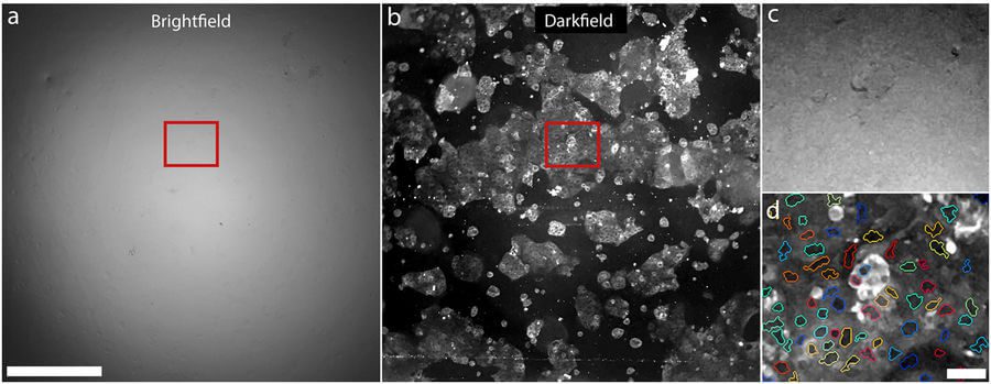
Open Source 3D Printed Clip-On Microscope For Smartphones
Reading Time: 3 minutesThis is an open source design for a smartphone camera microscope which can be customized, downloaded and 3D printed. A team of researchers at RMIT University in Australia have developed a 3D printable clip-on microscope for smartphones. The design of the microscope has been shared on the Centre for Nanoscale BioPhotonics website.…
-

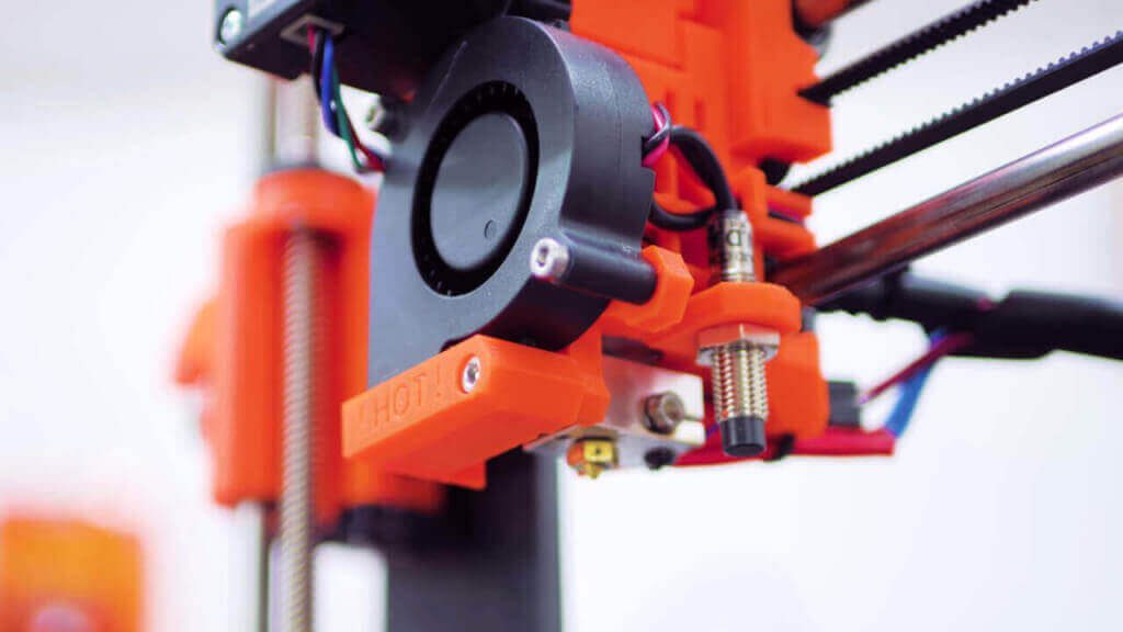
Original Prusa i3 MK2 Review: It Doesn’t Get Any Better
Reading Time: 13 minutesThis is where 3D printing is right now, according to Thomas Sanladerer. Read his detailed and enthusiastic Original Prusa i3 MK2 review. Don’t miss: Best Prusa i3 Clone – 24 Prusa i3 Kits vs Prusa i3 MK2 Editor’s Note: This content originally appeared on Thomas Sanladerer’s YouTube Channel and is licensed as…
-

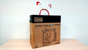
Building the Original Prusa i3 MK3: Review the Facts Here!
Reading Time: 2 minutesSo what’s the big deal about the Original Prusa i3 MK3? It’s pitched as a refinement of everything Prusa Research have achieved to date; more than a reliability upgrade, but a new and improved desktop 3D printer with some awesome new features. Where the previous model offered astonishing print quality for the…
-

Ultimate 3D printer control with OctoPrint
Reading Time: 3 minutesControl and monitor your 3D printer remotely with a Raspberry Pi and OctoPrint. Timelapse of OctoPrint Ornament Printed on a bq Witbox STL file can be found here: http://www.thingiverse.com/thing:191635 OctoPrint is located here: http://www.octoprint.org 3D printing Whether you have a 3D printer at home or use one at your school or local…