Schlagwort: Nano Every
-

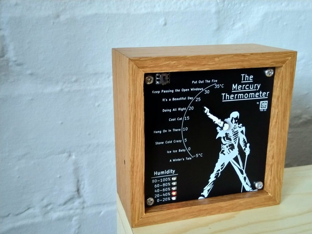
Freddie points to the current temperature on the Mercury Thermometer
Reading Time: 2 minutesArduino Team — June 16th, 2022 Nearly everyone is familiar with the mercury thermometer and how it uses the expansion of the element to display ambient temperatures. But in Instructables member TurboSnail’s latest project, they attempted to turn this concept on its head by making a thermometer that uses the iconic Freddie Mercury to show the…
-

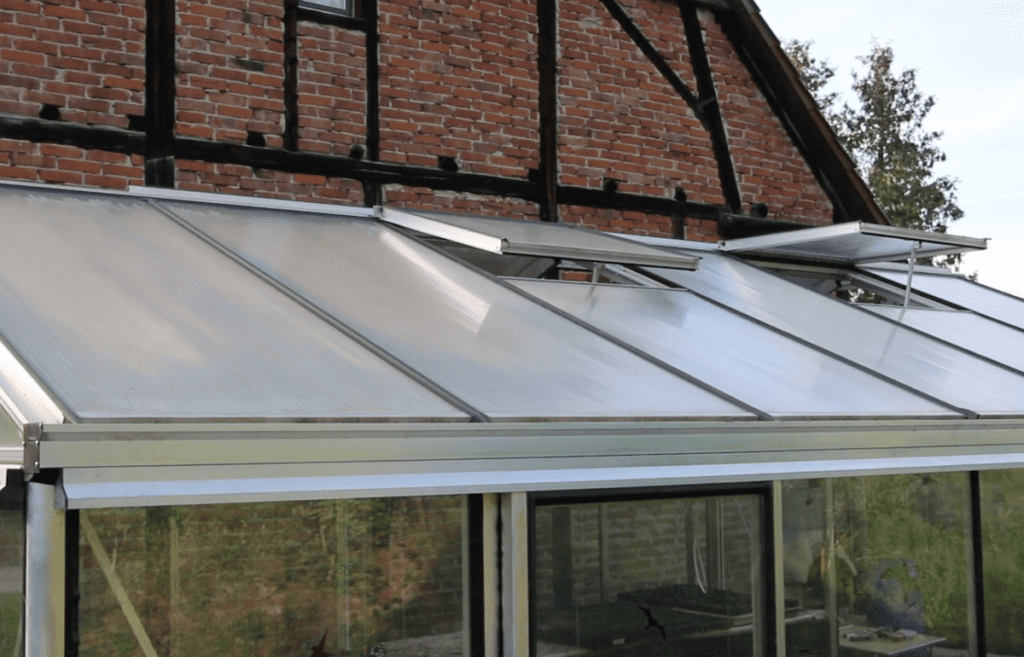
Automated window system helps keep the greenhouse climate regulated
Reading Time: 2 minutesArduino Team — June 9th, 2022 Greenhouses are excellent ways to grow plants due to their compact nature and the fact that they can absorb and store the sun’s light as heat to keep their internal temperature higher than outside. But when it comes to adding ventilation for cooling things down, decreasing…
-

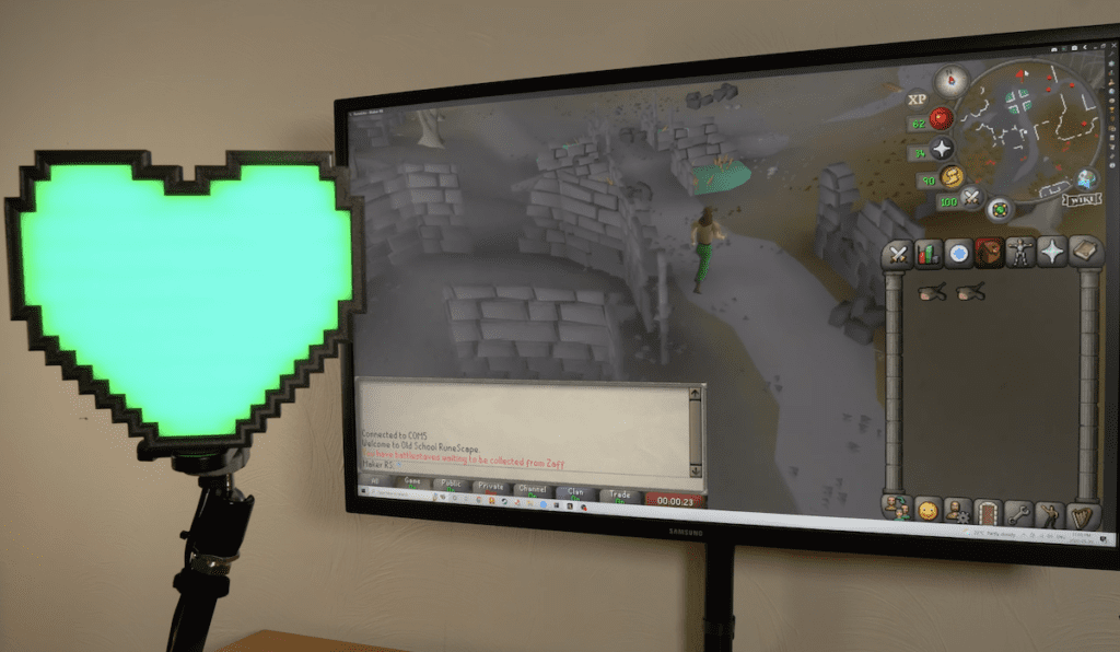
A real-world health bar for Old School RuneScape
Reading Time: 2 minutesArduino Team — June 3rd, 2022 For those of us of a certain age, RuneScape provides a deep sense of nostalgia. The original RuneScape MMORPG died off in popularity many years ago, but Old School RuneScape, which launched in 2013, recently gained traction once again. As with most MMORPGs, Old School RuneScape…
-

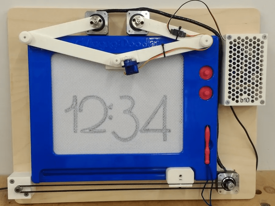
Sketch the current time with this Magna Doodle clock
Reading Time: 2 minutesArduino Team — May 31st, 2022 The Magna Doodle is a classic children’s toy that works by embedding a layer of iron shavings just below the surface of a canvas and then using a magnetic pen to pull them up, thus showing whatever lines might have been drawn. Steve Turner had the…
-

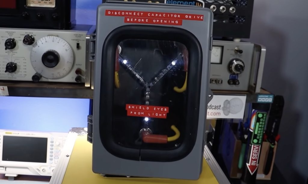
Great Scott! Learn how to drive flux capacitor-style LEDs
Reading Time: 2 minutesArduino Team — April 14th, 2022 The flux capacitor is one of the most iconic movie props of all time. Part of that is due to its plot purpose in the Back to the Future franchise, but its fame is also because it looked so futuristic when the first movie hit theaters…
-

Reimagining the lamp with an intelligent, floating bulb
Reading Time: 2 minutesArduino Team — March 9th, 2022 The humble lamp can come in many different forms, but nearly all of them feature a singular bulb that is uninspired and only responds to a light switch or potentially an app. YouTuber Tom Ouwerkerk, on the other hand, has designed a creative light accessory that is entirely…
-

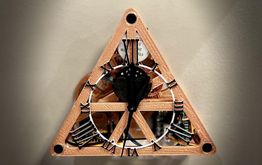
This 3D-printed, three-sided clock tells time with three hands
Reading Time: 2 minutesArduino Team — February 9th, 2022 Back in April 2021, Instructables user saulemmetquinn had the idea to build a fully 3D-printed clock that was based on the Triangulum constellation, which as the name implies, is a triangle. But it wouldn’t only tell the time using the typical set of hands and numbers, but also the current…
-
Supplino is a variable benchtop power supply that you can build yourself
Reading Time: 2 minutesArduino Team — January 20th, 2022 Working with electronics requires access to stable power in a variety of voltages. Some components require 3.3V and others require 5V. Still others need 9V or 12V — there are many possibilities. You could keep a variety of wall warts on hand, but a variable benchtop…
-

Working Eye of Agamotto from Doctor Strange (excluding time travel)
Reading Time: 2 minutesArduino Team — August 25th, 2021 We’ve not released a time travel shield for Arduino yet. But when we do, this Eye of Agamotto project will be a perfect fit. So even though it may not bend time yet, it does everything else we’ve seen in Doctor Strange. Eye of Arduino. Er……
-
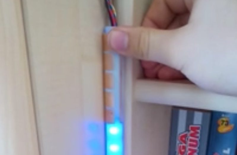
Watch your music come to life on this single LED strip audio spectrum visualizer
Reading Time: 2 minutesArduino Team — July 17th, 2021 While thinking of an interesting project to create, Hackster user marcaubin started to imagine an audio spectrum visualizer, but not a traditional one that has a matrix of LEDs with columns corresponding to certain frequencies. Instead, his device would have just a single vertical NeoPixel strip featuring 29…
-

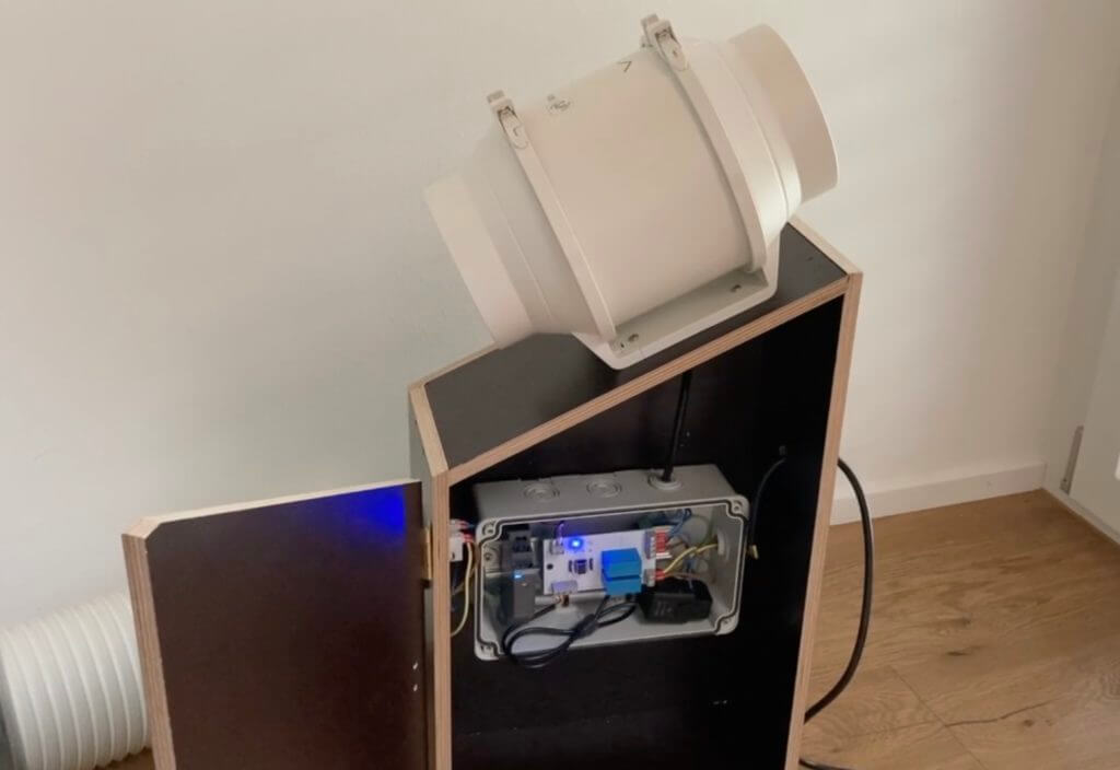
Extending a mobile AC unit’s exhaust duct with an air extractor
Reading Time: 2 minutesExtending a mobile AC unit’s exhaust duct with an air extractor Arduino Team — June 4th, 2021 Portable air conditioners are amazing, especially as we head into the hot summer months. But one big downside is having to place them close to a window that will fit the guard, otherwise it’s really…
-
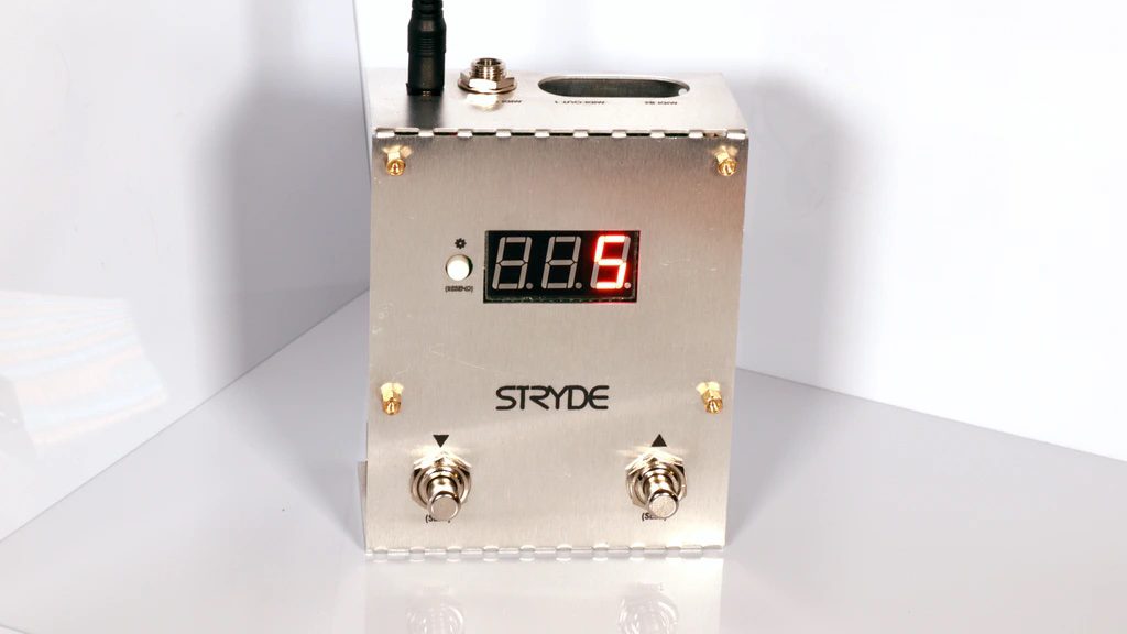
Stryde is an Arduino Nano Every-powered MIDI preset loader
Reading Time: 2 minutesArduino Team — May 23rd, 2021 MIDI-controlled instruments are awesome, as custom sounds can be loaded and dynamically changed while you play. However, accessing these effects often requires an external controller that can get expensive and complicated. That is why music enthusiast Joe King created the Stryde, which is a fully integrated…
-

LOPES helps prioritize your tasks with LEDs
Reading Time: < 1 minuteArduino Team — April 12th, 2021 As spotted on Reddit, the Light Based Optical Productivity Enhancement System (LOPES) is an Arduino Nano Every-powered device that lights up depending on the tasks that you have left to complete. The Nano takes input from five copper touch sensor plates on the top, which…
-

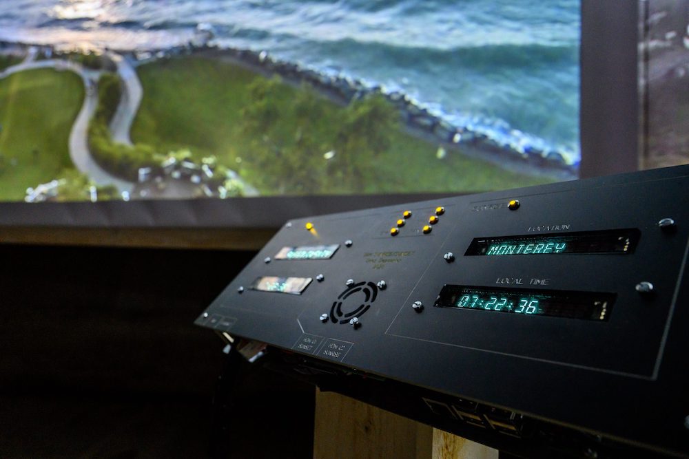
Dries Depoorter’s installation displays real-time sunsets and sunrises via unsecured CCTV cameras
Reading Time: 2 minutesDries Depoorter’s installation displays real-time sunsets and sunrises via unsecured CCTV cameras Arduino Team — August 19th, 2020 Sunrises can be beautiful, not to mention sunsets, but seeing both at one time would seem to be an impossibility. Dries Depoorter, however, has developed an installation that displays the two events as they happen on…
-

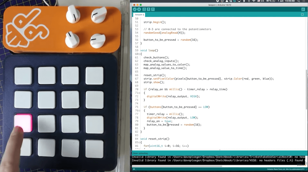
Dave Darko designs a 16-button keep-alive switch with a Nano Every
Reading Time: < 1 minuteDave Darko designs a 16-button keep-alive switch with a Nano Every Arduino Team — July 29th, 2020 It’s generally not advisable to leave equipment running when unattended. As a safeguard against this possibility at hackerspaces and elsewhere, element14 Presents’ Dave Darko built a custom switch that requires users to intermittently push a button…
-

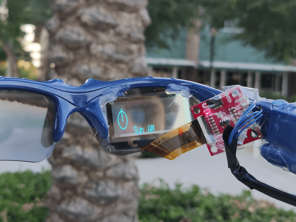
Student designs his own pair of smart glasses with a transparent OLED display and Arduino Nano Every
Reading Time: < 1 minuteStudent designs his own pair of smart glasses with a transparent OLED display and Arduino Nano Every Arduino Team — July 24th, 2020 For his school science fair, Mars Kapadia decided to take things up a notch and create his own pair of smart glasses. The wearable device, which went on to…
-

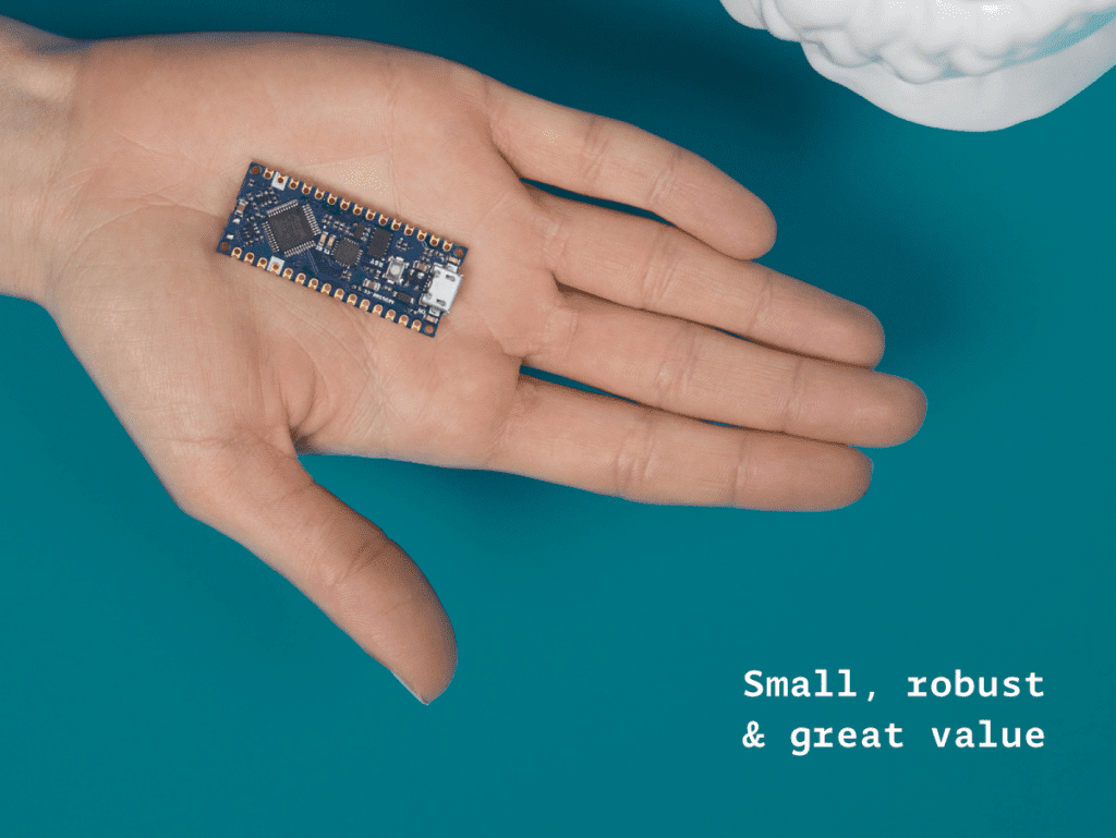
Getting started with the new Arduino Nano Every
Reading Time: 4 minutesThe original Arduino Nano occupies a special place in many makers’ hearts. The tiny footprint (48×18 mm – around half a stick of gum), reliability and tons of examples makes the Nano perfect for wearables, drones — in fact any project made to last. The Nano is back! The new entry-level Arduino…