In many respects we think of artificial intelligence as being all encompassing. One AI will do any task we ask of it. But in reality, even when AI reaches the advanced levels we envision, it won’t automatically be able to do everything. The Fraunhofer Institute for Microelectronic Circuits and Systems has been giving this a lot of thought.
AI gesture training
Okay, so you’ve got an AI. Now you need it to learn the tasks you want it to perform. Even today this isn’t an uncommon exercise. But the challenge that Fraunhofer IMS set itself was training an AI without any additional computers.
As a test case, an Arduino Nano 33 BLE Sense was employed to build a demonstration device. Using only the onboard 9-axis motion sensor, the team built an untethered gesture recognition controller. When a button is pressed, the user draws a number in the air, and corresponding commands are wirelessly sent to peripherals. In this case, a robotic arm.
At first glance this might not seem overly advanced. But consider that it’s running entirely from the device, with just a small amount of memory and an Arduino Nano. Fraunhofer IMS calls this “embedded intelligence,” as it’s not the robot arms that’s clever, but the controller itself.
This is achieved when training the device using a “feature extraction” algorithm. When the gesture is executed, the artificial neural network (ANN) is able to pick out only the relevant information. This allows for impressive data reduction and a very efficient, compact AI.
Obviously this is just an example use case. It’s easy to see the massive potential that this kind of compact, learning AI could have. Whether it’s in edge control, industrial applications, wearables or maker projects. If you can train a device to do the job you want, it can offer amazing embedded intelligence with very few resources.
In this deep dive article, performance optimization specialist Larry Bank (a.k.a The Performance Whisperer) takes a look at the work he did for the Arduino team on the latest version of the Arduino_OV767x library.
Arduino recently announced an update to the Arduino_OV767x camera library that makes it possible to run machine vision using TensorFlow Lite Micro on your Arduino Nano 33 BLE board.
If you just want to try this and run machine learning on Arduino, you can skip to the project tutorial.
The rest of this article is going to look at some of the lower level optimization work that made this all possible. There are higher performance industrial-targeted options like the Arduino Portenta available for machine vision, but the Arduino Nano 33 BLE has sufficient performance with TensorFlow Lite Micro support ready in the Arduino IDE. Combined with an OV767x module makes a low-cost machine vision solution for lower frame-rate applications like the person detection example in TensorFlow Lite Micro.
Need for speed
Recent optimizations done by Google and Arm to the CMSIS-NN library also improved the TensorFlow Lite Micro inference speed by over 16x, and as a consequence bringing down inference time from 19 seconds to just 1.2 seconds on the Arduino Nano 33 BLE boards. By selecting the person_detection example in the Arduino_TensorFlowLite library, you are automatically including CMSIS-NN underneath and benefitting from these optimizations. The only difference you should see is that it runs a lot faster!
The CMSIS-NN library provides optimized neural network kernel implementations for all Arm’s Cortex-M processors, ranging from Cortex-M0 to Cortex-M55. The library utilizes the processor’s capabilities, such as DSP and M-Profile Vector (MVE) extensions, to enable the best possible performance.
The Arduino Nano 33 BLE board is powered by Arm Cortex-M4, which supports DSP extensions. That will enable the optimized kernels to perform multiple operations in one cycle using SIMD (Single Instruction Multiple Data) instructions. Another optimization technique used by the CMSIS-NN library is loop unrolling. These techniques combined will give us the following example where the SIMD instruction, SMLAD (Signed Multiply with Addition), is used together with loop unrolling to perform a matrix multiplication y=a*b, where
a=[1,2]
and
b=[3,5 4,6]
a, b are 8-bit values and y is a 32-bit value. With regular C, the code would look something like this:
However, using loop unrolling and SIMD instructions, the loop will end up looking like this:
a_operand = a[0] | a[1] << 16 // put a[0], a[1] into one variable
  for(i=0; i<2; ++i)
    b_operand = b[0][i] | b[1][i] << 16 // vice versa for b
    y[i] = __SMLAD(a_operand, b_operand, y[i])
This code will save cycles due to
fewer for-loop checks
__SMLAD performs two multiply and accumulate in one cycle
This is a simplified example of how two of the CMSIS-NN optimization techniques are used.
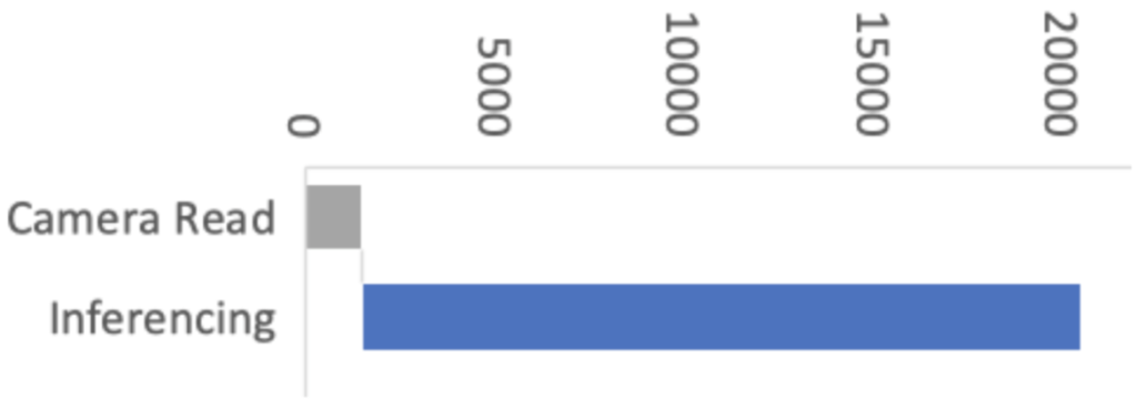
Figure 1: Performance with initial versions of libraries
Figure 2: Performance with CMSIS-NN optimizations
This improvement means the image acquisition and preprocessing stages now have a proportionally bigger impact on machine vision performance. So in Arduino our objective was to improve the overall performance of machine vision inferencing on Arduino Nano BLE sense by optimizing the Arduino_OV767X library while maintaining the same library API, usability and stability.
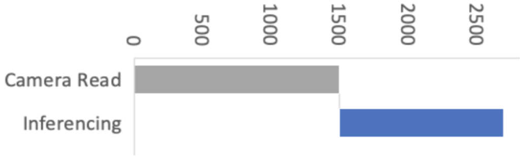
Figure 3: Performance with CMSIS-NN and camera library optimizations
For this, we enlisted the help of Larry Bank who specializes in embedded software optimization. Larry’s work got the camera image read down from 1500ms to just 393ms for a QCIF (176×144 pixel) image. This was a great improvement!
Let’s have a look at how Larry approached the camera library optimization and how some of these techniques can apply to your Arduino code in general.
Performance optimizing Arduino code
It’s rarely practical or necessary to optimize every line of code you write. In fact there are very good reasons to prioritize readable, maintainable code. Being readable and optimized don’t necessarily have to be mutually exclusive. However, embedded systems have constrained resources, and when applications demand more performance, some trade-offs might have to be made. Sometimes it is necessary to restructure algorithms, pay attention to compiler behavior, or even analyze timing of machine code instructions in order to squeeze the most out of a microcontroller. In some cases this can make the code less readable — but the beauty of an Arduino library is that this can be abstracted (hidden) from user sketch code beneath the cleaner library function APIs.
What does “Camera.readFrame” do?
We’ve connected a camera to the Arduino. The Arduino_OV767X library sets up the camera and lets us transfer the raw image data from the camera into the Arduino Nano BLE memory. The smallest resolution setting, QCIF, is 176 x 144 pixels. Each pixel is encoded in 2 bytes. We therefore need to transfer at least 50688 bytes (176 x 144 x 2 ) every time we capture an image with Camera.readFrame. Because the function is performing a byte read operation over 50 thousand times per frame, the way it’s implemented has a big impact on performance. So let’s have a look at how we can most efficiently connect the camera to the Arduino and read a byte of data from it.
Philosophy
I tend to see the world of code through the “lens” of optimization. I’m not advocating for everyone to share my obsession with optimization. However, when it does become necessary, it’s helpful to understand details of the target hardware and CPU. What I often encounter with my clients is that their code implements their algorithm neatly and is very readable, but it’s not necessarily ‘performance friendly’ to the target machine. I assume this is because most people see code from a top-down approach: they think in terms of the abstract math and how to process the data. My history in working with very humble machines and later turning that into a career has flipped that narrative on its head. I see software from the bottom up: I think about how the memory, I/O and CPU registers interact to move and process the data used by the algorithm. It’s often possible to make dramatic improvements to the code execution speed without losing any of its readability. When your readable/maintainable solution still isn’t fast enough, the next phase is what I call ‘uglification.’ This involves writing code that takes advantage of specific features of the CPU and is nearly always more difficult to follow (at least at first glance!).
Optimization methodology
Optimization is an iterative process. I usually work in this order:
Test assumptions in the algorithm (sometimes requires tracing the data)
Make innocuous changes in the logic to better suit the CPU (e.g. change modulus to logical AND)
Flatten the hierarchy or simplify overly nested classes/structures
Test any slow/fast paths (aka statistics of the data — e.g. is 99% of the incoming data 0?)
Go back to the author(s) and challenge their decisions on data precision / storage
Make the code more suitable for the target architecture (e.g. 32 vs 64-bit CPU registers)
If necessary (and permitted by the client) use intrinsics or other CPU-specific features
Go back and test every assumption again
If you would like to investigate this topic further, I’ve written a more detailed presentation on Writing Performant C++ code.
Depending on the size of the project, sometimes it’s hard to know where to start if there are too many moving parts. If a profiler is available, it can help narrow the search for the “hot spots” or functions which are taking the majority of the time to do their work. If no profiler is available, then I’ll usually use a time function like micros() to read the current tick counter to measure execution speed in different parts of the code. Here is an example of measuring absolute execution time on Arduino:
long lTime;
  lTime = micros();
  <do the work>
  iTime = micros() - lTime;
  Serial.printf(“Time to execute xxx = %d microseconds\n”, (int)lTime);
I’ve also used a profiler for my optimization work with OpenMV. I modified the embedded C code to run as a MacOS command line app to make use of the excellent XCode Instruments profiler. When doing that, it’s important to understand how differently code executes on a PC versus embedded — this is mostly due to the speed of the CPU compared to the speed of memory.
Pins, GPIO and PORTs
One of the most powerful features of the Arduino platform is that it presents a consistent API to the programmer for accessing hardware and software features that, in reality, can vary greatly across different target architectures. For example, the features found in common on most embedded devices like GPIO pins, I2C, SPI, FLASH, EEPROM, RAM, etc. have many diverse implementations and require very different code to initialize and access them.
Let’s look at the first in our list, GPIO (General Purpose Input/Output pins). On the original Arduino Uno (AVR MCU), the GPIO lines are arranged in groups of 8 bits per “PORT” (it’s an 8-bit CPU after all) and each port has a data direction register (determines if it’s configured for input or output), a read register and a write register. The newer Arduino boards are all built around various Arm Cortex-M microcontrollers. These MCUs have GPIO pins arranged into groups of 32-bits per “PORT” (hmm – it’s a 32-bit CPU, I wonder if that’s the reason). They have a similar set of control mechanisms, but add a twist — they include registers to SET or CLR specific bits without disturbing the other bits of the port (e.g. port->CLR = 1; will clear GPIO bit 0 of that port). From the programmer’s view, Arduino presents a consistent set of functions to access these pins on these diverse platforms (clickable links below to the function definitions on Arduino.cc):
For me, this is the most powerful idea of Arduino. I can build and deploy my code to an AVR, a Cortex-M, ESP8266 or an ESP32 and not have to change a single line of code nor maintain multiple build scripts. In fact, in my daily work (both hobby and professional), I’m constantly testing my code on those 4 platforms. For example, my LCD/OLED display library (OneBitDisplay) can control various monochrome LCD and OLED displays and the same code runs on all Arduino boards and can even be built on Linux.
One downside to having these ‘wrapper’ functions hide the details of the underlying implementation is that performance can suffer. For most projects it’s not an issue, but when you need to get every ounce of speed out of your code, it can make a huge difference.
Camera data capture
One of the biggest challenges of this project was that the original OV7670 library was only able to run at less than 1 frame per second (FPS) when talking to the Nano 33. The reason for the low data rate is that the Nano 33 doesn’t expose any hardware which can directly capture the parallel image data, so it must be done ‘manually’ by testing the sync signals and reading the data bits through GPIO pins (e.g. digitalRead) using software loops. The Arduino pin functions (digitalRead, digitalWrite) actually contain a lot of code which checks that the pin number is valid, uses a lookup table to convert the pin number to the I/O port address and bit value and may even disable interrupts before reading or changing the pin state. If we were to use the digitalRead function for an application like this, it would limit the data capture rate to be too slow to operate the camera. You’ll see this further down when we examine the actual code used to capture the data.
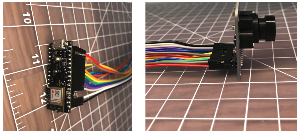
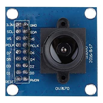
First, a quick review of the OV7670 camera module: According to its datasheet, it’s capable of capturing a VGA (640×480) color image at up to 30 FPS. The kit used for this project has the camera mounted to a small PCB and presents an 8-bit parallel data bus and various sync signals.
It requires an external “master clock” (MCLK in the photo) to drive its internal state machine which is used to generate all of the other timing signals. The Nano 33 can provide this external clock source by using its I2S clock. The OV767X library sets this master clock to 16Mhz (the camera can handle up to 48Mhz) and then there is a set of configuration registers to divide this value to arrive at the desired frame rate. Only a few possible frame rates are available (1, 5, 10, 15, 20, and 30 FPS).
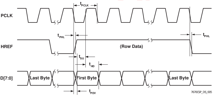
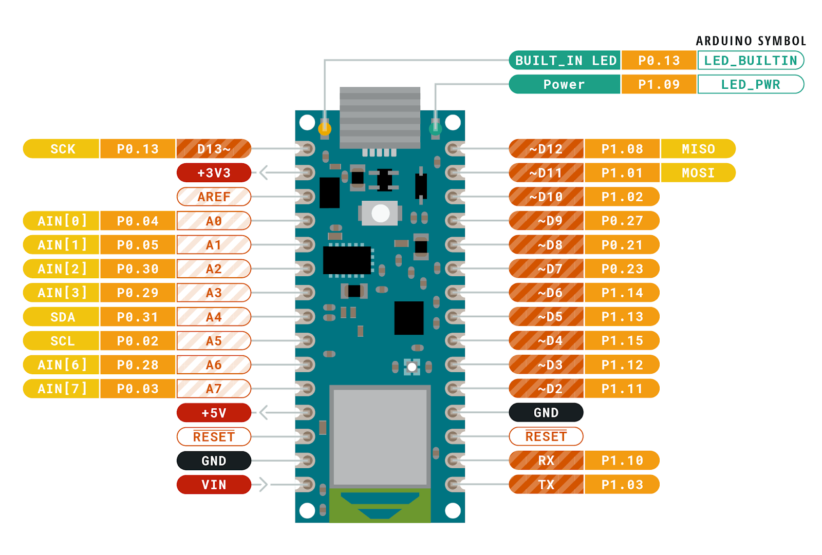
Above is one of the timing diagrams from the OV7670 datasheet. This particular drawing shows the timing of the data for each byte received along each image row. The HREF signal is used to signal the start and end of a row and then each byte is clocked in with the PCLK signal. The original library code read each bit (D0-D7) in a loop and combined them together to form each data byte. The image data comes quickly, so we have very little time to read each byte. Assembling them one bit at a time is not very efficient. You might be thinking that it’s not that hard of a problem to solve on the Nano 33. After all, it has 22 GPIO pins and the Cortex-M inside it has 32-bit wide GPIO ports, so just hook up the data bits sequentially and you’ll be able to read the 8 data bits in one shot, then Mission Accomplished™. If only things were that easy. The Nano 33 does have plenty of GPIO pins, but there isn’t a continuous sequence of 8 bits available using any of the pins! I’m guessing that the original code did it one bit at a time because it didn’t look like there was a better alternative. In the pinout diagram below, please notice the P0.xx and P1.xx numbers. These are the Cortex-M GPIO port 0 and 1-bit numbers (other Cortex-M processors would label them PA and PB).
I wasn’t going to let this little bump in the road stop me from making use of bit parallelism. If you look carefully at the bit positions, the best continuous run we can get is 6 bits in a row with P1.10 through P1.15. It’s not possible to read the 8 data bits in one shot…or is it? If we connect D0/D1 of the camera to P1.02/P1.03 and D2-D7 to P1.10-P1.15, we can do a single 32-bit read from port P1 and get all 8 bits in one shot. The bits are in order, but will have a gap between D1 and D2 (P1.04 to P1.09). Luckily the Arm CPU has what’s called a barrel shifter. It also has a smart instruction set which allows data to be shifted ‘for free’ at the same time the instruction is doing something else. Let’s take a look at how and why I changed the code:
Original:
uint8_t in = 0;
  for (int k = 0; k < 8; k++) {
     bitWrite(in, k, (*_dataPorts[k] & _dataMasks[k]) != 0);
  }
Optimized:
  uint32_t in = port->IN; // read all bits in parallel
  in >>= 2; // place bits 0 and 1 at the "bottom" of the
register
  in &= 0x3f03; // isolate the 8 bits we care about
  in |= (in >> 6); // combine the upper 6 and lower 2 bits
Code analysis
If you’re not interested in the nitty gritty details of the code changes I made, you can skip this section and go right to the results below.First, let’s look at what the original code did. When I first looked at it, I didn’t recognize bitWrite; apparently it’s not a well known Arduino bit manipulation macro; it’s defined as:
This macro was written with the intention of being used on GPIO ports (the variable value) where the logical state of bitvalue would be turned into a single write of a 0 or 1 to the appropriate bit. It makes less sense to be used on a regular variable because it inserts a branch to switch between the two possible outcomes. For the task at hand, it’s not necessary to use bitClear() on the in variable since it’s already initialized to 0 before the start of each byte loop. A better choice would be:
if (*_dataPorts[k] & _dataMasks[k]) in |= (1 << k);
The arrays _dataPorts[] and _dataMasks[] contain the memory mapped GPIO port addresses and bit masks to directly access the GPIO pins (bypassing digitalRead). So here’s a play-by-play of what the original code was doing:
Set in to 0
Set k to 0
Read the address of the GPIO port from _dataPorts[] at index k
Read the bit mask of the GPIO port from _dataMasks[] at index k
Read 32-bit data from the GPIO port address
Logical AND the data with the mask
Shift 1 left by k bits to prepare for bitClear and bitSet
Compare the result of the AND to zero
Branch to bitSet() code if true or use bitClear() if false
bitClear or bitSet depending on the result
Increment loop variable k
Compare k to the constant value 8
Branch if less back to step 3
Repeat steps 3 through 13, 8 times
Store the byte in the data array (not shown above)
The new code does the following:
Read the 32-bit data from the GPIO port address
Shift it right by 2 bits
Logical AND (mask) the 8 bits we’re interested in
Shift and OR the results to form 8 continuous bits
Store the byte in the data array (not shown above)
Each of the steps listed above basically translates into a single Arm instruction. If we assume that each instruction takes roughly the same amount of time to execute (mostly true on Cortex-M), then old vs. new is 91 versus 5 instructions to capture each byte of camera data, an 18x improvement! If we’re capturing a QVGA frame (320x240x2 = 153600 bytes), that becomes manymillionsof extra instructions.
Results
The optimized byte capture code translates into 5 Arm instructions and allows the capture loop to now handle a setting of 5 FPS instead of 1 FPS. The FPS numbers don’t seem to be exact, but the original capture time (QVGA @ 1 FPS) was 1.5 seconds while the new capture time when set to 5 FPS is 0.393 seconds. I tested 10 FPS, but readFrame() doesn’t read the data correctly at that speed. I don’t have an oscilloscope handy to probe the signals to see why it’s failing. The code may be fast enough now (I think it is), but the sync signals may become too unstable at that speed. I’ll leave this as an exercise to the readers who have the equipment to see what happens to the signals at 10 FPS.
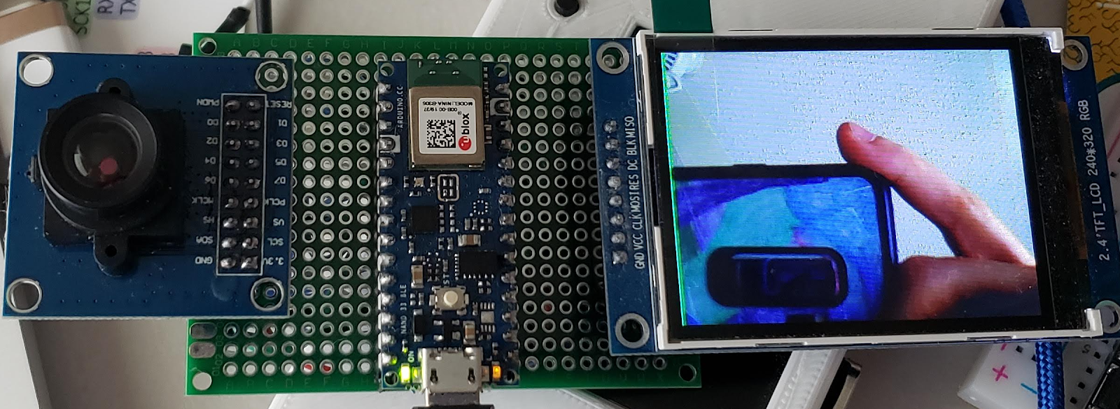
For the work I did on the OV767X library, I created a test fixture to make sure that the camera data was being received correctly. For ML/data processing applications, it’s not necessary to do this. The built-in camera test pattern can be used to confirm the integrity of the data by using a CRC32.
My tinned protoboard test fixture with 320×240 LCD
Note: The frames come one immediately after another. If you capture a frame and then do some processing and then try to capture another frame, you may hit the middle of the next frame when you call readFrame(). The code will then wait until the next VSync signal, so that frame’s capture time could be as much as 2x as long as a single frame time.
More tips
I enjoy testing the limits of embedded hardware, especially when it involves bits, bytes and pixels. I’ve written a few blog posts that explore the topics of speed and power usage if you’re interested in learning more about it.
Conclusion
The embedded microcontrollers available today are capable of handling jobs that were unimaginable just a few years ago.
Optimized ML solutions from Google and Edge Impulse are capable of running on low-cost, battery-powered boards (vision, vibration, audio, whatever sensor you want to monitor).
Python and Arduino programming environments can test your project idea with little effort.
Software can be written an infinite number of ways to accomplish the same task, but one constant remains: TANSTATFC (there ain’t no such thing as the fastest code).
Never assume the performance you’re seeing is what you’re stuck with. Think of existing libraries and generic APIs available through open source libraries and environments as a starting point.
Knowing a bit of info about the target platform can be helpful, but it’s not necessary to read the MCU datasheet. In the code above, the larger concept of Arm Cortex-M 32-bit GPIO ports was sufficient to accomplish the task without knowing the specifics of the nRF52’s I/O hardware.
Don’t be afraid to dig a little deeper and test every assumption.
If you encounter difficulties, the community is large and there are a ton of resources out there. Asking for help is a sign of strength, not weakness.
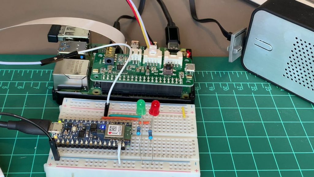
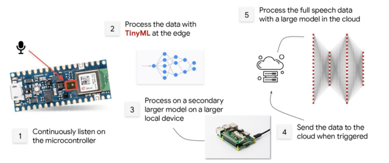
Smart speakers are amazing devices, able to answer a near-infinite array of questions, as well as offer a variety of AI services. As shown in this project write-up by Marcelo Rovai, you can emulate a Google Assistant with Raspberry Pi and ReSpeaker 2-Mics Pi HAT, which can be triggered to “wake” and respond to your voice queries with a physical button.
To take this system to the next level, he’s leveraging an Arduino Nano 33 BLE Sense that replaces the button with a virtual one through keyword spotting. The tinyML-enabled Nano then listens for “yes” using its onboard microphone. When activated, it sends a signal to the Raspberry Pi, which in turn processes subsequent requests via the Google Cloud.
This aerial system launches Nano 33 BLE Sense darts for data collection
Arduino Team — October 29th, 2020
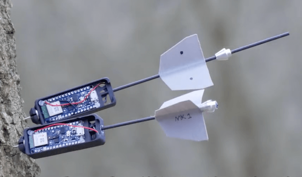
Sensor deployment via unmanned aerial vehicles is an interesting concept. Up until now, you’ve had two options: use a drone that drops sensors onto the ground, or one with some kind of manipulator to stick them in particular place. However, researchers at Imperial College London have been studying a third approach, which shoots sensor pods from an aerial platform like darts.
The system utilizes a compressed spring, along with a shape-memory alloy (SMA) trigger to fling the sensor pods at a nearby surface, at up to a four-meter range. The actual sensor package used here is an Arduino Nano 33 BLE Sense, allowing for a variety of measurements without extra hardware in hazardous environments or inaccessible locations.
Several methods of attachment were proposed, including magnets and chemical bonding, but the experiment’s research paper focuses on dart-like wood attachment, since this would require the most force.
More details on the project can be found on IEEE Spectrum and in the video below.
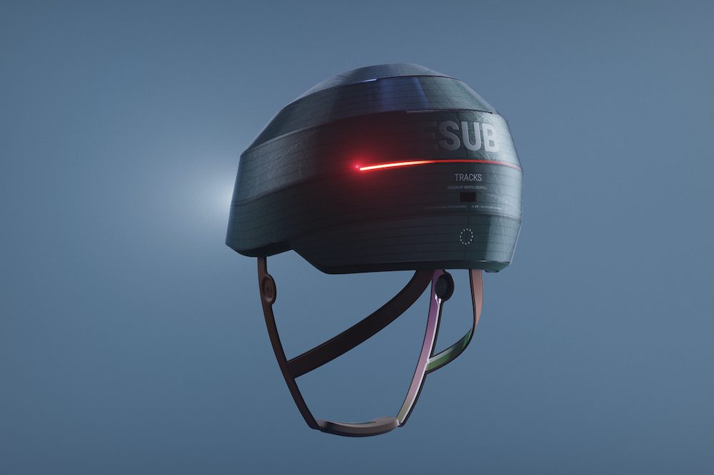
ESUB Tracks is a smart bicycle helmet with built-in electronics for enhanced safety
Arduino Team — October 27th, 2020
Bike helmets can help minimize injuries in the event of an accident, but could a helmet also be used to help prevent a crash, or even enhance your riding experience? ESUB Tracks from WertelOberfell attempts to do both, featuring a variety of electronic enhancements which are powered by photovoltaic cells wrapped around its outer surface.
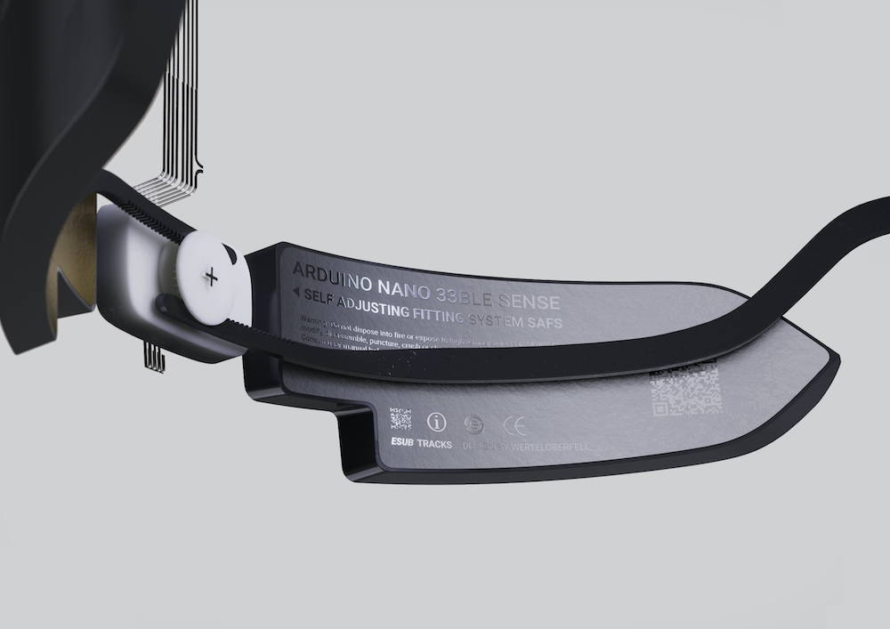
ESUB Tracks includes a lighting arrangement on the back for turn signaling, triggered using voice commands to the helmet’s piezoelectric microphone. Additionally, it has a sensor to detect rapidly approaching vehicles from behind, warning the wearer of this condition via haptic feedback. Bone-conductive speakers are provided for listening to Bluetooth audio, and if all of that wasn’t enough, it even tightens down the straps when the buckle is fastened.
Overall control is accomplished using an Arduino Nano 33 BLE Sense, and you can see more of this amazing device in the video below.
Upgrading an inexpensive exercise bike with a Nano 33 BLE Sense
Arduino Team — October 8th, 2020
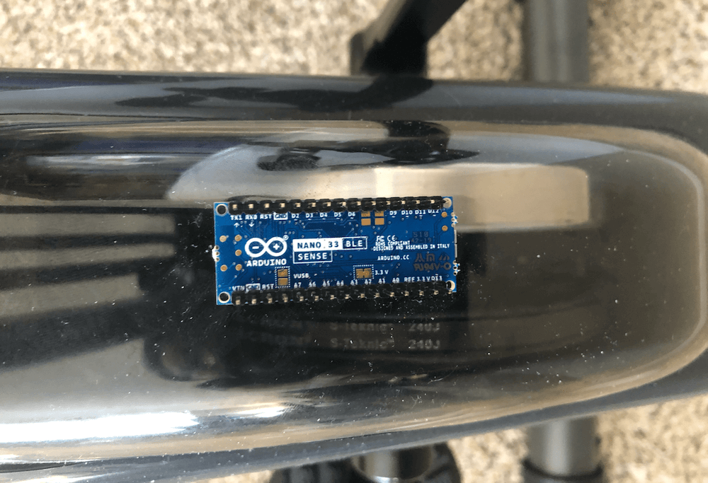
After purchasing a basic foldable exercise bike, Thomas Schucker wondered if he could get a bit more out of it, perhaps even using it with virtual riding apps like Zwift and RGT. By default, this piece of equipment is set up to output cadence info via a simple headphone jack, using a demagnetized portion of the flywheel for sensing.
Taking this a step further, Schucker found that the magnetic field amplitude actually changes with the resistance input, allowing him to correlate the two with an analog sensor built into the Arduino Nano 33 BLE Sense.
The Nano is attached near the flywheel, and sends data over BLE, enabling him to use this rather cheap indoor bike in a much more involved way than it was likely ever intended. Code for the project is available on GitHub, while a demo of it controlling Zwift can be seen in the video below.
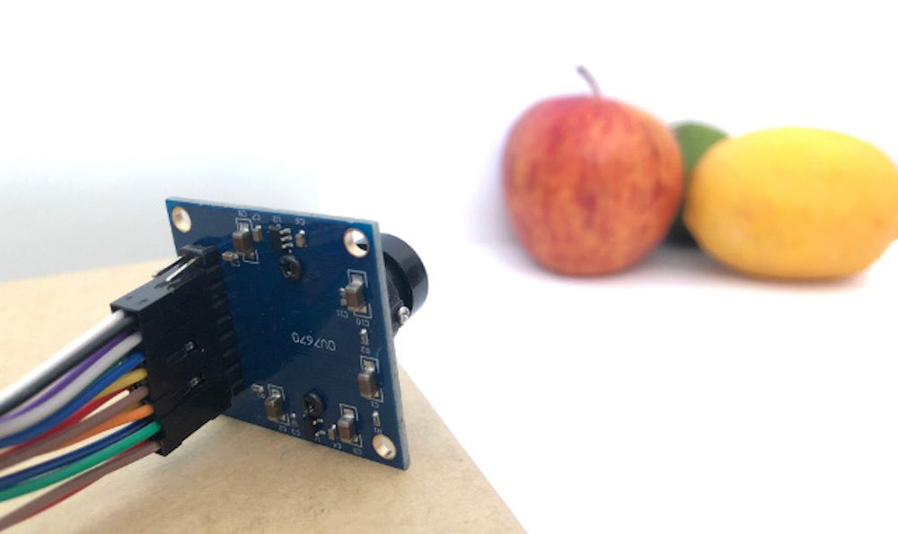
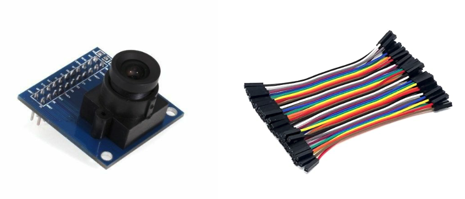
If you’re interested in embedded machine learning (TinyML) on the Arduino Nano 33 BLE Sense, you’ll have found a ton of on-board sensors — digital microphone, accelerometer, gyro, magnetometer, light, proximity, temperature, humidity and color — but realized that for vision you need to attach an external camera.
In this article, we will show you how to get image data from a low-cost VGA camera module. We’ll be using the Arduino_OVD767x library to make the software side of things simpler.
Hardware setup
To get started, you will need:
You can of course get a board without headers and solder instead, if that’s your preference.
The one downside to this setup is that (in module form) there are a lot of jumpers to connect. It’s not hard but you need to take care to connect the right cables at either end. You can use tape to secure the wires once things are done, lest one comes loose.
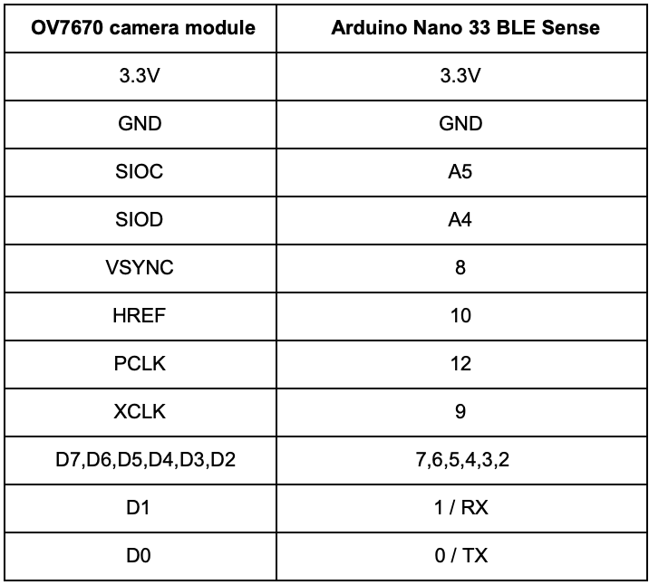
You need to connect the wires as follows:
Software setup
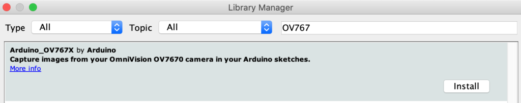
First, install the Arduino IDE or register for Arduino Create tools. Once you install and open your environment, the camera library is available in the library manager.
Tools > Manage Libraries and search for the OV767 library
Press the Install button
Now, we will use the example sketch to test the cables are connected correctly:
Examples > Arduino_OV767X > CameraCaptureRawBytes
Uncomment (remove the //) from line 48 to display a test pattern
Camera.testPattern();
Compile and upload to your board
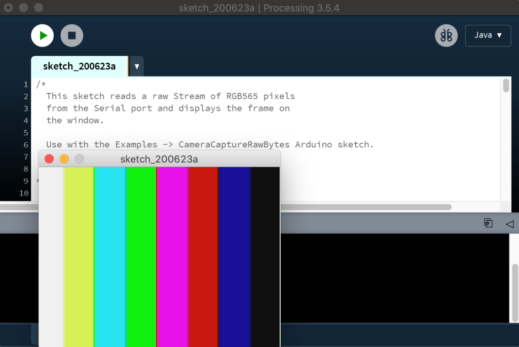
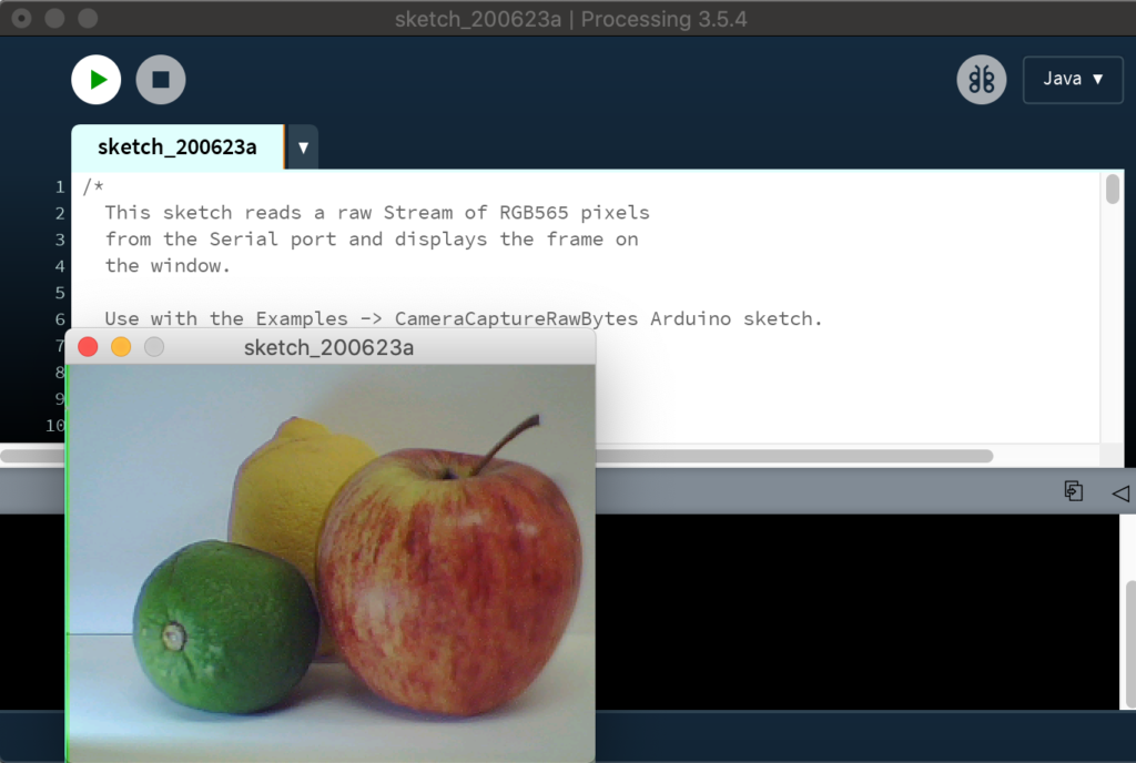
Your Arduino is now outputting raw image binary over serial. To view this as an image we’ve included a special application to view the image output from the camera using Processing.
Processing is a simple programming environment that was created by graduate students at MIT Media Lab to make it easier to develop visually oriented applications with an emphasis on animation and providing users with instant feedback through interaction.
Edit line 31-37 to match the machine and serial port your Arduino is connected to
Hit the play button in Processing and you should see a test pattern (image update takes a couple of seconds):
If all goes well, you should see the striped test pattern above!
Next we will go back to the Arduino IDE and edit the sketch so the Arduino sends a live image from the camera in the Processing viewer:
Return to the Arduino IDE
Comment out line 48 of the Arduino sketch
// We've disabled the test pattern and will display a live image
// Camera.testPattern();
Compile and upload to the board
Once the sketch is uploaded hit the play button in Processing again
After a few seconds you should now have a live image:
Considerations for TinyML
The full VGA (640×480 resolution) output from our little camera is way too big for current TinyML applications. uTensor runs handwriting detection with MNIST that uses 28×28 images. The person detection example in the TensorFlow Lite for Microcontrollers example uses 96×96 which is more than enough. Even state-of-the-art ‘Big ML’ applications often only use 320×320 images (see the TinyML book). Also consider an 8-bit grayscale VGA image occupies 300KB uncompressed and the Nano 33 BLE Sense has 256KB of RAM. We have to do something to reduce the image size!
Camera format options
The OV7670 module supports lower resolutions through configuration options. The options modify the image data before it reaches the Arduino. The configurations currently available via the library today are:
VGA – 640 x 480
CIF – 352 x 240
QVGA – 320 x 240
QCIF – 176 x 144
This is a good start as it reduces the amount of time it takes to send an image from the camera to the Arduino. It reduces the size of the image data array required in your Arduino sketch as well. You select the resolution by changing the value in Camera.begin. Don’t forget to change the size of your array too.
Camera.begin(QVGA, RGB565, 1)
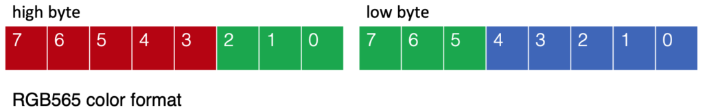
The camera library also offers different color formats: YUV422, RGB444 and RGB565. These define how the color values are encoded and all occupy 2 bytes per pixel in our image data. We’re using the RGB565 format which has 5 bits for red, 6 bits for green, and 5 bits for blue:
Converting the 2-byte RGB565 pixel to individual red, green, and blue values in your sketch can be accomplished as follows:
// Convert from RGB565 to 24-bit RGB uint16_t pixel = (high << 8) | low; int red = ((pixel >> 11) & 0x1f) << 3; int green = ((pixel >> 5) & 0x3f) << 2; int blue = ((pixel >> 0) & 0x1f) << 3;
Resizing the image on the Arduino
Once we get our image data onto the Arduino, we can then reduce the size of the image further. Just removing pixels will give us a jagged (aliased) image. To do this more smoothly, we need a downsampling algorithm that can interpolate pixel values and use them to create a smaller image.
The techniques used to resample images is an interesting topic in itself. We found this downsampling example from Eloquent Arduino works with fine the Arduino_OV767X camera library output (see animated GIF above).
Applications like the TensorFlow Lite Micro Person Detection example that use CNN based models on Arduino for machine vision may not need any further preprocessing of the image — other than averaging the RGB values in order to remove color for 8-bit grayscale data per pixel.
However, if you do want to perform normalization, iterating across pixels using the Arduino max and min functions is a convenient way to obtain the upper and lower bounds of input pixel values. You can then use map to scale the output pixel values to a 0-255 range.
This was an introduction to how to connect an OV7670 camera module to the Arduino Nano 33 BLE Sense and some considerations for obtaining data from the camera for TinyML applications. There’s a lot more to explore on the topic of machine vision on Arduino — this is just a start!
Bike signal display keeps riders safe with machine learning
Arduino Team — June 21st, 2020
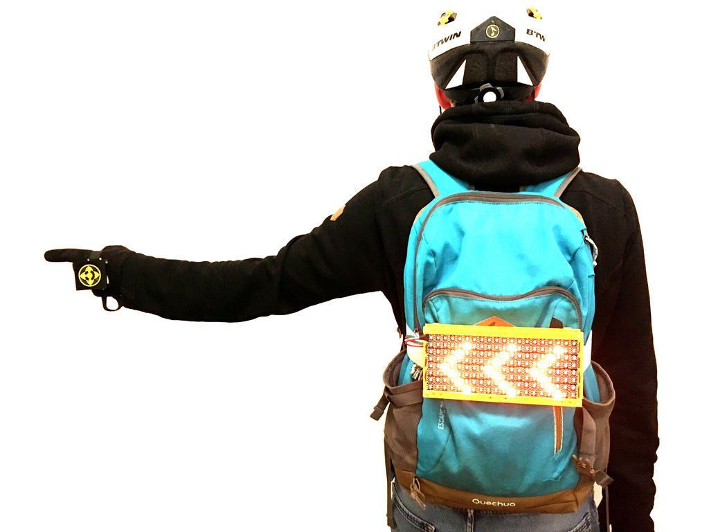
Cycling can be fun, not to mention great exercise, but is also dangerous at times. In order to facilitate safety and harmony between road users on his hour-plus bike commute in Marseille, France, Maltek created his own LED backpack signaling setup.
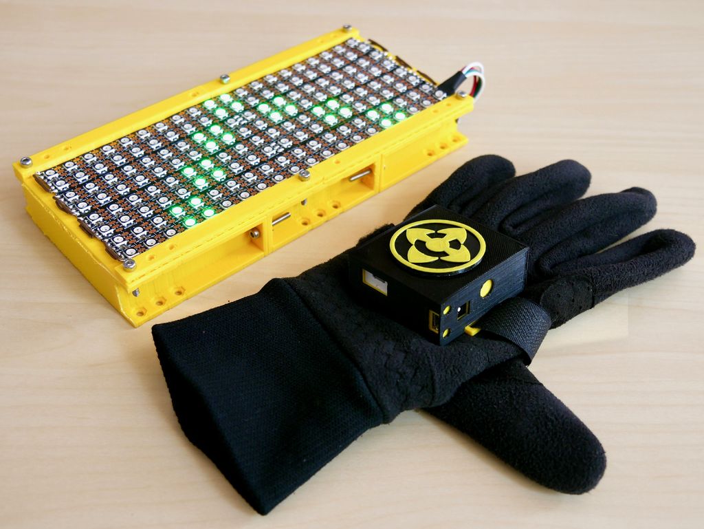
The device uses a hand mounted Arduino Nano 33 BLE Sense to record movement via its onboard IMU and runs a TinyML gesture recognition model to translate this into actual road signals. Left and right rotations of the wrist are passed along to the backpack unit over BLE, which shows the corresponding turn signal on its LED panel.
Other gestures include a back twist for stop, forward twist to say “merci,” and it displays a default green forward scrolling arrow as the default state.
Machine learning (ML) algorithms come in all shapes and sizes, each with their own trade-offs. We continue our exploration of TinyML on Arduino with a look at the Arduino KNN library.
In addition to powerful deep learning frameworks like TensorFlow for Arduino, there are also classical ML approaches suitable for smaller data sets on embedded devices that are useful and easy to understand — one of the simplest is KNN.
One advantage of KNN is once the Arduino has some example data it is instantly ready to classify! We’ve released a new Arduino library so you can include KNN in your sketches quickly and easily, with no off-device training or additional tools required.
In this article, we’ll take a look at KNN using the color classifier example. We’ve shown the same application with deep learning before — KNN is a faster and lighter weight approach by comparison, but won’t scale as well to larger more complex datasets.
Color classification example sketch
In this tutorial, we’ll run through how to classify objects by color using the Arduino_KNN library on the Arduino Nano 33 BLE Sense.
Select ColorClassifier from File > Examples > Arduino_KNN
Compile this sketch and upload to your Arduino board
The Arduino_KNN library
The example sketch makes use of the Arduino_KNN library. The library provides a simple interface to make use of KNN in your own sketches:
#include <Arduino_KNN.h> // Create a new KNNClassifier
KNNClassifier myKNN(INPUTS);
In our example INPUTS=3 – for the red, green and blue values from the color sensor.
Sampling object colors
When you open the Serial Monitor you should see the following message:
Arduino KNN color classifier
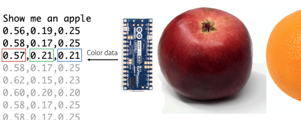
Show me an example Apple
The Arduino board is ready to sample an object color. If you don’t have an Apple, Pear and Orange to hand you might want to edit the sketch to put different labels in. Keep in mind that the color sensor works best in a well lit room on matte, non-shiny objects and each class needs to have distinct colors! (The color sensor isn’t ideal to distinguish between an orange and a tangerine — but it could detect how ripe an orange is. If you want to classify objects by shape you can always use a camera.)
When you put the Arduino board close to the object it samples the color and adds it to the KNN examples along with a number labelling the class the object belongs to (i.e. numbers 0,1 or 2 representing Apple, Orange or Pear). ML techniques where you provide labelled example data are also called supervised learning.
The code in the sketch to add the example data to the KNN function is as follows:
readColor(color); // Add example color to the KNN model
myKNN.addExample(color, currentClass);
The red, green and blue levels of the color sample are also output over serial:
The sketch takes 30 color samples for each object class. You can show it one object and it will sample the color 30 times — you don’t need 30 apples for this tutorial! (Although a broader dataset would make the model more generalized.)
Classification
With the example samples acquired the sketch will now ask to guess your object! The example reads the color sensor using the same function as it uses when it acquired training data — only this time it calls the classify function which will guess an object class when you show it a color:
readColor(color); // Classify the object classification = myKNN.classify(color, K);
You can try showing it an object and see how it does:
Let me guess your object
0.44,0.28,0.28
You showed me an Apple
Note: It will not be 100% accurate especially if the surface of the object varies or the lighting conditions change. You can experiment with different numbers of examples, values for k and different objects and environments to see how this affects results.
How does KNN work?
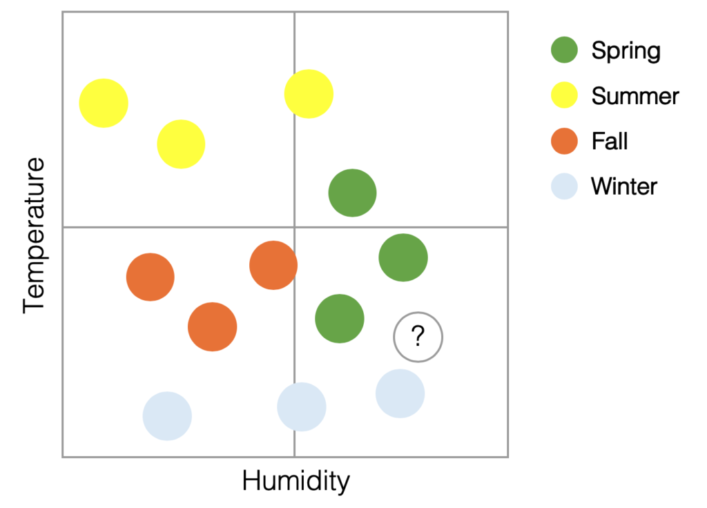
Although the Arduino_KNN library does the math for you it’s useful to understand how ML algorithms work when choosing one for your application. In a nutshell, the KNN algorithm classifies objects by comparing how close they are to previously seen examples. Here’s an example chart with average daily temperature and humidity data points. Each example is labelled with a season:
To classify a new object (the “?” on the chart) the KNN classifier looks for the most similar previous example(s) it has seen. As there are two inputs in our example the algorithm does this by calculating the distance between the new object and each of the previous examples. You can see the closest example above is labelled “Winter”.
The k in KNN is just the number of closest examples the algorithm considers. With k=3 it counts the three closest examples. In the chart above the algorithm would give two votes for Spring and one for Winter — so the result would change to Spring.
One disadvantage of KNN is the larger the amount of training example data there is, the longer the KNN algorithm needs to spend checking each time it classifies an object. This makes KNN less feasible for large datasets and is a major difference between KNN and a deep learning based approach.
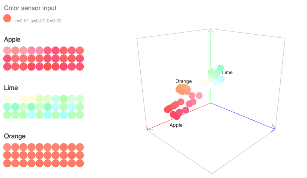
Classifying objects by color
In our color classifier example there are three inputs from the color sensor. The example colors from each object can be thought of as points in three dimensional space positioned on red, green and blue axes. As usual the KNN algorithm guesses objects by checking how close the inputs are to previously seen examples, but because there are three inputs this time it has to calculate the distances in three dimensional space. The more dimensions the data has the more work it is to compute the classification result.
Further thoughts
This is just a quick taste of what’s possible with KNN. You’ll find an example for board orientation in the library examples, as well as a simple example for you to build on. You can use any sensor on the BLE Sense board as an input, and even combine KNN with other ML techniques.
Of course there are other machine learning resources available for Arduino include TensorFlow Lite tutorials as well as support from professional tools such as Edge Impulse and Qeexo. We’ll be inviting more experts to explore machine learning on Arduino more in the coming weeks.
The COVID-19 pandemic has changed the way we interact with people, things, and the world around us. We’re calling on the community to use an Arduino Nano or MKR board to build solutions that can help us practice better social distancing, improve queue management, or enable touch-free technologies.
Stepping out from our homes, to go to schools, factories, offices and pursue leisure pastimes all these will need to change as lockdown restrictions are eased. With terms like social distancing, remote learning and remote working becoming the norm, let’s see how your ideas can help the world move forward and rebuild everyday life based on a project in one of these two categories.
Category 1: Touch-Free
Create a solution that can be applied to devices that currently rely upon manually pushing a button e.g. elevators, pedestrian crossings, door entry systems, sanitizer dispensers, etc.
Category 2: Social Distance Enablement and Tracking
Create a solution that will allow individuals to maintain the recommended distance apart (1m to 2m) to safely work in the office, factory, commute to work on public transport, or socially interact in cafes and parks. The time people spend within close proximity to each other may also be a factor considered within the design.
N.B. The purpose of the competition is to create products and solutions that are ready to help people around the world to move forward with their lives and safely emerge from lockdown restrictions, rather than developing medical devices.
Contest Scope and Schedule
As any potential solution may be required to operate in a variety of environments, important factors to consider as part of the design process are reliability, durability, connectivity, and power management — hence the option to base your project on any Arduino Nano or MKR board.
The Arduino MKR Family represents the ideal solution for emerging battery powered IoT edge applications. All of the MKR boards share a common pinout for developers to easily shift between wireless communication protocols with minimal software changes, and in a cost efficient manner.
The Arduino Nano Family offers a tiny format, powerful processors and excellent reliability. All of the Nano boards can run embedded machine learning (AI).
Phase 2: Submit your project — Deadline July 14th, 2020: Submit your project for a chance to win up to $10,000 worth of prizes!
Prizes
We are giving away tens of thousands of dollars in prizes to the top five projects, including product assessment and marketing support to bring your project to market! Our judges are going to pick the best qualifying projects based on the judging criteria outlined in the rules section.
Grand Prize
$5,000 voucher for hardware on the Newark online store $750 of pre-manufacturing assessment with Dragon Innovation $5,000 towards product marketing with Hackster.io
Touch-Free
1st Place — Touch-Free
$1,500 voucher for hardware on the Newark online store $750 of pre-manufacturing assessment with Dragon Innovation $3,000 towards product marketing with Hackster.io
2nd Place — Touch-Free
$500 voucher for hardware on the Newark online store $750 of pre-manufacturing assessment with Dragon Innovation $2,000 towards product marketing with Hackster.io
Social Distance Enablement & Tracking
1st Place — Social Distance Enablement & Tracking
$1,500 voucher for hardware on the Newark online store $750 of pre-manufacturing assessment with Dragon Innovation $3,000 towards product marketing with Hackster.io
2nd Place — Social Distance Enablement & Tracking
$500 voucher for hardware on the Newark online store $750 of pre-manufacturing assessment with Dragon Innovation $2,000 towards product marketing with Hackster.io
This post is written by Jan Jongboom and Dominic Pajak.
Running machine learning (ML) on microcontrollers is one of the most exciting developments of the past years, allowing small battery-powered devices to detect complex motions, recognize sounds, or find anomalies in sensor data. To make building and deploying these models accessible to every embedded developer we’re launching first-class support for the Arduino Nano 33 BLE Sense and other 32-bit Arduino boards in Edge Impulse.
The trend to run ML on microcontrollers is called Embedded ML or Tiny ML. It means devices can make smart decisions without needing to send data to the cloud – great from an efficiency and privacy perspective. Even powerful deep learning models (based on artificial neural networks) are now reaching microcontrollers. This past year great strides were made in making deep learning models smaller, faster and runnable on embedded hardware through projects like TensorFlow Lite Micro, uTensor and Arm’s CMSIS-NN; but building a quality dataset, extracting the right features, training and deploying these models is still complicated.
Using Edge Impulse you can now quickly collect real-world sensor data, train ML models on this data in the cloud, and then deploy the model back to your Arduino device. From there you can integrate the model into your Arduino sketches with a single function call. Your sensors are then a whole lot smarter, being able to make sense of complex events in the real world. The built-in examples allow you to collect data from the accelerometer and the microphone, but it’s easy to integrate other sensors with a few lines of code.
Download the Arduino Nano 33 BLE Sense firmware — this is a special firmware package (source code) that contains all code to quickly gather data from its sensors. Launch the flash script for your platform to flash the firmware.
Launch the Edge Impulse daemon to connect your board to Edge Impulse. Open a terminal or command prompt and run:
Your device now shows in the Edge Impulse studio on the Devices tab, ready for you to collect some data and build a model.
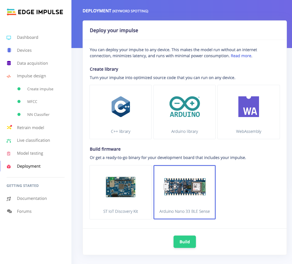
Once you’re done you can deploy your model back to the Arduino Nano 33 BLE Sense. Either as a binary which includes your full ML model, or as an Arduino library which you can integrate in any sketch.
Deploying to Arduino from Edge Impulse
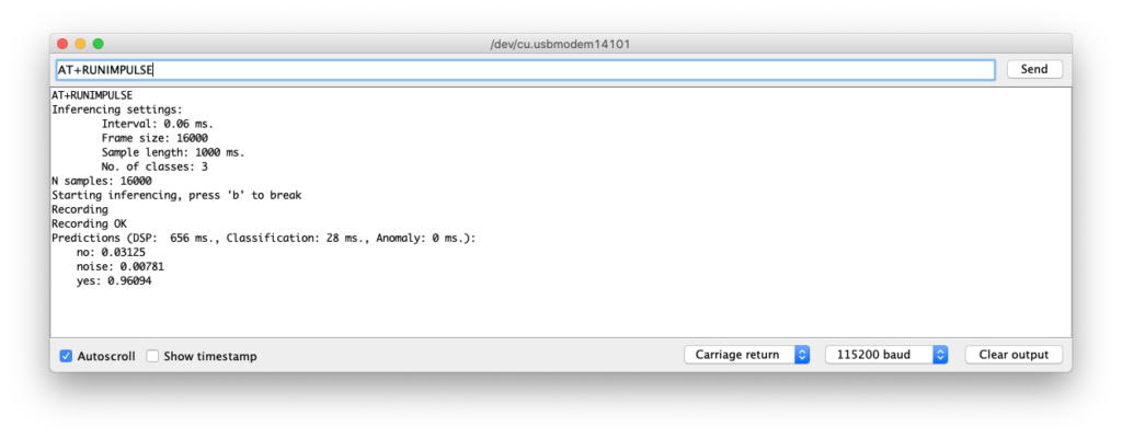
Your machine learning model is now running on the Arduino board. Open the serial monitor and run `AT+RUNIMPULSE` to start classifying real world data!
Keyword spotting on the Arduino Nano 33 BLE Sense
Integrates with your favorite Arduino platform
We’ve launched with the Arduino Nano 33 BLE Sense, but you can also integrate Edge Impulse with your favourite Arduino platform. You can easily collect data from any sensor and development board using the Data forwarder. This is a small application that reads data over serial and sends it to Edge Impulse. All you need is a few lines of code in your sketch (here’s an example).
After you’ve built a model you can easily export your model as an Arduino library. This library will run on any Arm-based Arduino platform including the Arduino MKR family or Arduino Nano 33 IoT, providing it has enough RAM to run your model. You can now include your ML model in any Arduino sketch with just a few lines of code. After you’ve added the library to the Arduino IDE you can find an example on integrating the model under Files > Examples > Your project – Edge Impulse > static_buffer.
To run your models as fast and energy-efficiently as possible we automatically leverage the hardware capabilities of your Arduino board – for example the signal processing extensions available on the Arm Cortex-M4 based Arduino Nano BLE Sense or more powerful Arm Cortex-M7 based Arduino Portenta H7. We also leverage the optimized neural network kernels that Arm provides in CMSIS-NN.
A path to production
This release is the first step in a really exciting collaboration. We believe that many embedded applications can benefit from ML today, whether it’s for predictive maintenance (‘this machine is starting to behave abnormally’), to help with worker safety (‘fall detected’), or in health care (‘detected early signs of a potential infection’). Using Edge Impulse with the Arduino MKR family you can already quickly deploy simple ML based applications combined with LoRa, NB-IoT cellular, or WiFi connectivity. Over the next months we’ll also add integrations for the Arduino Portenta H7 on Edge Impulse, making higher performance industrial applications possible.
On a related note: if you have ideas on how TinyML can help to slow down or detect the COVID-19 virus, then join the UNDP COVID-19 Detect and Protect Challenge. For inspiration, see Kartik Thakore’s blog post on cough detection with the Arduino Nano 33 BLE Sense and Edge Impulse.
We can’t wait to see what you’ll build!
Jan Jongboom is the CTO and co-founder of Edge Impulse. He built his first IoT projects using the Arduino Starter Kit.
Dominic Pajak is VP Business Development at Arduino.
Designing a two-axis gesture-controlled platform for DSLR cameras
Arduino Team — January 3rd, 2020
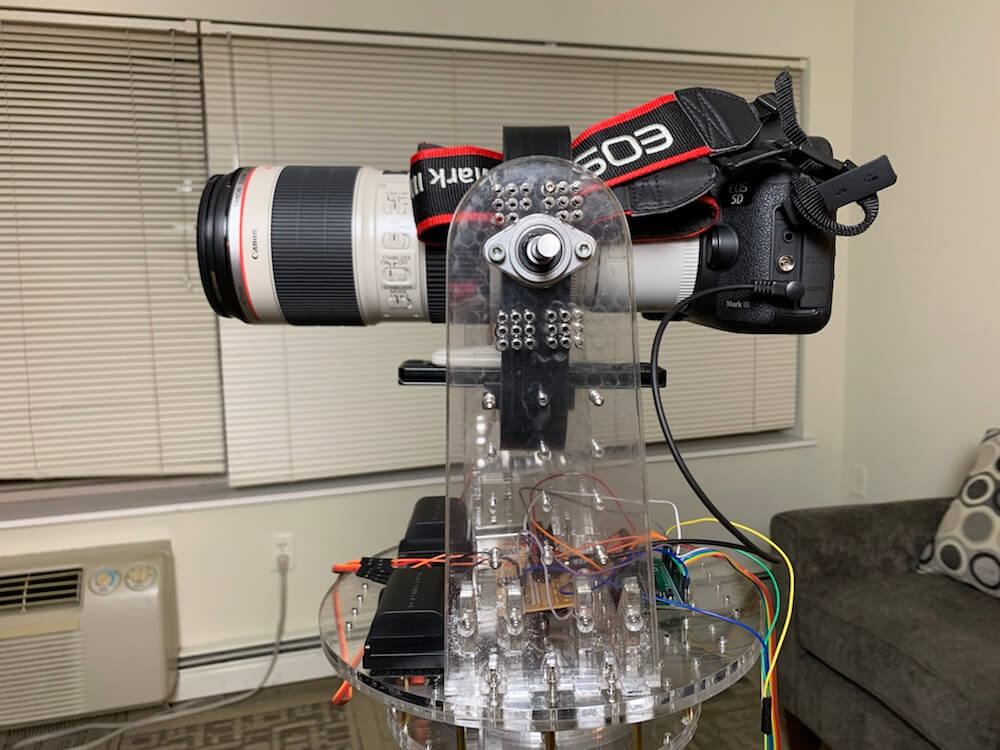
Holding your phone up to take an occasional picture is no big deal, but for professional photographers who often need to manipulate heavier gear for hours on end, this can actually be quite tiring. With this in mind, Cornell University students Kunpeng Huang, Xinyi Yang, and Siqi Qian designed a two-axis gesture-controlled camera platform for their ECE 4760 final project.
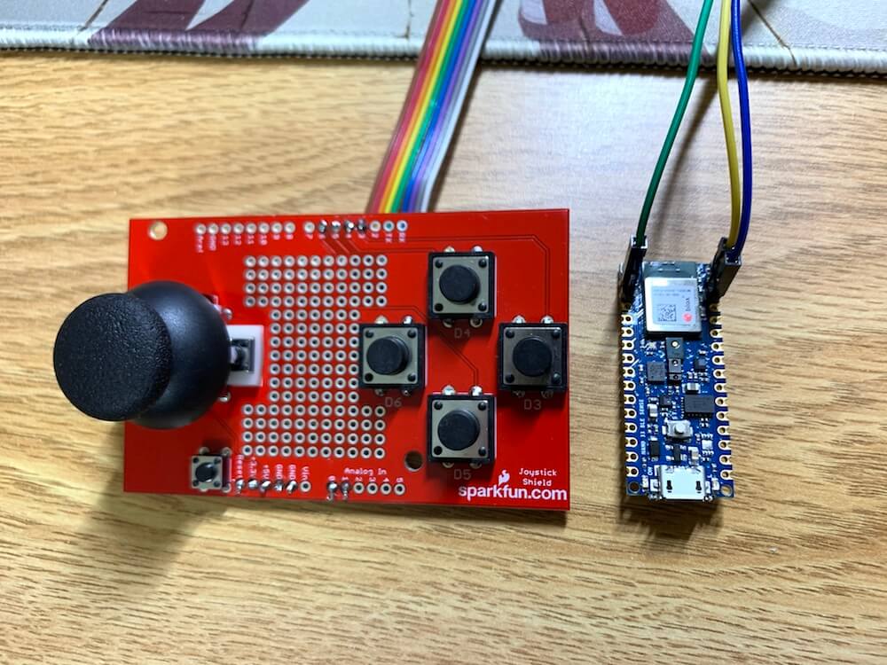
Their device mounts a 3.6kg (~8lb) DSLR camera in an acrylic turret, allowing it to look up and down (pitch) as well as left and right (yaw) under the control of two servo motors. The platform is powered by a PIC32 microcontroller, while human operation is performed via a gamepad-style SparkFun Joystick Shield or through an Arduino Nano 33 BLE Sense.
When in Nano mode, the setup leverages its IMU to move the camera along with the user’s hand gestures, and its built-in light and proximity sensing abilities activate the camera itself.
Our 2-DOF gesture-controlled platform can point the camera in any direction within a hemi-sphere based on spherical coordinates. It is capable of rotating continuously in horizontal direction and traversing close to 180 degrees in vertical direction. It is able to support a relatively large camera system (more than 3kg in total weight and 40cm in length), orient the camera accurately (error less than 3 degree), and respond quickly to user input (transverse 180 degrees in less than 3 seconds). In addition to orienting the camera, the system also has simple control functionality, such as allowing the user to auto-focus and take photos remotely, which is achieved through DSLR’s peripheral connections.
At a high level, our design supports three user input modes — the first one uses a joystick while the other two use an inertial measurement unit (IMU). In the first mode, the x- and y-axis of a joystick is mapped to the velocities in the yaw and pitch directions of the camera. In the second mode, the roll and pitch angles of the user’s hand are mapped to the velocities of the camera in the yaw and pitch directions, while the third mode mapped the angles to the angular position of the camera.
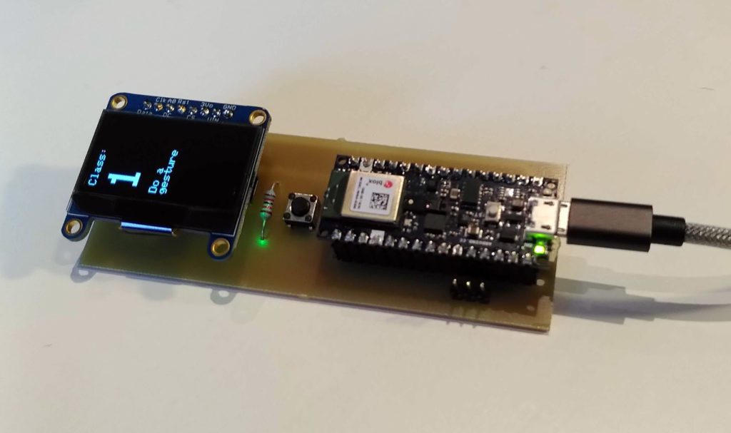
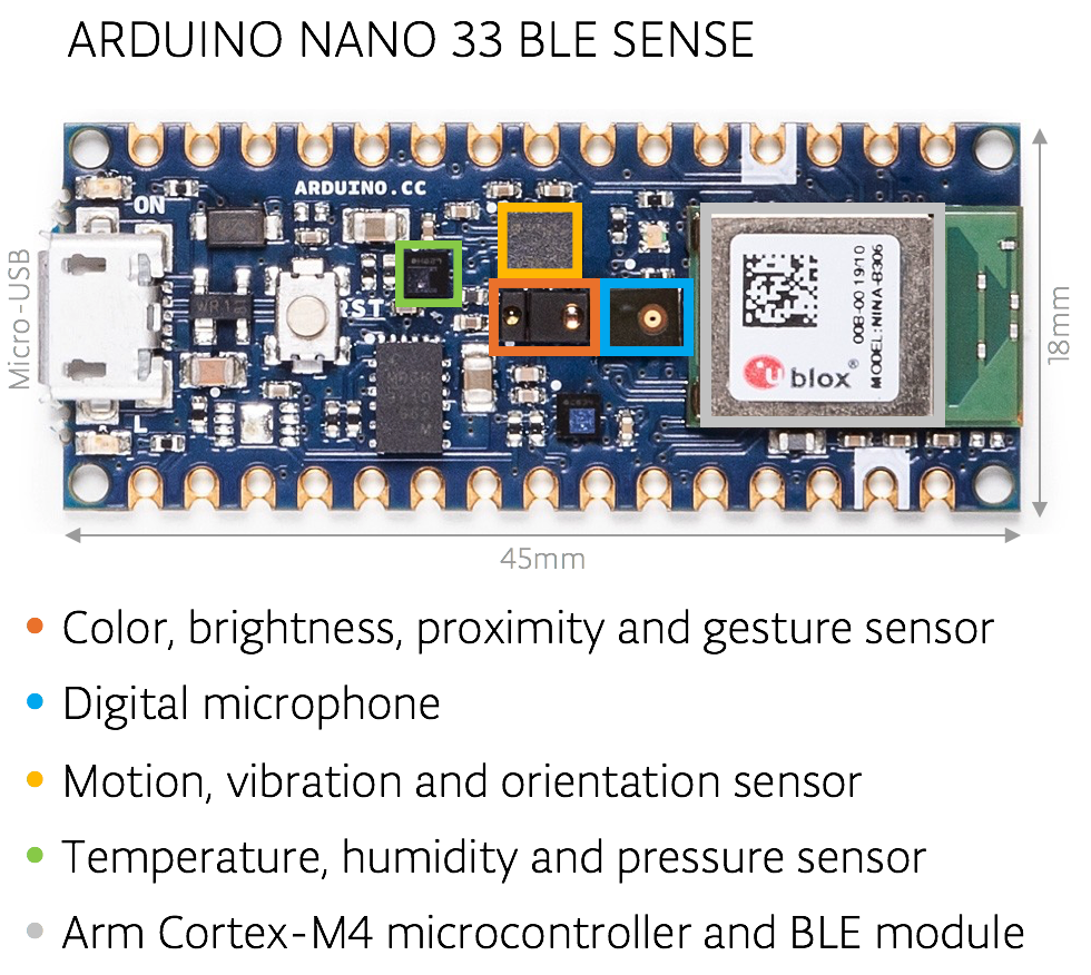
Arduino is on a mission to make machine learning easy enough for anyone to use. The other week we announced the availability of TensorFlow Lite Micro in the Arduino Library Manager. With this, some cool ready-made ML examples such as speech recognition, simple machine vision and even an end-to-end gesture recognition training tutorial. For a comprehensive background we recommend you take a look at that article.
In this article we are going to walk through an even simpler end-to-end tutorial using the TensorFlow Lite Micro library and the Arduino Nano 33 BLE Sense’s colorimeter and proximity sensor to classify objects. To do this, we will be running a small neural network on the board itself.
Arduino BLE 33 Nano Sense running TensorFlow Lite Micro
The philosophy of TinyML is doing more on the device with less resources – in smaller form-factors, less energy and lower cost silicon. Running inferencing on the same board as the sensors has benefits in terms of privacy and battery life and means its can be done independent of a network connection.
The fact that we have the proximity sensor on the board means we get an instant depth reading of an object in front of the board – instead of using a camera and having to determine if an object is of interest through machine vision.
In this tutorial when the object is close enough we sample the color – the onboard RGB sensor can be viewed as a 1 pixel color camera. While this method has limitations it provides us a quick way of classifying objects only using a small amount of resources. Note that you could indeed run a complete CNN-based vision model on-device. As this particular Arduino board includes an onboard colorimeter, we thought it’d be fun and instructive to demonstrate in this way to start with.
We’ll show a simple but complete end-to-end TinyML application can be achieved quickly and without a deep background in ML or embedded. What we cover here is data capture, training, and classifier deployment. This is intended to be a demo, but there is scope to improve and build on this should you decide to connect an external camera down the road. We want you to get an idea of what is possible and a starting point with tools available.
The Arduino Nano 33 BLE Sense board we’re using here has an Arm Cortex-M4 microcontroller running mbedOS and a ton of onboard sensors – digital microphone, accelerometer, gyroscope, temperature, humidity, pressure, light, color and proximity.
While tiny by cloud or mobile standards the microcontroller is powerful enough to run TensorFlow Lite Micro models and classify sensor data from the onboard sensors.
Setting up the Arduino Create Web Editor
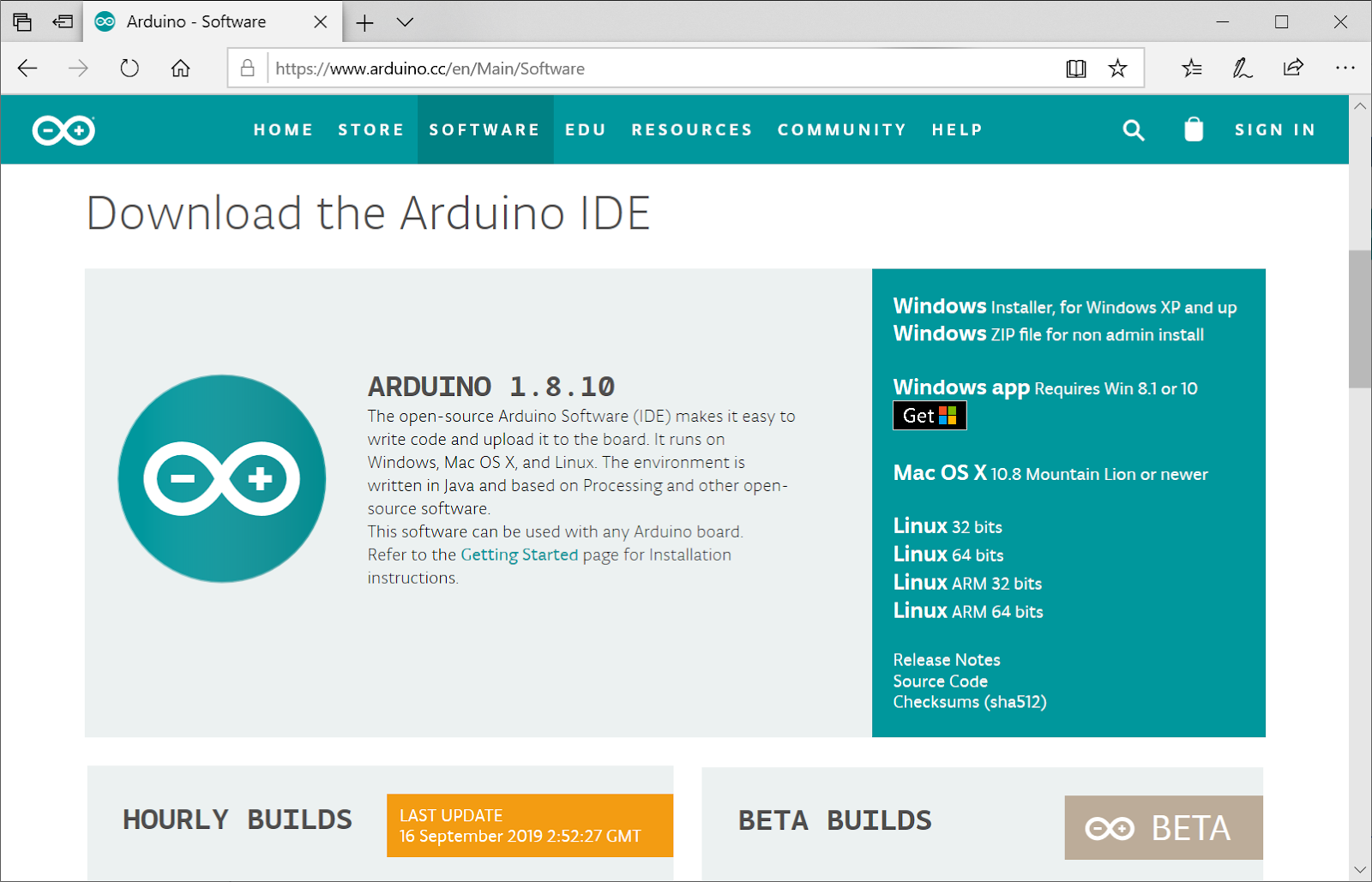
In this tutorial we’ll be using the Arduino Create Web Editor – a cloud-based tool for programming Arduino boards. To use it you have to sign up for a free account, and install a plugin to allow the browser to communicate with your Arduino board over USB cable.
You can get set up quickly by following the getting started instructions which will guide you through the following:
Download and install the plugin
Sign in or sign up for a free account
(NOTE: If you prefer, you can also use the Arduino IDE desktop application. The setup for which is described in the previous tutorial.)
Capturing training data
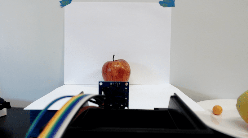
We now we will capture data to use to train our model in TensorFlow. First, choose a few different colored objects. We’ll use fruit, but you can use whatever you prefer.
Setting up the Arduino for data capture
Next we’ll use Arduino Create to program the Arduino board with an application object_color_capture.ino that samples color data from objects you place near it. The board sends the color data as a CSV log to your desktop machine over the USB cable.
To load the object_color_capture.ino application onto your Arduino board:
Connect your board to your laptop or PC with a USB cable
The Arduino board takes a male micro USB
Open object_color_capture.ino in Arduino Create by clicking this link
Your browser will open the Arduino Create web application (see GIF above).
Press OPEN IN WEB EDITOR
For existing users this button will be labeled ADD TO MY SKETCHBOOK
Press Upload & Save
This will take a minute
You will see the yellow light on the board flash as it is programmed
Open the serial Monitor
This opens the Monitor panel on the left-hand side of the web application
You will now see color data in CSV format here when objects are near the top of the board
Capturing data in CSV files for each object
For each object we want to classify we will capture some color data. By doing a quick capture with only one example per class we will not train a generalized model, but we can still get a quick proof of concept working with the objects you have to hand!
Say, for example, we are sampling an apple:
Reset the board using the small white button on top.
Keep your finger away from the sensor, unless you want to sample it!
The Monitor in Arduino Create will say ‘Serial Port Unavailable’ for a minute
You should then see Red,Green,Blue appear at the top of the serial monitor
Put the front of the board to the apple.
The board will only sample when it detects an object is close to the sensor and is sufficiently illuminated (turn the lights on or be near a window)
Move the board around the surface of the object to capture color variations
You will see the RGB color values appear in the serial monitor as comma separated data.
Capture at a few seconds of samples from the object
Copy and paste this log data from the Monitor to a text editor
Tip: untick AUTOSCROLL check box at the bottom to stop the text moving
Save your file as apple.csv
Reset the board using the small white button on top.
Do this a few more times, capturing other objects (e.g. banana.csv, orange.csv).
NOTE: The first line of each of the .csv files should read:
Red,Green,Blue
If you don’t see it at the top, you can just copy and paste in the line above.
Training the model
We will now use colab to train an ML model using the data you just captured in the previous section.
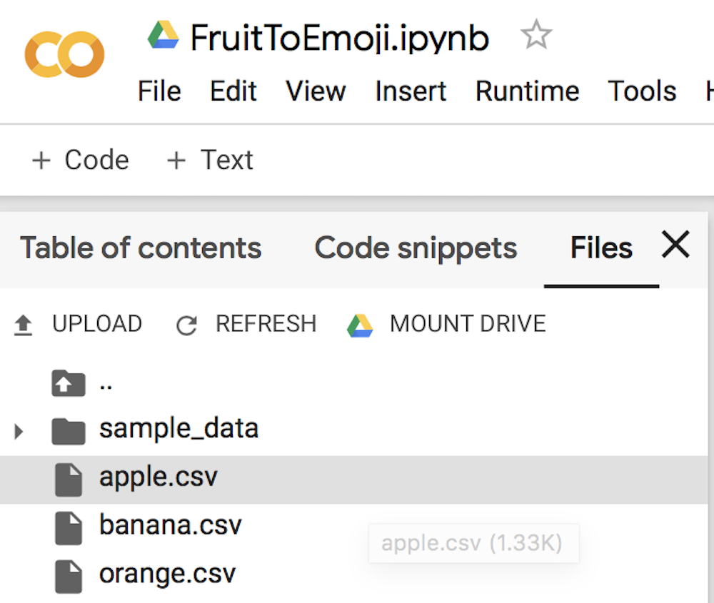
First open the FruitToEmoji Jupyter Notebook in colab
Follow the instructions in the colab
You will be uploading your *.csv files
Parsing and preparing the data
Training a model using Keras
Outputting TensorFlowLite Micro model
Downloading this to run the classifier on the Arduino
With that done you will have downloaded model.h to run on your Arduino board to classify objects!
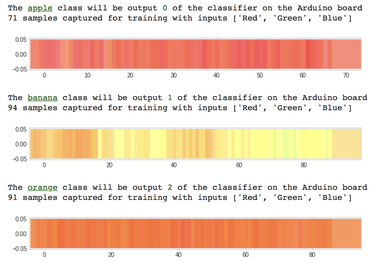
The colab will guide you to drop your .csv files into the file window, the result shown above
Normalized color samples captured by the Arduino board are graphed in colab
Program TensorFlow Lite Micro model to the Arduino board
Finally, we will take the model we trained in the previous stage and compile and upload to our Arduino board using Arduino Create.
Your browser will open the Arduino Create web application:
Press the OPEN IN WEB EDITOR button
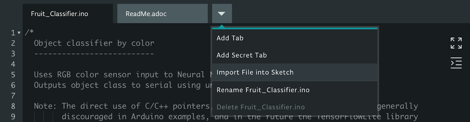
Import the model.h you downloaded from colab using Import File to Sketch:
Import the model.h you downloaded from colab
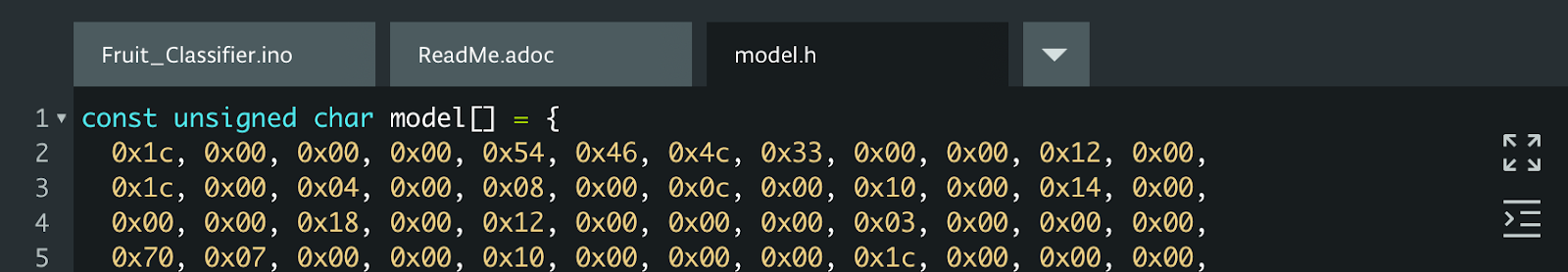
The model.h tab should now look like this
Compile and upload the application to your Arduino board
This will take a minute
When it’s done you’ll see this message in the Monitor:
Put your Arduino’s RGB sensor near the objects you trained it with
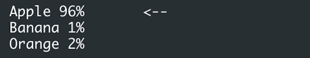
You will see the classification output in the Monitor:
Classifier output in the Arduino Create Monitor
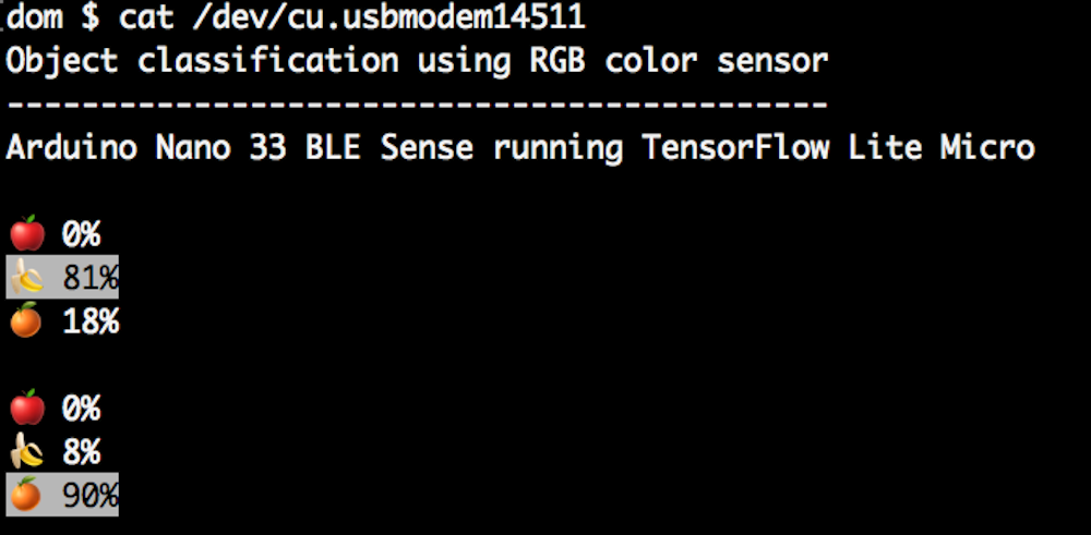
You can also edit the object_color_classifier.ino sketch to output emojis instead (we’ve left the unicode in the comments in code!), which you will be able to view in Mac OS X or Linux terminal by closing the web browser tab with Arduino Create in, resetting your board, and typing cat /cu/usb.modem[n].
Output from Arduino serial to Linux terminal using ANSI highlighting and unicode emojis
Learning more
The resources around TinyML are still emerging but there’s a great opportunity to get a head start and meet experts coming up 2-3 December 2019 in Mountain View, California at the Arm IoT Dev Summit. This includes workshops from Sandeep Mistry, Arduino technical lead for on-device ML and from Google’s Pete Warden and Daniel Situnayake who literally wrote the book on TinyML. You’ll be able to hang out with these experts and more at the TinyML community sessions there too. We hope to see you there!
Conclusion
We’ve seen a quick end-to-end demo of machine learning running on Arduino. The same framework can be used to sample different sensors and train more complex models. For our object by color classification we could do more, by sampling more examples in more conditions to help the model generalize. In future work, we may also explore how to run an on-device CNN. In the meantime, we hope this will be a fun and exciting project for you. Have fun!
This post was originally published by Sandeep Mistry and Dominic Pajakon the TensorFlow blog.
Arduino is on a mission to make machine learning simple enough for anyone to use. We’ve been working with the TensorFlow Lite team over the past few months and are excited to show you what we’ve been up to together: bringing TensorFlow Lite Micro to the Arduino Nano 33 BLE Sense. In this article, we’ll show you how to install and run several new TensorFlow Lite Micro examples that are now available in the Arduino Library Manager.
The first tutorial below shows you how to install a neural network on your Arduino board to recognize simple voice commands.
Example 1: Running the pre-trained micro_speech inference example.
Next, we’ll introduce a more in-depth tutorial you can use to train your own custom gesture recognition model for Arduino using TensorFlow in Colab. This material is based on a practical workshop held by Sandeep Mistry and Don Coleman, an updated version of which is now online.
If you have previous experience with Arduino, you may be able to get these tutorials working within a couple of hours. If you’re entirely new to microcontrollers, it may take a bit longer.
Example 2: Training your own gesture classification model.
We’re excited to share some of the first examples and tutorials, and to see what you will build from here. Let’s get started!
Note: The following projects are based on TensorFlow Lite for Microcontrollers which is currently experimental within the TensorFlow repo. This is still a new and emerging field!
Microcontrollers and TinyML
Microcontrollers, such as those used on Arduino boards, are low-cost, single chip, self-contained computer systems. They’re the invisible computers embedded inside billions of everyday gadgets like wearables, drones, 3D printers, toys, rice cookers, smart plugs, e-scooters, washing machines. The trend to connect these devices is part of what is referred to as the Internet of Things.
Arduino is an open-source platform and community focused on making microcontroller application development accessible to everyone. The board we’re using here has an Arm Cortex-M4 microcontroller running at 64 MHz with 1MB Flash memory and 256 KB of RAM. This is tiny in comparison to cloud, PC, or mobile but reasonable by microcontroller standards.
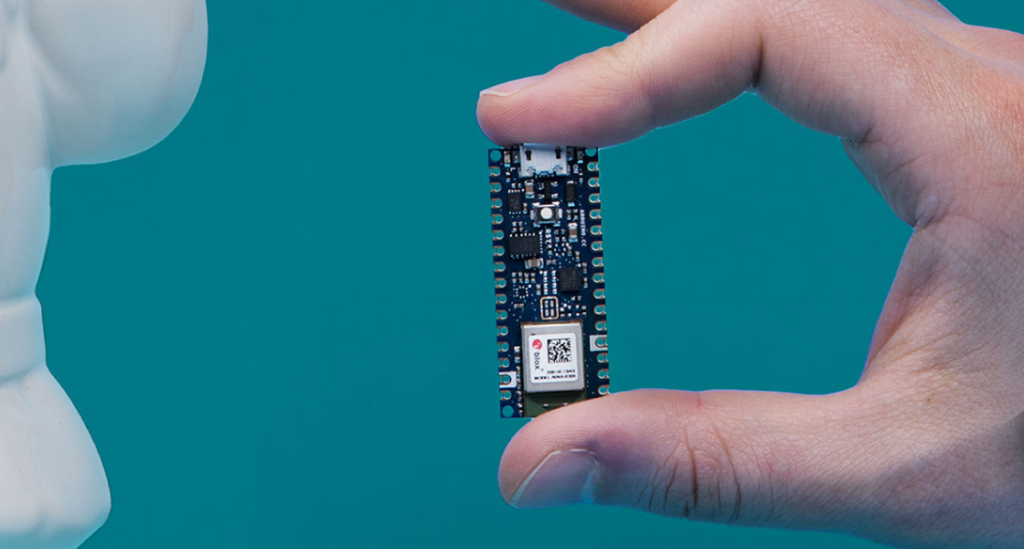
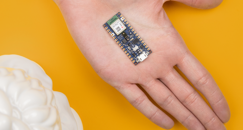
Arduino Nano 33 BLE Sense board is smaller than a stick of gum.
There are practical reasons you might want to squeeze ML on microcontrollers, including:
Function – wanting a smart device to act quickly and locally (independent of the Internet).
Cost – accomplishing this with simple, lower cost hardware.
Privacy – not wanting to share all sensor data externally.
Efficiency – smaller device form-factor, energy-harvesting or longer battery life.
There’s a final goal which we’re building towards that is very important:
Machine learning can make microcontrollers accessible to developers who don’t have a background in embedded development
On the machine learning side, there are techniques you can use to fit neural network models into memory constrained devices like microcontrollers. One of the key steps is the quantization of the weights from floating point to 8-bit integers. This also has the effect of making inference quicker to calculate and more applicable to lower clock-rate devices.
TinyML is an emerging field and there is still work to do – but what’s exciting is there’s a vast unexplored application space out there. Billions of microcontrollers combined with all sorts of sensors in all sorts of places which can lead to some seriously creative and valuable TinyML applications in the future.
What you need to get started
The Arduino Nano 33 BLE Sense has a variety of onboard sensors meaning potential for some cool TinyML applications:
Environmental – temperature, humidity and pressure
Light – brightness, color and object proximity
Unlike classic Arduino Uno, the board combines a microcontroller with onboard sensors which means you can address many use cases without additional hardware or wiring. The board is also small enough to be used in end applications like wearables. As the name suggests it has Bluetooth LE connectivity so you can send data (or inference results) to a laptop, mobile app or other BLE boards and peripherals.
Tip: Sensors on a USB stick – Connecting the BLE Sense board over USB is an easy way to capture data and add multiple sensors to single board computers without the need for additional wiring or hardware – a nice addition to a Raspberry Pi, for example.
TensorFlow Lite for Microcontrollers examples
The inference examples for TensorFlow Lite for Microcontrollers are now packaged and available through the Arduino Library manager making it possible to include and run them on Arduino in a few clicks. In this section we’ll show you how to run them. The examples are:
micro_speech – speech recognition using the onboard microphone
magic_wand – gesture recognition using the onboard IMU
person_detection – person detection using an external ArduCam camera
For more background on the examples you can take a look at the source in the TensorFlow repository. The models in these examples were previously trained. The tutorials below show you how to deploy and run them on an Arduino. In the next section, we’ll discuss training.
How to run the examples using Arduino Create web editor
Once you connect your Arduino Nano 33 BLE Sense to your desktop machine with a USB cable you will be able to compile and run the following TensorFlow examples on the board by using the Arduino Create web editor:
Compiling an example from the Arduino_TensorFlowLite library.
Focus on the speech recognition example: micro_speech
One of the first steps with an Arduino board is getting the LED to flash. Here, we’ll do it with a twist by using TensorFlow Lite Micro to recognise voice keywords. It has a simple vocabulary of “yes” and “no”. Remember this model is running locally on a microcontroller with only 256KB of RAM, so don’t expect commercial ‘voice assistant’ level accuracy – it has no Internet connection and on the order of 2000x less local RAM available.
Note the board can be battery powered as well. As the Arduino can be connected to motors, actuators and more this offers the potential for voice-controlled projects.
Running the micro_speech example.
How to run the examples using the Arduino IDE
Alternatively you can use try the same inference examples using Arduino IDE application.
First, follow the instructions in the next section Setting up the Arduino IDE.
In the Arduino IDE, you will see the examples available via the File > Examples > Arduino_TensorFlowLite menu in the ArduinoIDE.
Select an example and the sketch will open. To compile, upload and run the examples on the board, and click the arrow icon:
For advanced users who prefer a command line, there is also the arduino-cli.
Training a TensorFlow Lite Micro model for Arduino
Gesture classification on Arduino BLE 33 Nano Sense, output as emojis.
Next we will use ML to enable the Arduino board to recognise gestures. We’ll capture motion data from the Arduino Nano 33 BLE Sense board, import it into TensorFlow to train a model, and deploy the resulting classifier onto the board.
The idea for this tutorial was based on Charlie Gerard’s awesome Play Street Fighter with body movements using Arduino and Tensorflow.js. In Charlie’s example, the board is streaming all sensor data from the Arduino to another machine which performs the gesture classification in Tensorflow.js. We take this further and “TinyML-ifiy” it by performing gesture classification on the Arduino board itself. This is made easier in our case as the Arduino Nano 33 BLE Sense board we’re using has a more powerful Arm Cortex-M4 processor, and an on-board IMU.
We’ve adapted the tutorial below, so no additional hardware is needed – the sampling starts on detecting movement of the board. The original version of the tutorial adds a breadboard and a hardware button to press to trigger sampling. If you want to get into a little hardware, you can follow that version instead.
Setting up the Arduino IDE
Following the steps below sets up the Arduino IDE application used to both upload inference models to your board and download training data from it in the next section. There are a few more steps involved than using Arduino Create web editor because we will need to download and install the specific board and libraries in the Arduino IDE.
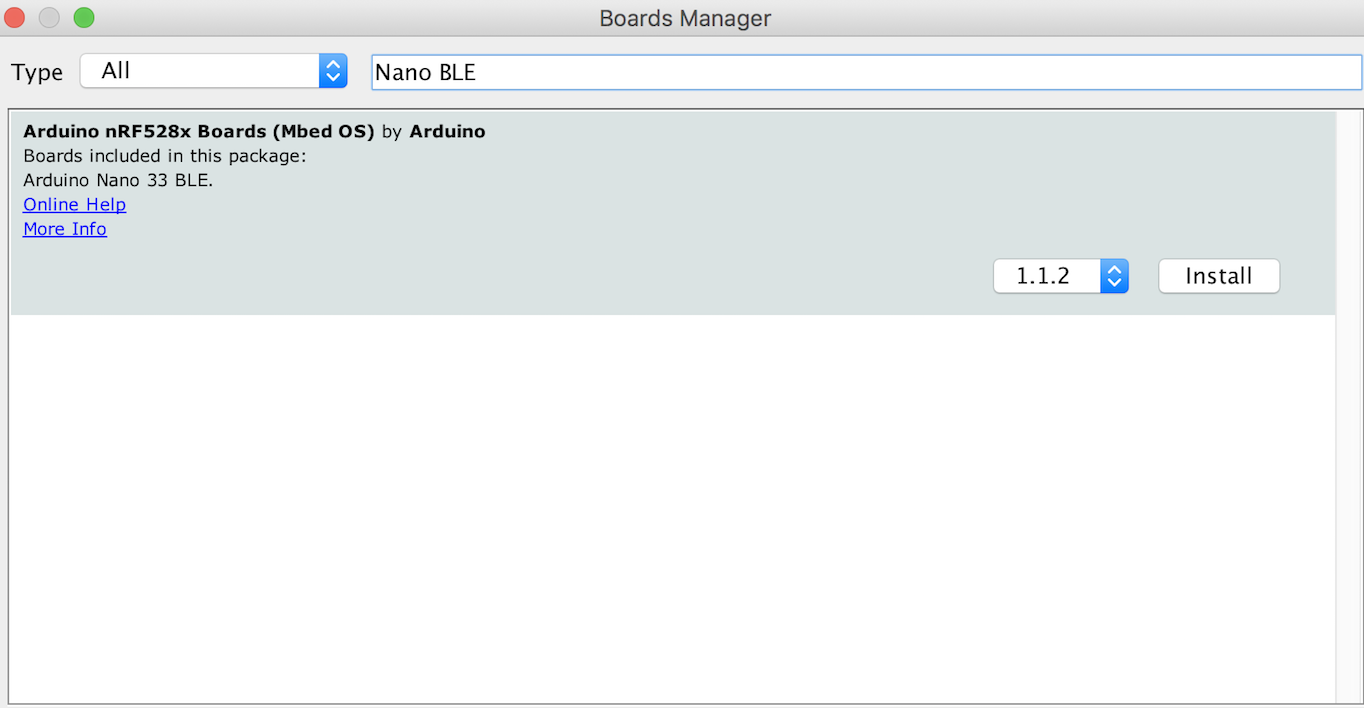
In the Arduino IDE menu select Tools > Board > Boards Manager…
Search for “Nano BLE” and press install on the board
It will take several minutes to install
When it’s done close the Boards Manager window
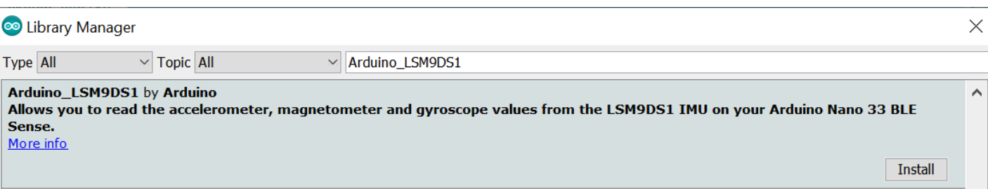
Now go to the Library Manager Tools > Manage Libraries…
Search for and install the Arduino_TensorFlowLite library
Next search for and install the Arduino_LSM9DS1 library:
Finally, plug the micro USB cable into the board and your computer
Choose the board Tools > Board > Arduino Nano 33 BLE
Choose the port Tools > Port > COM5 (Arduino Nano 33 BLE)
Note that the actual port name may be different on your computer
First, we need to capture some training data. You can capture sensor data logs from the Arduino board over the same USB cable you use to program the board with your laptop or PC.
Arduino boards run small applications (also called sketches) which are compiled from .ino format Arduino source code, and programmed onto the board using the Arduino IDE or Arduino Create.
We’ll be using a pre-made sketch IMU_Capture.ino which does the following:
Monitor the board’s accelerometer and gyroscope
Trigger a sample window on detecting significant linear acceleration of the board
Sample for one second at 119Hz, outputting CSV format data over USB
Loop back and monitor for the next gesture
The sensors we choose to read from the board, the sample rate, the trigger threshold, and whether we stream data output as CSV, JSON, binary or some other format are all customizable in the sketch running on the Arduino. There is also scope to perform signal preprocessing and filtering on the device before the data is output to the log – this we can cover in another blog. For now, you can just upload the sketch and get sampling.
To program the board with this sketch in the Arduino IDE:
Compile and upload it to the board with Sketch > Upload
Visualizing live sensor data log from the Arduino board
With that done we can now visualize the data coming off the board. We’re not capturing data yet this is just to give you a feel for how the sensor data capture is triggered and how long a sample window is. This will help when it comes to collecting training samples.
In the Arduino IDE, open the Serial Plotter Tools > Serial Plotter
If you get an error that the board is not available, reselect the port:
Tools > Port > portname (Arduino Nano 33 BLE)
Pick up the board and practice your punch and flex gestures
You’ll see it only sample for a one second window, then wait for the next gesture
You should see a live graph of the sensor data capture (see GIF below)
Arduino IDE Serial Plotter will show a live graph of CSV data output from your board.
When you’re done be sure to close the Serial Plotter window – this is important as the next step won’t work otherwise.
Capturing gesture training data
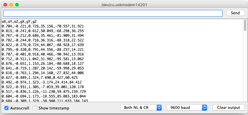
To capture data as a CSV log to upload to TensorFlow, you can use Arduino IDE > Tools > Serial Monitor to view the data and export it to your desktop machine:
Reset the board by pressing the small white button on the top
Pick up the board in one hand (picking it up later will trigger sampling)
In the Arduino IDE, open the Serial Monitor Tools > Serial Monitor
If you get an error that the board is not available, reselect the port:
Tools > Port > portname (Arduino Nano 33 BLE)
Make a punch gesture with the board in your hand (Be careful whilst doing this!)
Make the outward punch quickly enough to trigger the capture
Return to a neutral position slowly so as not to trigger the capture again
Repeat the gesture capture step 10 or more times to gather more data
Copy and paste the data from the Serial Console to new text file called punch.csv
Clear the console window output and repeat all the steps above, this time with a flex gesture in a file called flex.csv
Make the inward flex fast enough to trigger capture returning slowly each time
Note the first line of your two csv files should contain the fields aX,aY,aZ,gX,gY,gZ.
Linux tip: If you prefer you can redirect the sensor log output from the Arduino straight to a .csv file on the command line. With the Serial Plotter / Serial Monitor windows closed use:
$ cat /dev/cu.usbmodem[nnnnn] > sensorlog.csv
Training in TensorFlow
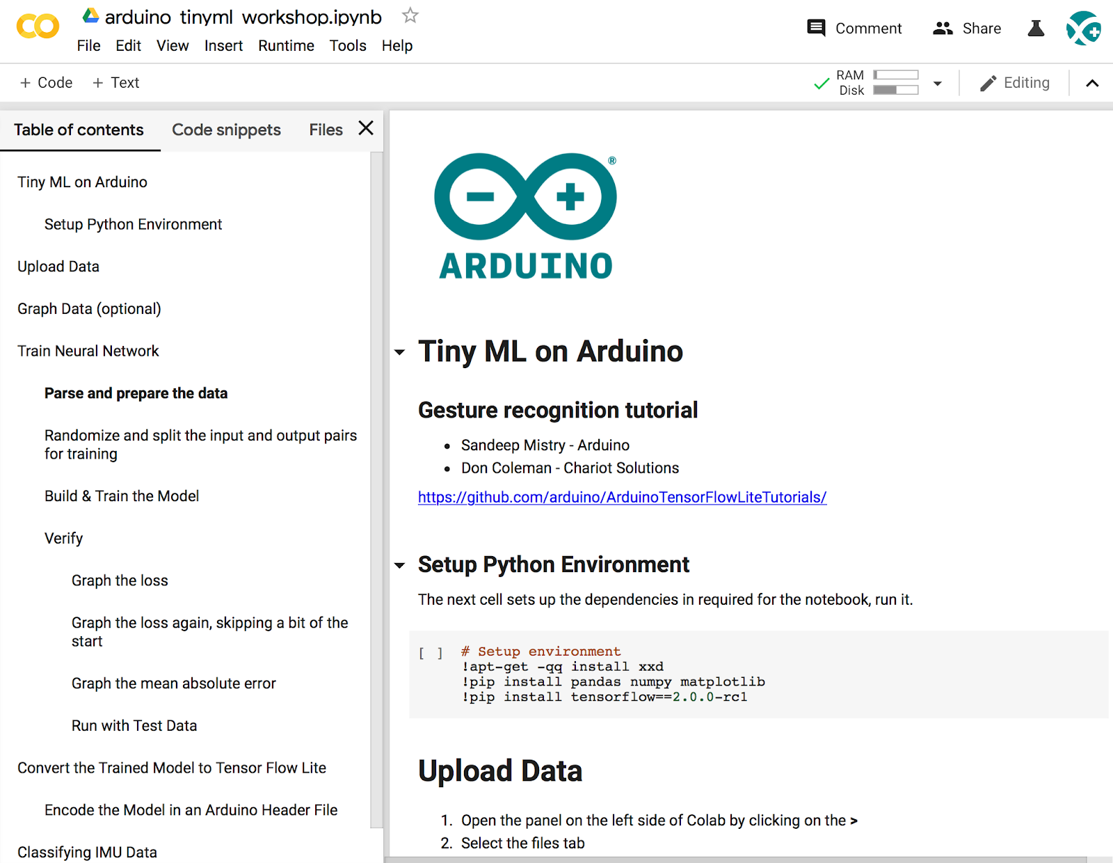
We’re going to use Google Colab to train our machine learning model using the data we collected from the Arduino board in the previous section. Colab provides a Jupyter notebook that allows us to run our TensorFlow training in a web browser.
Arduino gesture recognition training colab.
The colab will step you through the following:
Set up Python environment
Upload the punch.csv and flex.csv data
Parse and prepare the data
Build and train the model
Convert the trained model to TensorFlow Lite
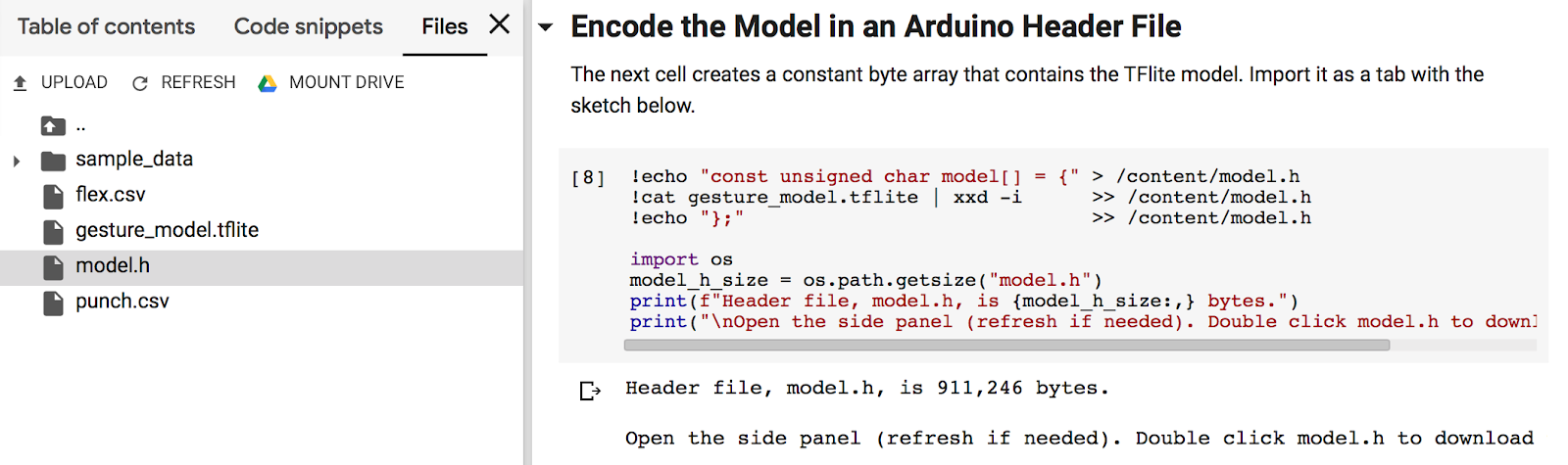
Encode the model in an Arduino header file
The final step of the colab is generates the model.h file to download and include in our Arduino IDE gesture classifier project in the next section:
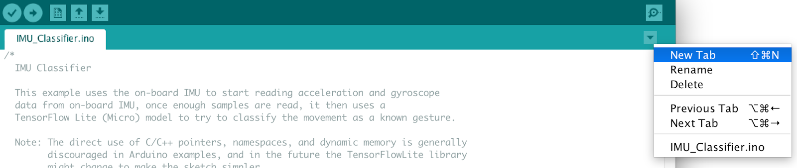
Create a new tab in the IDE. When asked name it model.h
Open the model.h tab and paste in the version you downloaded from Colab
Upload the sketch: Sketch > Upload
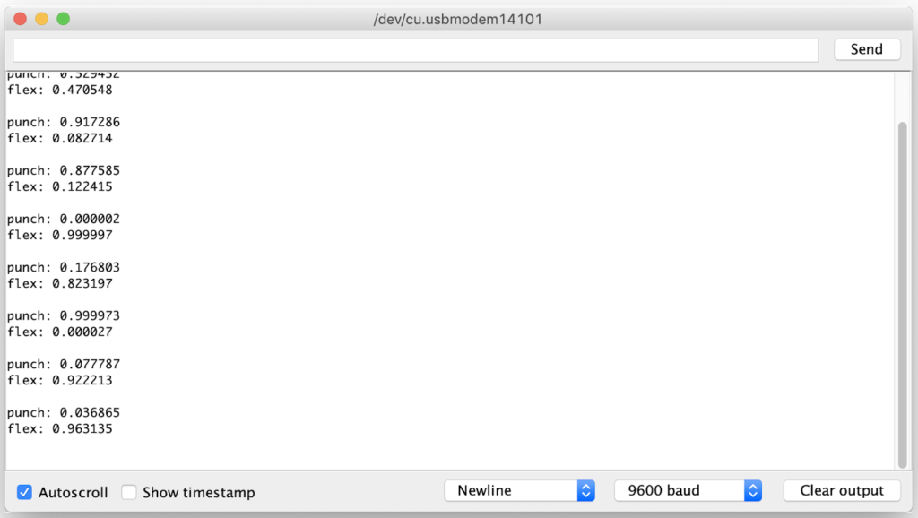
Open the Serial Monitor: Tools > Serial Monitor
Perform some gestures
The confidence of each gesture will be printed to the Serial Monitor (0 = low confidence, 1 = high confidence)
Congratulations you’ve just trained your first ML application for Arduino!
For added fun the Emoji_Button.ino example shows how to create a USB keyboard that prints an emoji character in Linux and macOS. Try combining the Emoji_Button.ino example with the IMU_Classifier.ino sketch to create a gesture controlled emoji keyboard.
Conclusion
It’s an exciting time with a lot to learn and explore in TinyML. We hope this blog has given you some idea of the potential and a starting point to start applying it in your own projects. Be sure to let us know what you build and share it with the Arduino community.
This post is from Sandeep Mistry, Senior Software Engineer at Arduino.
Today, we are pleased to announce BLE (Bluetooth Low Energy) central support in v1.1.0 of the ArduinoBLE library. This major feature addition allows your Arduino board to scan for and connect to BLE peripheral devices. With one simple library, you can now use BLE to directly connect your Arduino board to:
A smartphone, tablet, laptop or PC
BLE peripherals (e.g. TI SensorTag) – NEW!
Another Arduino board – NEW!
The ArduinoBLE library and new BLE central feature are supported on the following Arduino boards:
Prior to this release, Arduino only officially supported BLE peripheral functionality on these boards. A BLE peripheral is typically used to expose some sensor data or actuators to another device BLE central capable device such as a smartphone or PC. With the new BLE central functionality, you’ll be able to wirelessly connect two boards together for communication or connect to a third party BLE peripheral, such as a TI SensorTag.
We think that the ArduinoBLE library is much easier to use than anything else out there and are excited to see what you build with this new capability!
The development journey
Back in 2015, the Arduino 101 was released, based on the Curie module developed by Intel. It was the first official Arduino board with on-board BLE support. The CurieBLE library initially only supported BLE peripheral mode.
After launch, the Arduino and Intel teams worked together to design an Arduino friendly BLE API that supported both BLE Peripheral and Central functionality. This was released later in 2016 in the v2.0 of the Arduino core for Arduino 101.
The BLE features of the 101 were also incorporated into the CTC 101 kit in many classrooms around the world. Students used smartphones or tablets for exercises in the kit to interact with project based lessons running on the board. Unfortunately, Intel decided to stop producing the Curie module in 2017, bringing the Arduino 101 board to end of life.
Last year, at Maker Faire Bay Area 2018, Arduino launched two new boards: the MKR WiFi 1010 and Uno WiFi Rev.2. Both boards use the u-blox NINA-W102 as a 2.4 GHz wireless module. Initially both boards only supported WiFi using the WiFiNINA library. However, the ESP32 chip inside the u-blox NINA-W102 supports Bluetooth classic and BLE as well.
Later in 2018, the Arduino core team was tasked with adding BLE support to the MKR WiFi 1010 board so that it could be used with the upcoming Arduino Science Kit Physics Lab product. The Science Kit Physics Lab product is another educational kit, targeted for students in the classroom. We had several choices to move forward, including:
Bridging the ESP-IDF’s BLE API’s via RPC to the main MCU that sketches run on
Basing things on the industry standard Bluetooth HCI protocol and investing in a Bluetooth HCI host stack as an Arduino library
The first option above was expected to take an equal amount of time to the second, but also would make the BLE library exposed to users highly dependent on the underlying firmware running on the ESP32. It was also not as portable to other chip sets in the future. Thus, ArduinoBLE was created. The NINA firmware only needed small change to bridge its virtual Bluetooth HCI controller to the UART pins of the module.
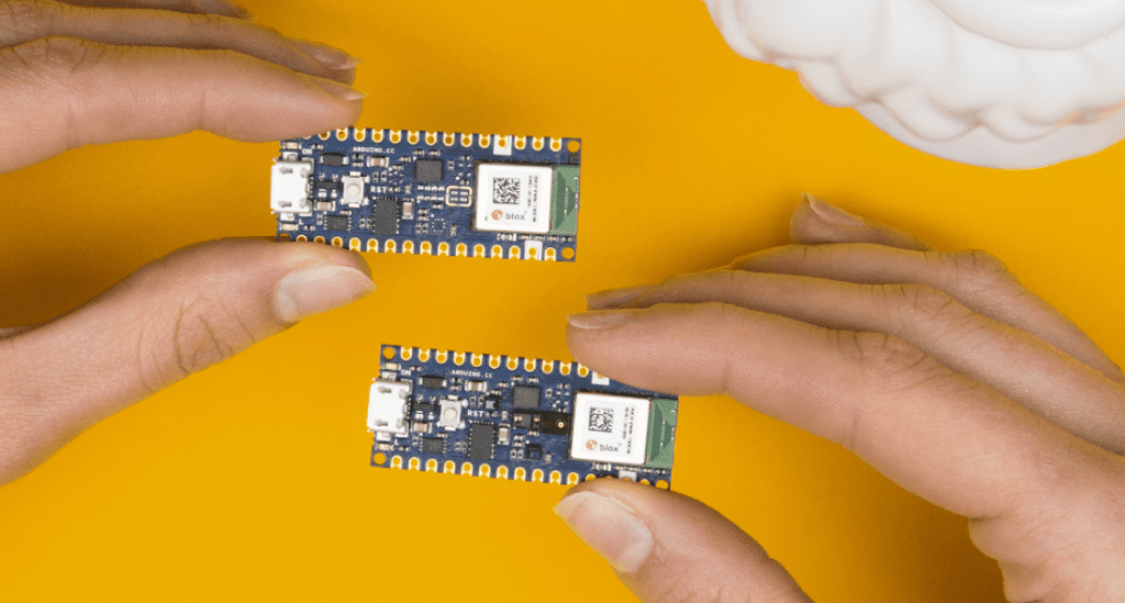
Earlier this year, we released the Arduino Nano 33 IoT and Arduino Nano 33 BLE boards. Since the Arduino Nano 33 IoT uses the same chipset as the MKR WiFi 1010, things worked out of the box. For the Nano 33 BLE, which is based on the Nordic nRF52840 chip, a new Arduino core was developed for this board based on mbed OS (see this blog post for more info). mbed OS includes a radio stack called Cordio, which provides both a Bluetooth HCI link controller and HCI host. Creating a single C++ class that interfaced with Cordio’s Bluetooth HCI link layer allowed us to re-use 95%+ of ArduinoBLE on this board. 🙂
After the Nano 33 BLE started shipping, there was even more demand for BLE central support. So, development for feature was scheduled and is now available. It combines the API designed for the Arduino 101 in CurieBLE ported on top of ArduinoBLE’s Bluetooth HCI host stack.
Many thanks to Tom Igoe, one of the co-founders of Arduino, for providing feedback on the official Arduino BLE libraries throughout the years.
We are excited to announce a new partnership with Chirp, a London-based company on a mission to simplify connectivity using sound. Chirp’s machine-to-machine communications software enables any device with a loudspeaker or microphone to exchange data via inaudible sound waves.
Starting today, our Chirp integration will allow Arduino-powered projects to send and receive data wirelessly over sound waves, using just microphones and loudspeakers. Thanks to some compatible libraries included in the official Arduino Library Manager and in the Arduino Create — as well as further comprehensive documentation, tutorials and technical support — it will be easy for anyone to add data-over-sound capabilities to their Arduino projects.
Creative applications of Arduino and Chirp include, but certainly are not limited to:
Triggering events from YouTube audio
Securely unlocking a smart lock with sound
Sending Wi-Fi credentials to bring offline devices onto a Wi-Fi network
Having a remote control that only interacts with the gadgets in the same room as you
“Connectivity is a fundamental asset for our users, as the demands of IoT uptake require devices to communicate information seamlessly and with minimal impact for the end user. Chirp’s data-over-sound solution equips our boards with robust data transmission, helping us to deliver enhanced user experiences whilst increasing the capabilities of our hardware at scale,” said Massimo Banzi, Arduino co-founder.
“Sound is prevailing as a highly effective and versatile means of seamless data transmission, presenting developers with a simple to use, software-defined solution which can connect devices. Working with Arduino to extend the integration of data-over-sound across its impressive range of boards will not only increase the reach of Chirp’s technology, but provide many more developers with an accessible and easily integrated connectivity solution to help them drive their projects forward in all purposes and environments. We can’t wait to see what the Arduino community builds,” commented James Nesfield, Chirp CEO.
To learn how to send data with sound with an Arduino Nano 33 BLE Sense and Chirp, check out this tutorial and visit Chirp website here.
The Arduino Nano 33 BLE and BLE Sense are officially available!
Arduino Team — July 31st, 2019
The wait is finally over, the new Arduino Nano 33 BLE and BLE Sense are both available. The boards have been manufactured, delivered to our warehouses, and will ship starting in mid-August.
These new boards are an exciting addition to our product line — based on the powerful Nordic nRF52840 Bluetooth SoC, a Cortex-M4F Arm processor with advanced Bluetooth capabilities.
Together with the u-blox NINA B306 module, the BLE Sense in particular delivers a lot of value through its impressive array of onboard sensors: a 9-axis inertial measurement unit (IMU), temperature, pressure, humidity, light, color, and even gesture sensors, as well as a microphone, that are managed through our specialized libraries.
To coincide with the launch of the new boards we’re making the official Arduino programming support for this processor available — in Arduino slang what we call a “Core.” The ArduinoCore-nRF528x-mbedos that you will be able to add to your Arduino IDE in a few hours is based on the Arm Mbed OS Real-Time Operating System. This is an amazing addition to the Arduino software stack because now you can transparently take full advantage of a powerful RTOS while using all your existing Arduino programming knowledge. This is an significant advancement for the platform as it opens the door to creating more sophisticated and mission critical applications on the Arduino software framework.
For a more in-depth discussion about the new Arduino Core, read the blog post written by Martino Facchin, who is in charge of the firmware development team, where explains all the details of the implementation and how we came to this decision.
Um dir ein optimales Erlebnis zu bieten, verwenden wir Technologien wie Cookies, um Geräteinformationen zu speichern und/oder darauf zuzugreifen. Wenn du diesen Technologien zustimmst, können wir Daten wie das Surfverhalten oder eindeutige IDs auf dieser Website verarbeiten. Wenn du deine Einwillligung nicht erteilst oder zurückziehst, können bestimmte Merkmale und Funktionen beeinträchtigt werden.
Funktional
Immer aktiv
Die technische Speicherung oder der Zugang ist unbedingt erforderlich für den rechtmäßigen Zweck, die Nutzung eines bestimmten Dienstes zu ermöglichen, der vom Teilnehmer oder Nutzer ausdrücklich gewünscht wird, oder für den alleinigen Zweck, die Übertragung einer Nachricht über ein elektronisches Kommunikationsnetz durchzuführen.
Vorlieben
Die technische Speicherung oder der Zugriff ist für den rechtmäßigen Zweck der Speicherung von Präferenzen erforderlich, die nicht vom Abonnenten oder Benutzer angefordert wurden.
Statistiken
Die technische Speicherung oder der Zugriff, der ausschließlich zu statistischen Zwecken erfolgt.Die technische Speicherung oder der Zugriff, der ausschließlich zu anonymen statistischen Zwecken verwendet wird. Ohne eine Vorladung, die freiwillige Zustimmung deines Internetdienstanbieters oder zusätzliche Aufzeichnungen von Dritten können die zu diesem Zweck gespeicherten oder abgerufenen Informationen allein in der Regel nicht dazu verwendet werden, dich zu identifizieren.
Marketing
Die technische Speicherung oder der Zugriff ist erforderlich, um Nutzerprofile zu erstellen, um Werbung zu versenden oder um den Nutzer auf einer Website oder über mehrere Websites hinweg zu ähnlichen Marketingzwecken zu verfolgen.