Schlagwort: micro
-

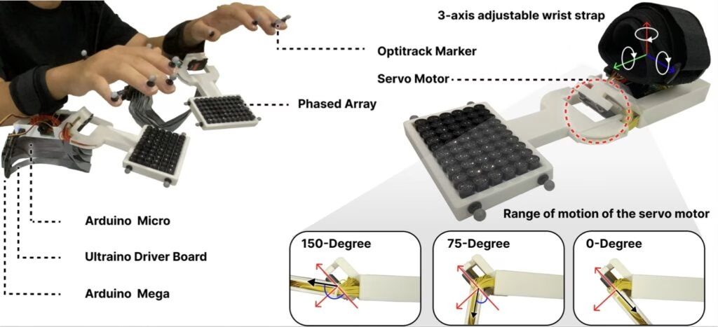
This novel wearable provides touchless haptic feedback for VR typing
Reading Time: 2 minutesOne reason that fans prefer mechanical keyboards over membrane alternatives is that mechanical key switches provide a very noticeable tactile sensation at the moment a key press registers. Whether consciously or not, users notice that and stop pressing the key all the way through the maximum travel — reducing strain and RSI…
-

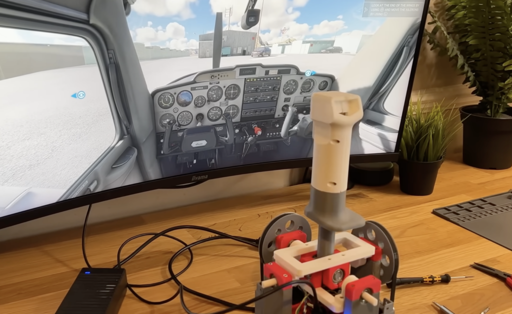
This custom flight joystick provides force feedback with stepper motors
Reading Time: 2 minutesThe joysticks found on ordinary controllers are quite simple, and as a result, they fail to provide much in the way of haptic feedback for the user. This is especially tough in racing or flight simulator games where making sharp turns should require a greater amount of force. YouTuber zeroshot’s project aimed…
-

Voice-enabled controller makes video games more accessible
Reading Time: 2 minutesAlmost all modern video games require either a gamepad or a keyboard and mouse, which means that they’re inaccessible to many people with disabilities that affect manual dexterity. Bob Hammell’s voice-enabled controller lets some of those people experience the joy of video games. This is a simplified video game controller with a…
-

Building a custom broom controller for Hogwarts Legacy
Reading Time: 2 minutesFor fans of Harry Potter, Hogwarts Legacy is a dream game. It drops you into the Potterverse where you can become a wizard, casting spells and riding brooms to your heart’s content. It is a very immersive game, but you lose some of that immersion when you realize you’re actually just pushing buttons on…
-

Bolt Bots are perfect for aspiring roboticists
Reading Time: 2 minutesWhile it is easier now than ever before, getting into robotics is still daunting. In the past, aspiring roboticists were limited by budget and inaccessible technology. But today the challenge is an overwhelming abundance of different options. It is hard to know where to start, which is why Saul designed a set…
-

An open-source, breath-controlled MIDI device
Reading Time: 2 minutesThe simplest MIDI (Musical Instrument Digital Interface) input devices use good ol’ fashioned buttons: push a button and the device sends a MIDI message to trigger a specific note. But that control scheme doesn’t replicate the flexibility of a real instrument very well, because a standard button is a binary mechanism. To…
-

This 3D-printed robot is made for sumo battle tournaments
Reading Time: 2 minutesWhile the majority of makers are unable to afford the fancy equipment and components that go into modern state-of-the-art battle robots, there do exist lesser-known tournaments for more DIY designs, including sumo robot battles. Instructables user noclaf8810373’s design incorporates all of the high-powered components one would expect to find, along with an innovative defense mechanism. Construction…
-

Wesley Kagan’s PorscheKart project returns with a new Arduino-powered F1 steering wheel
Reading Time: 2 minutesAs part of his ongoing PorscheKart project, YouTuber Wesley Kagan wanted a better way to steer his V12 custom-built race car, as the previous wheel was simply a mechanical linkage to the front steering. Instead, this new version would closely mimic the layout and functionality of an actual Formula 1 wheel, complete with…
-

Zen sand garden in a suitcase doubles as MIDI controller
Reading Time: 3 minutesAt the shallow end of the pool, a MIDI (musical instrument digital interface) controller can be as simple as a handful of buttons that correspond to different notes. But even as one wades into the deep end of the pool, MIDI controllers tend to still look like hunks of plastic with some…
-
Classic Macintosh gets a massive ePaper display
Reading Time: 2 minutesArduino Team — August 24th, 2022 The original Apple Macintosh computer, launched in 1984, was fundamental for ushering in GUIs (graphical user interfaces). It wasn’t the first personal computer to feature a GUI operating system and the concurrent Apple II still retained a more traditional command line interface for years, but we…
-

Adding a battery gauge to a Citroën C-Zero electric car
Reading Time: 2 minutesArduino Team — August 3rd, 2022 The Citroën C-Zero is an electric city card sold in the European market. It is a rebadged Mitsubishi i-MiEV, which is based on the Mitsubishi i kei car platform. Kei cars, in Japan, are a special class that receive government and insurance benefits for being so…
-
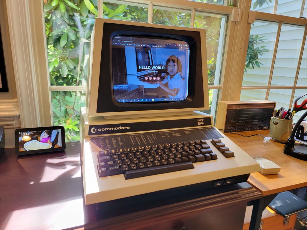
Converting a Commodore PET into a USB docking station
Reading Time: 2 minutesArduino Team — July 22nd, 2022 The Commodore 64 is one of the most iconic computers of all time and it is Commodore’s best known model. But Commodore made many other well-loved models, including the VIC-20, the Amiga, and the PET. The Commodore PET 64, which Commodore released late in the model…
-

Get fit while you scroll TikTok with the PELOTok!
Reading Time: 2 minutesArduino Team — June 2nd, 2022 The convenience of smartphones combined with our infinitely scrolling social media feeds has led to some less-than-ideal results, including the fact that a person can sit down and be entertained for hours without even realizing it. This inactivity and lack of exercise can lead to a…
-
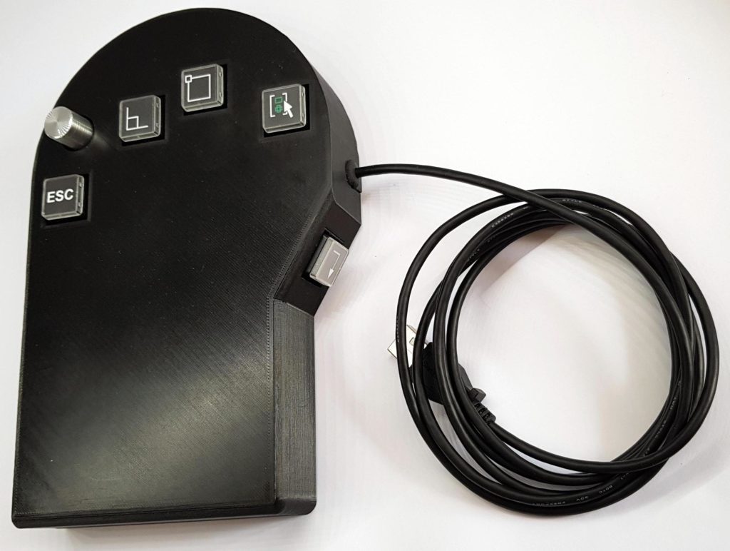
MacroMitt increases AutoCAD productivity
Reading Time: 2 minutesMacroMitt increases AutoCAD productivity Arduino Team — May 25th, 2022 AutoCAD is conventional 2D CAD (drafting) software that still contains many “legacy” features that you won’t find in modern 3D CAD programs. One of those features is the command line, in which users can type short commands to perform various functions or…
-

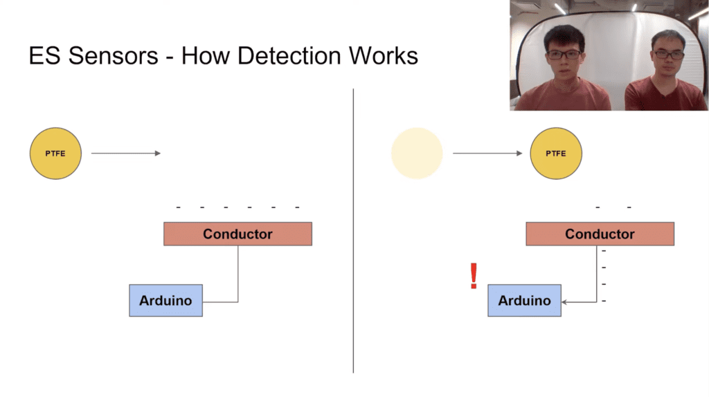
ESsense turns an ordinary conductor into a contactless motion sensor
Reading Time: 2 minutesArduino Team — May 23rd, 2022 When imagining motion sensors, devices such as accelerometers, infrared detectors, and LiDAR units probably come to mind. But due to the complexity and oftentimes high costs of these parts, researchers Joseph Liew and Keng Wei Ng from the National University of Singapore wanted to create a…
-

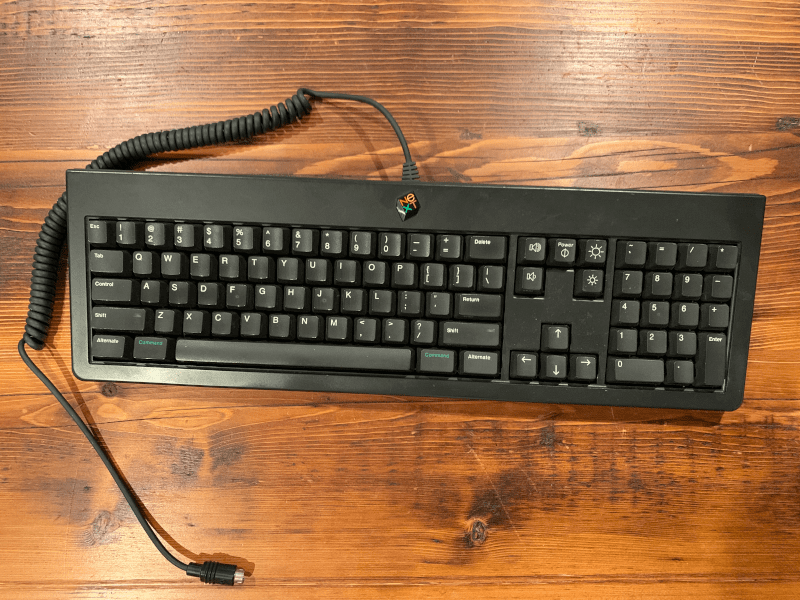
Reverse engineering an ’80s NeXT keyboard
Reading Time: 2 minutesReverse engineering an ’80s NeXT keyboard Arduino Team — January 27th, 2022 Working with vintage computer technology can feel a bit like the digital equivalent of archeology. Documentation is often limited or altogether absent today — if it was ever even public in the first place. So you end up reverse engineering…
-

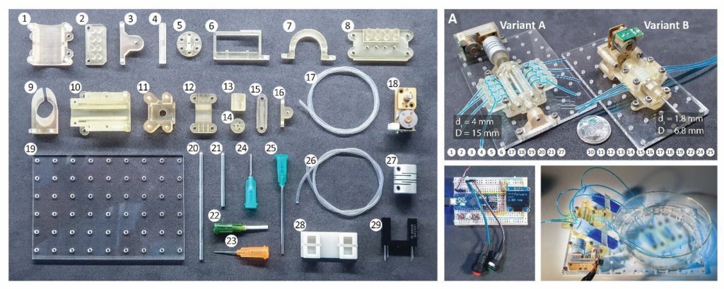
This 3D-printed, Arduino-controlled kit makes microfluidic pumps more accessible
Reading Time: 2 minutesArduino Team — December 27th, 2021 In circumstances where extreme precision is required when dealing with the movement of microscopic amounts of liquids, such as lab-on-a-chip (LoC) and organs-on-a-chip (OoC) systems, obtaining a pump that is both cheap and accurate is nearly impossible since they often cost several thousands of dollars to…
-
Converting a Fat Cat plushie into a controller for Final Fantasy XIV
Reading Time: < 1 minuteArduino Team — November 26th, 2021 Mounts in the video game Final Fantasy XIV act like how cars or horses do in our world since they allow players to travel around the map much faster than would otherwise be possible. But even better, mounts are ways to express personality and have…
-

Scale up your dragon costume with wings that extend, flap and retract
Reading Time: 2 minutesArduino Team — November 1st, 2021 This year for Halloween, Quint BUILDs wanted to make something special for his daughter’s costume. Quint’s idea was to design and fabricate a pair of mechatronic dragon wings that can mount to a user’s back and move in three different modes by utilizing a set of pneumatic air cylinders. …
-

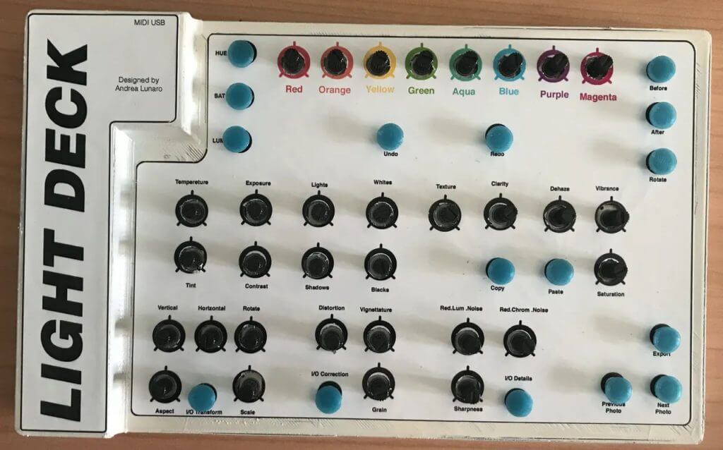
Light Deck is a MIDI Lightroom controller
Reading Time: 2 minutesArduino Team — October 21st, 2021 Using Adobe Lightroom can be a tedious process, especially for those who don’t have their keyboards set up with a hundred macro shortcuts. Andrea Lunaro wanted to make this process easier by constructing a large, physical bank of buttons and potentiometers that can be used to perform…
-

Play SNES SPC audio files from your browser using original hardware and Arduino
Reading Time: 2 minutesArduino Team — August 9th, 2021 Listening to those classic 16-bit sounds from the ’90s video game era brings back a wave of nostalgia for those who grew up with a console. On the Super Nintendo Entertainment System, outputting sound was accomplished by an integrated circuit called the SNES Audio Processing Unit…
-
This dad built an adaptive USB keyboard for his son and other kids with muscular conditions
Reading Time: 2 minutesArduino Team — June 3rd, 2021 Having a disability can severely impact one’s ability to perform tasks that others do regularly, such as eating, walking, or even speaking. One maker by the name of ‘gtentacle‘ has a son who needs to use a ventilator constantly in order to breathe as he suffers…