Schlagwort: mega
-

James Bruton’s 512 LED DJ helmet adds more glow to his Performance Robots show
Reading Time: 2 minutesJames Bruton’s 512 LED DJ helmet adds more glow to his Performance Robots show Arduino Team — November 13th, 2019 If you’ve ever thought that your musical performance needed more LEDs, then James Bruton’s DJ helmet may be just the thing for you. The YouTuber’s wearable device is built on the base…
-

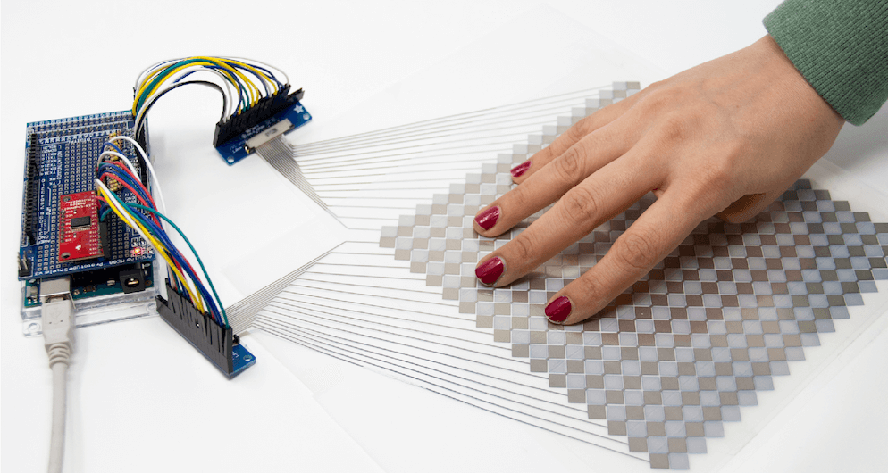
Rapidly create your own capacitive multi-touch sensors with this kit
Reading Time: 2 minutesRapidly create your own capacitive multi-touch sensors with this kit Arduino Team — November 13th, 2019 You likely use touchscreens every day when interacting with your phone — perhaps even to read this article — but prototyping your own capacitive matrix is unfortunately out of reach for most makers and electronics novices.…
-

This suitcase game lets you bring the escape room experience anywhere
Reading Time: 2 minutesThis suitcase game lets you bring the escape room experience anywhere Arduino Team — November 12th, 2019 To experience an escape room, you normally need a rather large dedicated space. This project, however, by creator Jason R, takes this physical clue-solving concept and shrinks it down to fit within a small suitcase!…
-

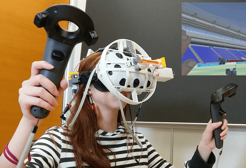
ElastImpact brings a bit more realism to VR
Reading Time: 2 minutesElastImpact brings a bit more realism to VR Arduino Team — November 11th, 2019 If you’ve ever used a VR system and thought what was really missing is the feeling of being hit in the face, then a team researchers at the National Taiwan University may hold just the solution. ElastImpact takes the…
-

Competition robot picks up (almost) all the balls
Reading Time: < 1 minuteCompetition robot picks up (almost) all the balls Arduino Team — November 9th, 2019 For the Warman Design and Build Competition in Sydney last month, Redditor ‘Travman_16 and team created an excellent Arduino-powered entry. The contest involved picking up 20 payloads (AKA balls) from a trough, and delivering them to a…
-

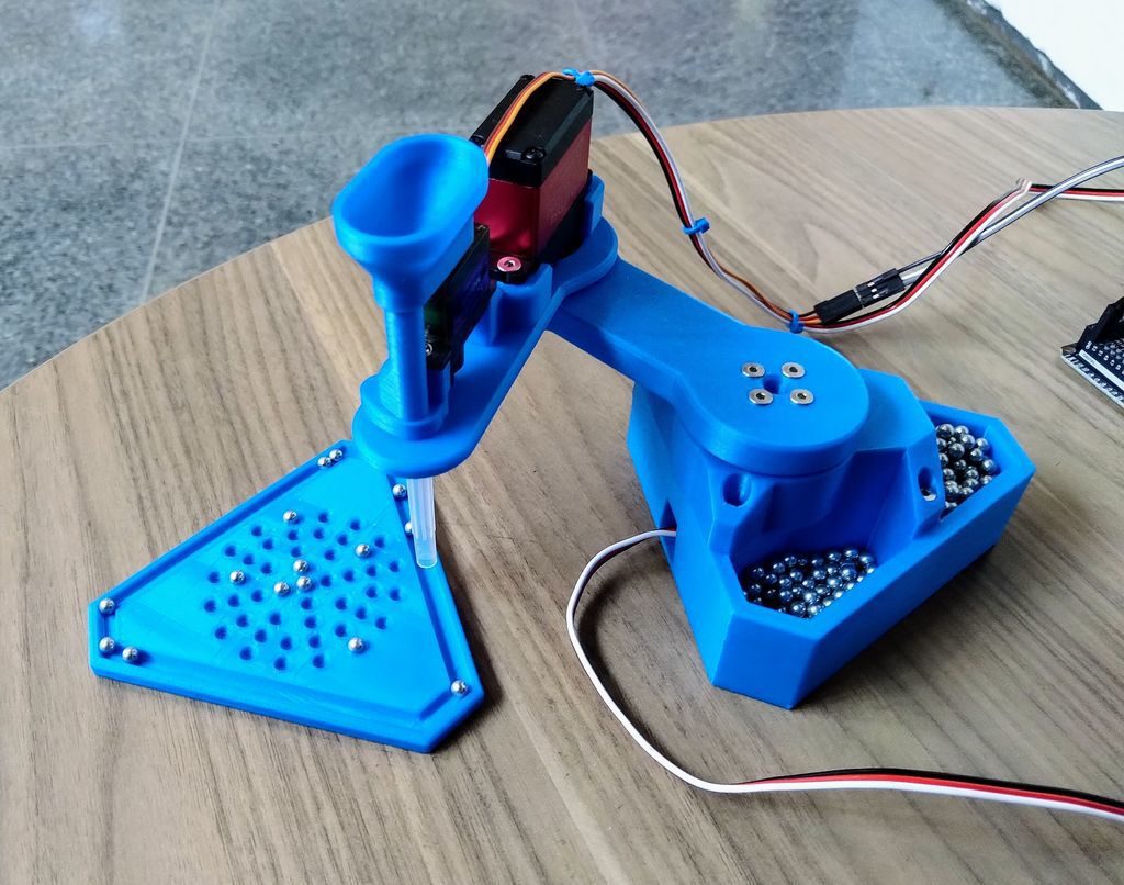
This 3D-printed SCARA robot dispenses ball bearings
Reading Time: < 1 minuteThis 3D-printed SCARA robot dispenses ball bearings Arduino Team — November 8th, 2019 SCARA robots are often used in industrial settings to move components in the proper location. In order to demonstrate the concept to students, Nicholas Schwankl has come up with a simple unit that employs three servos and 3D-printed…
-

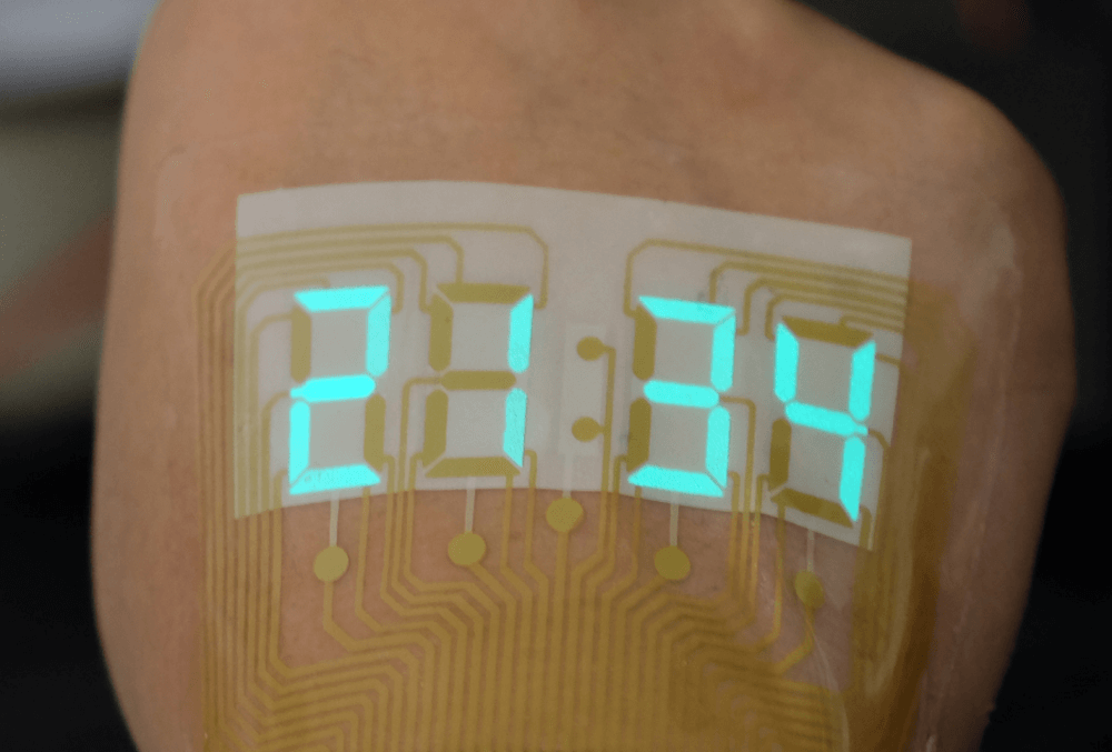
Check your run time on a stretchable electroluminescent stopwatch ‘tattoo’
Reading Time: < 1 minuteCheck your run time on a stretchable electroluminescent stopwatch ‘tattoo’ Arduino Team — November 4th, 2019 A stretchable light-emitting device becomes an epidermal stopwatch.Image: Adapted from ACS Materials Letters 2019 Imagine if your watch wasn’t mounted on your wrist, but was instead integrated into a sort of temporary tattoo on the back…
-

Surf Window is an interactive beach diorama that displays surf conditions
Reading Time: 2 minutesSurf Window is an interactive beach diorama that displays surf conditions Arduino Team — October 29th, 2019 While some of us live directly beside the beach, others—the vast majority, in fact—reside inland where we can’t see the waves on a day-to-day basis. As a solution to this issue, surfer-maker Luke Clifford came…
-

5 Arduino projects to get you Halloween-spired
Reading Time: 2 minutes5 Arduino projects to get you Halloween-spired Arduino Team — October 28th, 2019 October 31st is almost here and we’re all super excited, because this is the perfect time for some DIY fun! Nothing to wear? Not a problem! Need a spook-tacular decoration? We’ve got just the thing. To help get you into…
-

Check the time, date and conditions on this ILC1-1/8L clock
Reading Time: 2 minutesCheck the time, date and conditions on this ILC1-1/8L clock Arduino Team — October 24th, 2019 While OLED displays and the like are extremely versatile, there’s still something really charming about vintage VFD tubes. Christine Thompson (AKA ChristineNZ) in fact built her latest clock specifically to use eight ILC1-1/8L VFD tubes, which…
-

Gigantic game of Operation powered by Arduino
Reading Time: 2 minutesGigantic game of Operation powered by Arduino Arduino Team — September 24th, 2019 As a kid you may have played Operation, but certainly never anything like this nine-foot-tall version from SPOT Technology. This device is not only impressively large, but assists doctors in their surgical pursuits with a CNC gantry setup to pull…
-

Zany MIDI guitar made from barcode scanner and Arduino
Reading Time: < 1 minuteZany MIDI guitar made from barcode scanner and Arduino Arduino Team — September 23rd, 2019 You’ve seen barcode scanners register the price for your groceries, and likely in many other applications, but did you ever consider if one could be made into an instrument? Well we now know the answer, thanks…
-

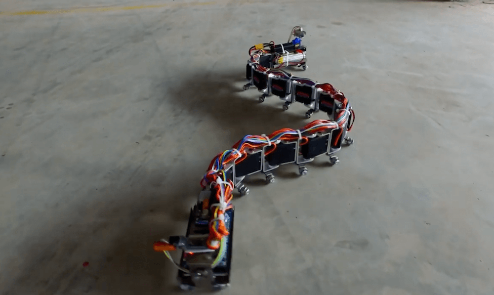
Robo-snake slithers across the ground under Arduino control
Reading Time: < 1 minuteRobo-snake slithers across the ground under Arduino control Arduino Team — September 13th, 2019 What has a dozen servos, a WiFi camera, and an Arduino Mega for a brain? Nevon Projects’ snake-bot, of course! This impressive robot uses a total of 12 servos for locomotion and can travel across a variety…
-

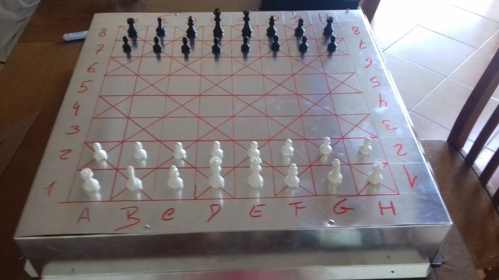
Play chess using voice commands and Arduino
Reading Time: 2 minutesPlay chess using voice commands and Arduino Arduino Team — September 3rd, 2019 Consider the game of chess. It’s a game that flexes one’s “mental muscles” rather than relying on brute strength, but if you don’t have the ability to actually move the pieces, things get a bit more challenging. If you’re…