Schlagwort: arduino

  • Recreating the Death Star Trench Run scene with LEGO

    Recreating the Death Star Trench Run scene with LEGO

    Reading Time: 2 minutes

    Recreating the Death Star Trench Run scene with LEGO

    Arduino TeamJanuary 9th, 2019

    South Korean LEGO Certified Professional Wani Kim, with the help of Olive Seon, has created an incredible replica of the Death Star Trench Run scene from Star Wars: Episode IV – A New Hope.

    The LEGO diorama—which measures 2,680mm (8.79 feet) long, 1,370 mm (4.49 feet) deep, and stands 1,100 mm (3.60 feet) tall— features defensive turrets, along with Luke’s X-Wing, the wreckage of another Rebel ship, and Vader and two TIE Fighters in pursuit.

    The build consists of 80,000 LEGO bricks and 100 minifigures, and even includes a cutaway of the back to reveal the insides of this astronomical object. If that wasn’t enough, an Arduino was used to coordinate flashing effects to further enhance this iconic recreation. 

    Additional images of Kim’s impressive project, plus some of his other work, can be found on Instagram.

    Website: LINK

  • Convert an ordinary longboard to electric with the help of Arduino

    Convert an ordinary longboard to electric with the help of Arduino

    Reading Time: 2 minutes

    Convert an ordinary longboard to electric with the help of Arduino

    Arduino TeamJanuary 9th, 2019

    After going through what not to do when building an electric longboard, Electronoobs is now ready to show us how to control one of these devices. For his project, the YouTuber used a 6S battery pack, an ESC, a brushless motor, and an Arduino Nano, along with a handheld RC transmitter and receiver.

    Underneath the deck, he’s broken up the hardware mounting into two parts—a front compartment contains the unit’s ample battery, while a rear enclosure houses the rest of the components.

    The Arduino Nano receives PWM signals directly from the receiver, then translates them to ESC inputs, allowing for better handling of how the board starts and stops.

    You can find more details on Electronoobs’ page here and in his video below! 

    [youtube https://www.youtube.com/watch?v=WV2VjxwtC2I?feature=oembed&w=500&h=281]

    Website: LINK

  • Destroyed books tell a unique story

    Destroyed books tell a unique story

    Reading Time: 2 minutes

    Destroyed books tell a unique story

    Arduino TeamJanuary 9th, 2019

    When you pick up a book, the text inside is normally the point, but what if the book itself was the story? That’s the idea behind Alistair Aichison’s Alt.Ctrl.GDC exhibition called “The Book Ritual.”

    Aichison’s work is told through an interactive computer installation, where an onscreen book talks about loss, but also encourages you to add your story by creatively modifying a real book.

    The process involves cutting and marking the book, and even requires the user to tear out pages to put it through an actual shredder—this is meant to evoke feelings of grief and regret, ultimately leading to the formation of new memories.  

    Control is accomplished using infrared sensors that verify page destruction, along with an Arduino that interfaces with the computer running this Unity-based game.

    The Book Ritual is a narrative game played using a real book and a real shredder. Your book becomes a character talking to you through the screen. It has a story to tell, but it wants you know your own story too. It asks you to write in its pages and deface it in creative ways to reflect your feelings. The book also needs you to tear out its pages and put them through a shredder.

    This is where the custom hardware comes in: the shredder is attached to the computer by a USB cable and detects when paper’s going through it. So, you actually need to shred pages in order to progress.

    The shredder itself is dressed up as a character, with big cartoon eyes and teeth. Because the subject matter is quite melancholic, I want the player to feel welcomed in by something innocent, childlike and friendly.

    More details on the project can be found in Gamasutra’s recent article and on Aichison’s website here.

    [youtube https://www.youtube.com/watch?v=MZ3qGdS_8Q8?feature=oembed&w=500&h=281]

    Website: LINK

  • Sam Battle’s Synth Bike 3.0 dissected after months on display

    Sam Battle’s Synth Bike 3.0 dissected after months on display

    Reading Time: 2 minutes

    Sam Battle’s Synth Bike 3.0 dissected after months on display

    Arduino TeamJanuary 8th, 2019

    Back in June 2017, Sam Battle (aka LOOK MUM NO COMPUTER) released the Synth Bike 3.0, a stationary bike with handlebars adorned with a functional synthesizer. This was promptly put on display at the Science Gallery Dublin, where it was ridden by approximately 130,000 people over six to eight months. 

    In his latest video, Battle decides to open up the control panel to revive it for an upcoming tour. The good news is that the system is still mostly functional, though a couple of the device’s Arduino—it’s run by a dozen Nanos along with four frequency central boards, a SparkFun WAV trigger, and a bunch of stripboard circuits—are missing. 

    After deciphering what he was thinking well over a year ago, considering what he might do differently today, reattaching wires, and tinkering, he’s able to get things functional. This is, of course, followed by the requisite solo synth-bike performance.

    More details on how Battle’s beat-banging bike can be found here. 

    [youtube https://www.youtube.com/watch?v=zw0vGARqgr4?feature=oembed&w=500&h=281]

    Website: LINK

  • FelixMatic automatically feeds your cat at preset times

    FelixMatic automatically feeds your cat at preset times

    Reading Time: 2 minutes

    FelixMatic automatically feeds your cat at preset times

    Arduino TeamJanuary 4th, 2019

    For busy people with unpredictable schedules, keeping one’s feline friend fed in a timely manner can be a challenge. Fortunately, there are automatic cat food dispensers available, or you can even build one yourself.

    Open Electronics’ 3D-printed device, called “FelixMatic,” claims to be more complex and complete than average off-the-shelf solutions. Not only can it be programmed to supply up to nine meals a day using a spiral-action rotary feeder, but it also measures food levels with a load cell for dispensing feedback. 

    Control is via an Arduino Uno along with an RTC shield for meal timing, while the user interface consists of an LCD display and five buttons.

    Having a pet involves big responsibilities, first of all granting them food; unfortunately, a hectic lifestyle and imposed work hours do not go hand-in-hand with the needs of our four-legged friends, and surely anyone living on their own will have a hard time providing the pets meals on schedule. In order to solve a problem that is surely dear to any pet owner, and especially cat and dog owners, we have designed a device we called FelixMatic: it is a practical automatic dispenser of dry food for cats (or small dogs) equipped with a high-capacity container that can easily be opened from the top and a bowl to collect the kibble when it is supplied. We know we can already find automatic dispensers on the market, however, our example is unique because it can be programmed with 9 meals a day in order to supply very precise quantities of dry food.

    The way the dispenser works is more complex and complete than the average available product on the market, in fact, it does not only supply food but it also gives exact doses as decided by us; basically, at a preset time, a cochlea at the base of the container will turn, and drop a certain amount of kibble in the bowl, regulated by a dedicated weight sensor.

    Website: LINK

  • Wind your thread automatically with this Arduino-powered machine

    Wind your thread automatically with this Arduino-powered machine

    Reading Time: 2 minutes

    Wind your thread automatically with this Arduino-powered machine

    Arduino TeamJanuary 3rd, 2019

    If you ever wondered how thread could be wound on spools without human intervention, this build by Mr. Innovative will show you one option. 

    The YouTuber’s DIY machine features a motor to rotate a small roller, pulling thread off a larger “feeder” spool. An encoder disk and photoelectric sensor are used to measure how much thread has been dispensed, and a servo-powered arm swings back and forth to allow the thread to feed evenly.

    The device is controlled by an Arduino Uno and custom PCB shield, while an encoder and OLED display serve as the user interface.

    I have made a thread coil winding machine, using Arduino and 3D-printed parts. For GUI I have used 0.96 OLED display, and for user input I have used a rotary encoder knob. A photoelectric speed sensor is used to measure the length of thread.

    The machine has two modes of operation. 1st is manual mode in which thread starts to wind on coil until stop is not pressed. In 2nd mode, auto mode, the machine will wind the thread as per the user predefined length.

    Parts, code, and print files can be found in the video description if you’d like to construct something similar.

    [youtube https://www.youtube.com/watch?v=tsxu_KMYnTs?feature=oembed&w=500&h=281]

    Website: LINK

  • Squeeze through pipes with this six-wheeled robot

    Squeeze through pipes with this six-wheeled robot

    Reading Time: 2 minutes

    Squeeze through pipes with this six-wheeled robot

    Arduino TeamJanuary 3rd, 2019

    If you need a robot to traverse piping systems, what are you to do? You could purchase a (very expensive) inspection robot, or you could instead build your own like the prototype pipe-crawler presented here. 

    The device features six spring-loaded wheel assemblies that help it get a grip on different diameters of pipe, with two of the wheels powered for locomotion.

    An Arduino Uno controls the uniquely-shaped bot, with an LN298N H-bridge used to regulate the three 9V batteries wired in series that run the motors. 

    Pipeline systems deteriorate progressively over time through various means. Pipeline inspection robot are designed to remove the human factor from labour intensive or dangerous work environments and also to act in inaccessible environment. However, if you take a look at the prices of those robots you will find that they are way too expensive.

    This project aims to create another kind of pipeline inspection robot. Because we think that It is beneficial to have a robot with an adaptable structure to the pipe diameter, and cheaper at the same time.

    Our challenge is to make this robot adaptable to diameters varying from 260mm to 390mm based on two sliding mechanisms.

    Be sure to see it in action in the short video below! 

    [youtube https://www.youtube.com/watch?v=EsJhEv6tLso?feature=oembed&w=500&h=281]

    Website: LINK

  • Control model trains wirelessly with your smartphone

    Control model trains wirelessly with your smartphone

    Reading Time: < 1 minute

    Control model trains wirelessly with your smartphone

    Arduino TeamJanuary 2nd, 2019

    Model trains have been a staple of DIY hobbiysts for generations, and while wireless control options can be purchased, KushagraK7’s hack lets you use your phone instead.

    The setup consists of an Arduino Uno, along with a motor driver shield to vary the trains’s peed and direction, as well as flip turnouts to allow for different sections of track to be used.

    The system employs a novel interface system, where an off-the-shelf Bluetooth receiver passes DTMF (telephone dial tones) to a decoder board, which then sends this decoded data on to the Arduino. While some might opt for an HC-05 Bluetooth module or similar, this enables control with a standard tone generator app, and the phone could even be physically connected via a stereo cable if convenient.

    [youtube https://www.youtube.com/watch?v=u5J_W7DCo_o?feature=oembed&w=500&h=281]

    Website: LINK

  • An e-skateboard controller made from scratch with Arduino

    An e-skateboard controller made from scratch with Arduino

    Reading Time: < 1 minute

    An e-skateboard controller made from scratch with Arduino

    Arduino TeamJanuary 2nd, 2019

    Last June, Timo Brinschein bought a Qu4tro electric skateboard with hopes of using it for fun and commuting duties. Unfortunately, while the skateboard itself worked well, the remote had many shortcomings.

    Since replacing the skateboard’s controls entirely was out of reach, he instead settled on the “small” job of reverse engineering and swapping out the wireless controller for one of his own designs. 

    The resulting build uses an Arduino Nano as the brains of the device, along with the well-known nRF24L0+ module for wireless communication. Everything is housed inside a custom 3D-printed enclosure. 

    Code for the project is available on GitHub, and print files for the excellent control handle is on Thingiverse.

    Website: LINK

  • Electronoobs creates his own Bluetooth-controlled Daft Punk helmet

    Electronoobs creates his own Bluetooth-controlled Daft Punk helmet

    Reading Time: < 1 minute

    Electronoobs creates his own Bluetooth-controlled Daft Punk helmet

    Arduino TeamJanuary 2nd, 2019

    If you like electronic music, you’ve certainly admired Daft Punk’s glowing electronic helmets. While the originals are amazing, as shown in this Electronoobs tutorial, you can now make a very good replica for around $20 and 30 hours of print time.

    Print files for the helmet itself are based on this Thomas Bangalter build by the Ruiz Brothers, and similar to that one, a good amount of sanding and finishing was needed to give it a metallic look. 

    Electronoobs’ helmet features seven WS2812 RGB LED strips, all connected to an Arduino Nano. Everything is controlled over Bluetooth by a custom Android app made with the MIT App Inventor, along with a microphone that allows the visor to react to music.

    [youtube https://www.youtube.com/watch?v=RHGvi-HTYIs?feature=oembed&w=500&h=281]

    Website: LINK

  • High school play gets a simulated sports scoreboard

    High school play gets a simulated sports scoreboard

    Reading Time: 2 minutes

    High school play gets a simulated sports scoreboard

    Arduino TeamJanuary 2nd, 2019

    Maker “DJ’s Fantasi” is the technical director at his local high school’s theater arts program, and when the director of their winter production of Disney’s High School Musical requested a scoreboard prop, he excitedly set to work. 

    The resulting build consists of four 7-segment displays, lit up by strips of non-programmable LEDs. 

    Numbers on the device are shown with the help of an Arduino Mega, which takes input via a single-channel remote. Seven I/O pins are used to indicate each segment to be displayed, and another four multiplex the signal into the required four digits.

    While a more general input device could be used, this particular scoreboard was especially set up for this musical, sequencing through numbers that correspond to the performance on command.

    More details on this impressive project can be found here.

    Website: LINK

  • Build a tachometer for your metal lathe with Arduino

    Build a tachometer for your metal lathe with Arduino

    Reading Time: < 1 minute

    Build a tachometer for your metal lathe with Arduino

    Arduino TeamJanuary 2nd, 2019

    If you manage to get a small lathe in your home shop, it will likely come with a dial to adjust the speed, but it may not have a tachometer to tell you if it’s actually spinning at your desired setting. Rather than accept this imprecision on his model, hacker Tony Scarpelli designed his own non-contact tachometer using an Arduino Nano.

    The build is ingeniously simple, and mounts an infrared proximity sensor near gearing in the back of the lathe’s headstock. White paper is placed on this rotating surface, allowing the sensor to tell between this marker and the otherwise dark surface as it spins. Sensor pulses are recorded by the Arduino, which outputs RPM values on a small 16×2 LCD display.

    Website: LINK

  • Star Trek tricorder-style heart rate monitor

    Star Trek tricorder-style heart rate monitor

    Reading Time: < 1 minute

    Star Trek tricorder-style heart rate monitor

    Arduino TeamDecember 28th, 2018

    A heart rate monitor can be an important tool for tracking fitness and exertion levels, but what if you want something a bit more interesting style-wise? For a novel idea, be sure to check out the project shown below from “Taste The Code.”

    In it, Blagojce Kolicoski turns a handle used for launching rotating toys into something reminiscent of a tricorder from Star Trek.

    The build stuffs an Arduino, a pulse sensor, and a tiny OLED display into the handle, which conveniently already had accommodations for three AA batteries. This, along with the monitor’s I2C connection, meant that wiring everything up was quite simple. 

    Want to make your own? Instructions are available here, while code can be found on GitHub.

    [youtube https://www.youtube.com/watch?v=iVN3gXZ72P8?feature=oembed&w=500&h=281]

    Website: LINK

  • Create mesmerizing designs in the sand with this Arduino-controlled Zen table!

    Create mesmerizing designs in the sand with this Arduino-controlled Zen table!

    Reading Time: < 1 minute

    Create mesmerizing designs in the sand with this Arduino-controlled Zen table!

    Arduino TeamDecember 27th, 2018

    A sandbox game generally refers to an open world computer simulation, but Tim Callinan’s fall semester project takes things in a different direction—an actual sandbox controlled by an Arduino and gShield.

    Callinan’s Zen table is capable of producing complicated designs in the sand, using a single steel marble that appears to magically move across the surface by itself.

    Underneath the sand assembly is a stepper-controlled gantry that acts like a laser cutter or other CNC tool, dragging the marble around with a powerful magnet. The results are stars, rotating squares, and other kaleidoscopic patterns, beautifully edge-lit with a series of RGB LEDs.

    Several other classmates were involved in making this build a reality, including Mark Morello, who wired and programmed the device.

    [youtube https://www.youtube.com/watch?v=D8uCUroAHD4?feature=oembed&w=500&h=281]

    Website: LINK

  • Draw on an oscilloscope with Arduino

    Draw on an oscilloscope with Arduino

    Reading Time: 2 minutes

    Draw on an oscilloscope with Arduino

    Arduino TeamDecember 27th, 2018

    If you’ve ever wanted to plot shapes using an oscilloscope, YouTuber Electronoobs reveals the tricks in his latest video. In it, he draws a Christmas tree, along with a few other shapes, and while that holiday is now past, there’s always the 2019. Of course, you don’t have to wait, as these concepts can be applied to anything you like throughout the year!

    In the video, Electronoobs uses an Arduino Nano to produce PWM signals on two channels, filtering each of them with a capacitor and resistor. As he explains, shapes must be fairly simple, and end in the same place they started. Even with these restrictions, once the oscilloscope it turned to x/y plot mode and the signal is tuned in, the results are quite good.

    In this tutorial we will use two pins from the Arduino to create fast PWM signals. With a small filter, we change the amplitude of that signal according to the width of the PWM pulse. By that, we can draw shapes on the oscilloscope when in XY mode.

    Code for the project can be found in Electronoobs’ write-up here.

    [youtube https://www.youtube.com/watch?v=nlCADL5_g-I?feature=oembed&w=500&h=281]

    Website: LINK

  • OpenLH robot automates biological exploration

    OpenLH robot automates biological exploration

    Reading Time: 2 minutes

    OpenLH robot automates biological exploration

    Arduino TeamDecember 20th, 2018

    If you’d like an easy way to accomplish repetitive biological experiments, the OpenLH presents a great option for automating these tasks. 

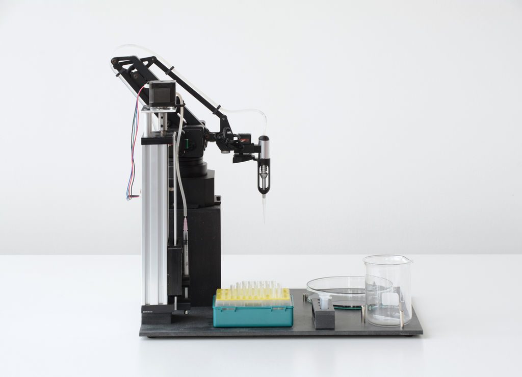
    The heart of the system is the Arduino Mega-controlled uArm Swift Pro robot, which is equipped with a custom end effector and syringe pump. This enables it to dispense liquids with an average error of just .15 microliters.

    A Python/Blockly interface allows the OpenLH to be set up for creative exploration, and because of the arm’s versatility, it could later be modified for 3D printing, laser cutting, or any number of other robotic duties. 

    Liquid handling robots are robots that can move liquids with high accuracy allowing to conduct high throughput experiments such as large scale screenings, bioprinting and execution of different protocols in molecular microbiology without a human hand, most liquid handling platforms are limited to standard protocols.

    The OpenLH is based on an open source robotic arm (uArm Swift Pro) and allows creative exploration. With the decrease in cost of accurate robotic arms we wanted to create a liquid handling robot that will be easy to assemble, made by available components, will be as accurate as gold standard and will cost less than $1,000. In addition the OpenLH is extendable, meaning more features can be added such as a camera for image analysis and real time decision making or setting the arm on a linear actuator for a wider range. In order to control the arm we made a simple Blockly interface and a picture to print interface block for bioprinting images.

    We wanted to build a tool that would be used by students, bioartists, biohackers and community biology labs around the world.

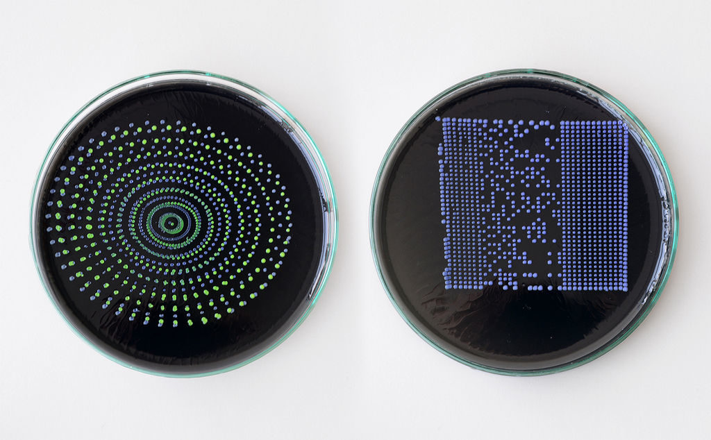
    The OpenLH can be seen in the video below, bioprinting with pigment-expressing E. coli bacteria.

    [youtube https://www.youtube.com/watch?v=r-m2pXBq76A?feature=oembed&w=500&h=281]

    Website: LINK

  • An inexpensive device for analyzing roasted coffee beans

    An inexpensive device for analyzing roasted coffee beans

    Reading Time: 2 minutes

    An inexpensive device for analyzing roasted coffee beans

    Arduino TeamDecember 18th, 2018

    While you may not consider in detail how your coffee is roasted, those that produce it must pay special attention to make sure that the end product is consistent. Equipment to help analyze roasted coffee is normally quite expensive, but using a near-infrared sensor, Arduino Uno and Bluetooth module, Spencer Corry was able to make his own analysis setup.

    As shown in the video below, after calibration, beans are inserted into the analysis chamber using a tryer scoop. Light is shined onto the roasted beans, and the intensity of the reflected near-infrared radiation is analyzed in six different wavelengths. Intensity data is then transmitted via Bluetooth to a smart device, which can be used to make sure things are roasted perfectly.

    There has recently been a growth of small roasting companies offering custom in-house roasts. These companies are looking for less expensive alternatives to hiring and training a roast master or using the expensive Agtron Process Analyzer. The Degree of Roast Infrared Analyzer for Coffee Roasters, as described in this document, is meant to be an inexpensive means of measuring the degree of roast of coffee beans. The Degree of Roast Infrared Analyzer uses a tryer, a tool found on coffee roasters used to sample the coffee during roasting, to hold a sample of coffee. The tryer is inserted into the analyzer where the AS7263 NIR Spectral sensor is used to measure 6 different infrared bands (610, 680, 730, 760, 810, and 860nm). The reflectance measurements are transmitted via Bluetooth and can then be correlated to the degree of roast. The analyzer must first be calibrated by pressing a button on the inside of the box in which the PVC is used as a white balance as it has a relatively flat reflectance in the spectral range detected by the sensor.

    [youtube https://www.youtube.com/watch?v=NgYNQm1fcKk?feature=oembed&w=500&h=281]

    Website: LINK

  • A multi-matrix scrolling text display for absolute beginners

    A multi-matrix scrolling text display for absolute beginners

    Reading Time: < 1 minute

    A multi-matrix scrolling text display for absolute beginners

    Arduino TeamDecember 18th, 2018

    For this build, YouTuber DIY Perspective goes through the process of constructing a scrolling text display with two 8×8 matrices. 

    His instructions, along with an excellent video, go through the process from the very basics, including things that many would take for granted, like installing the Arduino IDE. For this reason, it could be a great introduction for those that are new to the maker electronics scene.

    The device is controlled via an Arduino Nano and can be powered by an 18650 battery or wall charger. While relatively simple electronics-wise, what really sets this project apart is the beautifully finished wooden enclosure. It’s held together with glue, and nicely sealed with a single screw!

    [youtube https://www.youtube.com/watch?v=lIQ_YTP7uC8?feature=oembed&w=500&h=281]

    Website: LINK

  • An Arduino-based rocket motor thrust test stand

    An Arduino-based rocket motor thrust test stand

    Reading Time: 2 minutes

    An Arduino-based rocket motor thrust test stand

    Arduino TeamDecember 17th, 2018

    If you enjoy model rocketry, you may wonder just what the thrust curve of the motors you’re using looks like. In order to answer that question, YouTuber ElementalMaker decided to construct his own test stand using an Arduino Uno coupled to a 10Kg load cell with an HX711 amplifier board. The test procedure is started with a little red button, and after warning LED blinks away for 10 seconds, it activates a relay and fires the motor under into the stand.

    The experimental setup seen in the video yields successful thrust curves for both a ½ inch and ¾ inch motor. As you might expect, the ¾ produces more thrust than its smaller cousin, though at 2,683 grams versus the ½ inch motor’s 658, it’s an impressive difference indeed. 

    The heart of the stand is a common load cell (the sort of thing you’d find in a digital scale) coupled with a HX711 amplifier board mounted between two plates, with a small section of vertical PVC pipe attached to the topmost plate to serve as a motor mount. This configuration is capable of measuring up to 10 kilograms with an 80Hz sample rate, which is critically important at this type of rocket motors only burn for a few seconds to begin with. The sensor produces hundreds of data points during the short duration of the build, which is perfect for graphing the motor’s thrust curve over time.

    Given such a small window in which to make measurements, [ElementalMaker] didn’t want to leave anything to chance. So rather than manually igniting the motor and triggering the data collection, the stand’s onboard Arduino does both automatically. Pressing the red button on the stand starts a countdown procedure complete with flashing LED, after which a relay is used to energize a nichrome wire “electronic match” stuck inside the motor.

    The project is based on a paper archived here if you’d like to examine the design.

    [youtube https://www.youtube.com/watch?v=-yq1EmTkBCs?feature=oembed&w=500&h=281]

    Website: LINK

  • Build a single-pixel scanning camera with an RGB sensor

    Build a single-pixel scanning camera with an RGB sensor

    Reading Time: 2 minutes

    Build a single-pixel scanning camera with an RGB sensor

    Arduino TeamDecember 15th, 2018

    Sensors like the TCS34725 from Adafruit can detect a single color. It stands to reason then, that if you were to aim this sensor at a multitude of points and record the resulting data, you could have a one-pixel camera. As seen here, Tucker Shannon decided to take this concept and run with it, constructing his own with an Arduino Uno and a pair of stepper motors.

    The device looks like something akin to some sort of auto-turret, and directs the sensor in a square spiral for image acquisition. The resulting pictures are certainly low-res, but good enough to pick out recognizable forms with a little imagination. 

    The color sensor tells the Arduino what color it “sees” at any given time. By pointing it at every single point within a field of view, I can record these colors and use them later to reconstruct an image.

    Using two stepper motors, the camera points the sensor at every “pixel” within the photo and records what it sees. It uses these values to “paint” a picture of whats in front of it!

    Components include: 1x Arduino Uno, 1x Adafruit RGB Color Sensor TCS34725, x2 BYJ-48 Stepper motor with drivers, x1 3mm OD aluminum tube, x20 M3x6mm fasteners. Alternatively a photoresistor can be used in place of the RGB sensor for black and white photos!

    Code for the project can be found on GitHub, and print files are on Thingiverse if you’d like to build your own!

    Website: LINK

  • Drone morphs into the perfect shape in mid-air

    Drone morphs into the perfect shape in mid-air

    Reading Time: < 1 minute

    Drone morphs into the perfect shape in mid-air

    Arduino TeamDecember 14th, 2018

    Drones come in many shapes and sizes, but for the most part their motor pods are fixed during flight. Inspired by the way birds can fold their wings, researchers from the University of Zurich and EPFL have come up with a quadcopter capable of changing motor orientation dynamically in mid-air. This allows the nominally X-shaped drone to fold itself into tight spaces, and even configure itself for optimal handling.

    Flight control is handled by an advanced Snapdragon quad-core computer, while the servos that actuate the motor arms are controlled using an Arduino Nano. 

    An interview about the project is available on IEEE Spectrum, while the Foldable Drone’s research paper, along with several more videos, can be found here.

    [youtube https://www.youtube.com/watch?v=jmKXCdEbF_E?feature=oembed&w=500&h=281]

    Website: LINK

  • Keep track your weekly tasks with Arduino and arcade buttons

    Keep track your weekly tasks with Arduino and arcade buttons

    Reading Time: 2 minutes

    Keep track your weekly tasks with Arduino and arcade buttons

    Arduino TeamDecember 14th, 2018

    All of us have daily tasks we need to perform, but what if you often forget whether you’ve done something, or simply need to give your child a little extra motivation? One great way would be Simon Prickett’s Arduino Task Tracker, inspired by Simone Giertz’s Every Day Calendar. 

    Prickett’s clean-looking device is built into an electrical junction box, which holds the guts, including an Arduino Uno inside. It also exposes eight arcade-style LED buttons on top.

    After you, or in this case Prickett’s son, complete a chore, press one of the seven green buttons. Once they are all lit, the Arduino Task Tracker produces a “victory roll” sequence. The eighth red button is then used to start the week over again. 

    Sound like something you’d like to recreate? Code and more info for the project can be found GitHub.

    [youtube https://www.youtube.com/watch?v=BcS5LLRLeBo?feature=oembed&w=500&h=281]

    Website: LINK