— December 3rd, 2021
Breadboards are the first tool you break out in any prototyping journey and almost every project will utilize a breadboard at some point. Those breadboards often turn into a rats’ nest of overlapping wires that are difficult to trace, which makes it difficult to create an accurate schematic when it is time to design your PCB. To make your life easier, Nick Bild came up with a script that analyzes your physical breadboard to automatically generate a KiCAD schematic.
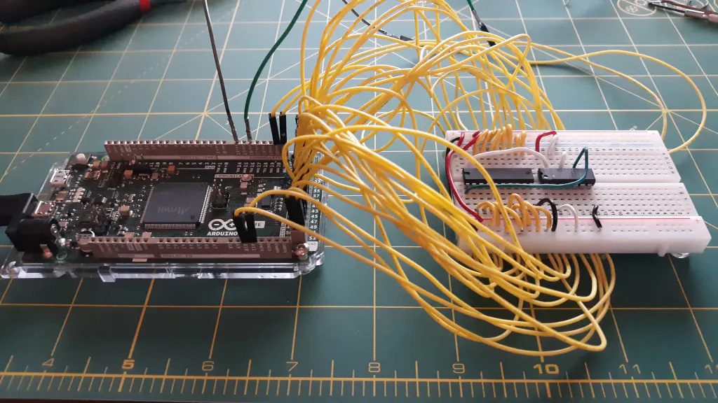
A breadboard is, at its core, a series of connectors. This script’s purpose is to identify every connection and associate it with the corresponding pin on a component. It is able to do that using a special breadboard that has every row of pins connected to an Arduino Due board I/O pin. A Python script running on a connected PC then checks every row for continuity. The user then inputs the component located at connection, and the script will draw a KiCAD schematic with wires between every component’s pins.
This script does have some serious limitations. The most obvious is that many ICs either don’t have internal continuity for every pin or only have internal continuity in certain states. To overcome that, the user must insert jumpers in place of some components. The user must also enter the component associated with each connection, because the script has no way of identifying components — it only checks for continuity. But even with those limitations, Schematic-o-matic can save you a lot of time and effort when you create schematics for particularly complex breadboard circuits.
Website: LINK